6. 3D Scanning and printing
Group Assignment: Characterizing the machine
Zortrax M-200
For this week’s group assignment we had to characterize the specifications of our LDM 3D Printer - Zortrax M-200. The software that we used to generate Z-Code (closed gCode for Zortrax printers) was Z-Suite, online at Zortrax Site and send to the machine through by SD card.
Check the design rules
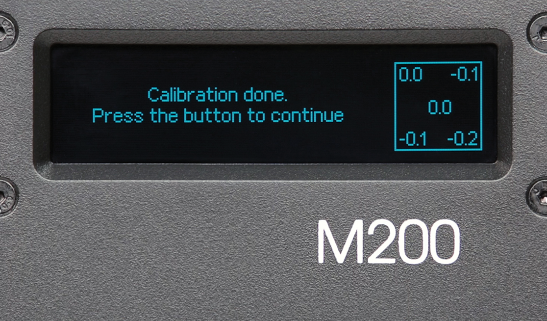
After guided Calibration process we have download some test files to characterize our 3D printer.
XYZ 20mm Calibration Cube –> thing:1278865
Overhang Tester, 5 - 90 degrees –> thing:261317
TEST_1
Setup
- Tool: 3D Printer - LDM
- Model: Zortrax M-200 (200.0 (X) x 200.0 (Y) x 185.0 (Z Max) mm Working Area)
- Nozzle: 1/64 (0.4mm)
- Materials: Z-ABS (ABS)
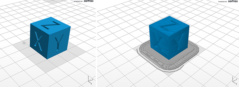
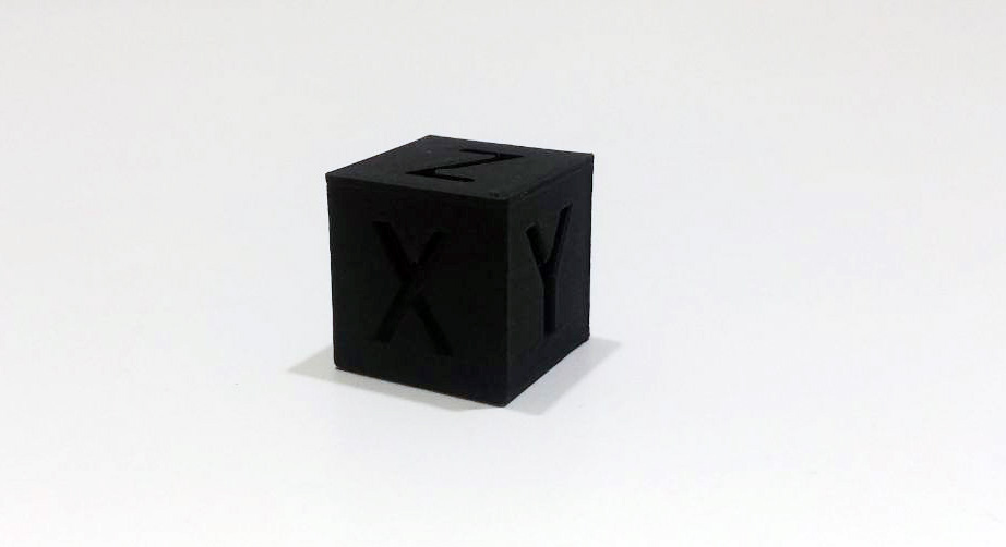
We did a “XYZ 20mm Calibration Cube” test using the downloaded file and prepare the Z-Code with this parameters:
Parameters
-
Application version: 2.7.1.0
- Estimated print time: 0h 39m
- Material: Z-ABS
- Material usage: 2.71m (6g)
- Printer: Zortrax M200
-
Profile: custom
- Support type: Editable
//no support needed for this model. I've no proceeded to generate them, but the follow parameters are default. - Support: 25°
- Gap XY: 0.28
- Spacing: 3.50
- Nozzle diameter: 0.4 mm
- Layer: 0.19 mm
- Quality: High
- Infill: 50%
- Fan speed: Auto
- Seam: Normal
- Outer contours: 0.00
- Holes: 0.00
- Surface layers Top: 7
- Surface layers Bottom: 5
- Support Lite: No
- Smart bridges: No
- Support type: Editable
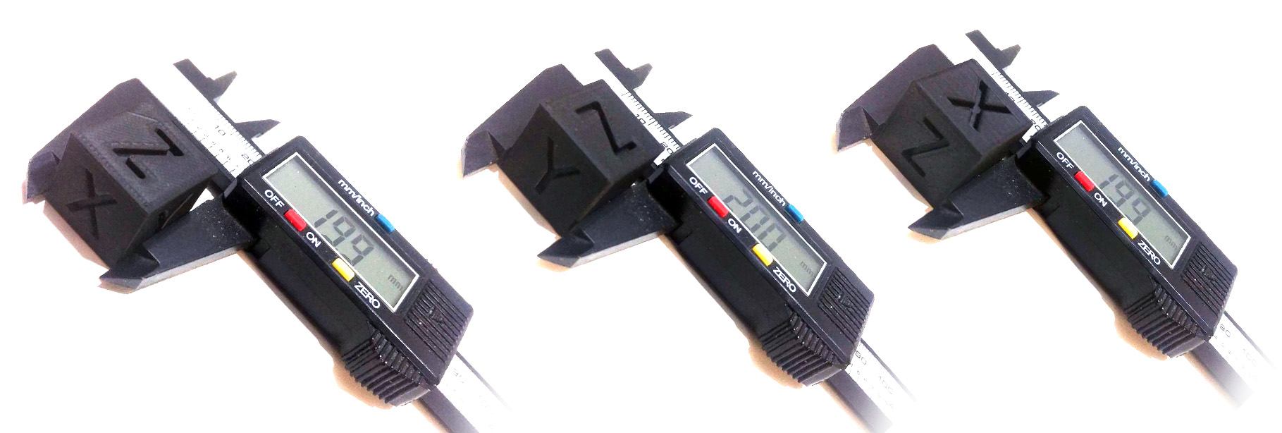
After waiting 39min… the original dimensions in the file are 20x20x20mm and after printed it we had removed the raft from the piece and measured every dimension with a caliper.
TEST_2
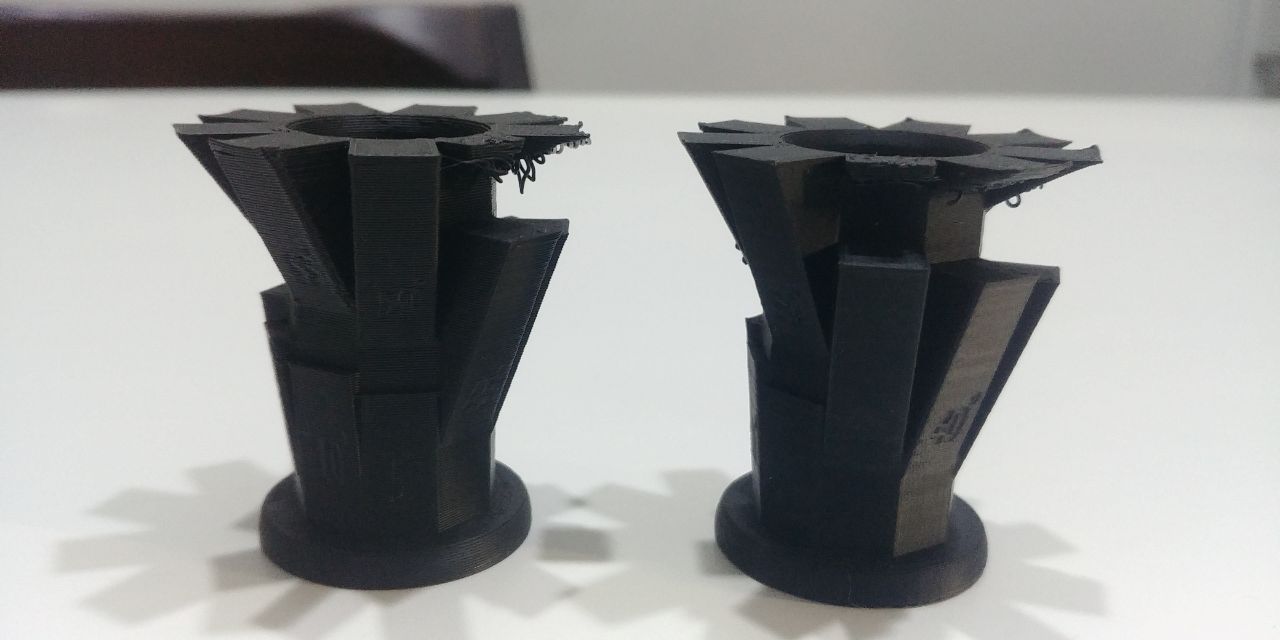
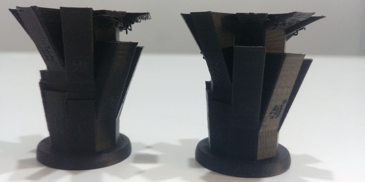
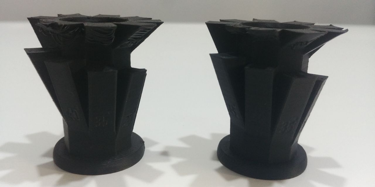
We did a “Overhangs not supported” test using the downloaded file and prepare two different Z-Codes to demonstrate how the layer height can influence the not supported pice with different angles.
Parameters_1
- Application version: 2.7.1.0
- Estimated print time: 1h 33m
- Material usage: 6.06m (14g)
- Printer: Zortrax M200
- Profile: Last settings
- Support type: Editable
//no support needed for this model. I've no proceeded to generate them, but the follow parameters are default. - Support: 25°
- Gap XY: 0.28
- Spacing: 3.50
- Material: Z-ABS
- Nozzle diameter: 0.4 mm
- Layer: 0.29 mm
- Quality: High
- Infill: 50%
Parameters_2
- Application version: 2.7.1.0
- Estimated print time: 1h 33m
- Material usage: 6.06m (14g)
- Printer: Zortrax M200
- Profile: Last settings
- Support type: Editable
//no support needed for this model. I've no proceeded to generate them, but the follow parameters are default. - Support: 25°
- Gap XY: 0.28
- Spacing: 3.50
- Material: Z-ABS
- Nozzle diameter: 0.4 mm
- Layer: 0.14 mm
- Quality: High
- Infill: 50%
In the following image you can see what we had described above.
We had made another test designing a simple 10mm cylinder and a base with four holes: the first hole with same diameter of the cylinder; the second with 0.05mm offset (diam. 10.1mm); the third with 0.1mm offset (diam. 10.2mm); the fourth hole with 0.15mm offset (diam. 10.3mm) is resulted the best choice for assembly cylinder and hole without game between.
Design for 3D printing
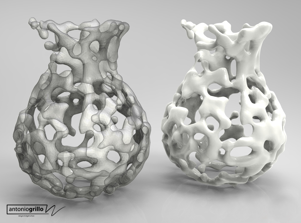
EVA - Evolutive Vase Algorithm is the name of this Design work and surely you can’t make it through SRP.
Why you can’t make it through Subractive method?
Both considering a milling with 3 axes and with 4 axes, there will always be points where, since there are overhangs, the cutter would not be able to remove the internal material.
Vase is generated by Grasshopper definition I made, based on David Stasiuk’s Marching Cubes definition.
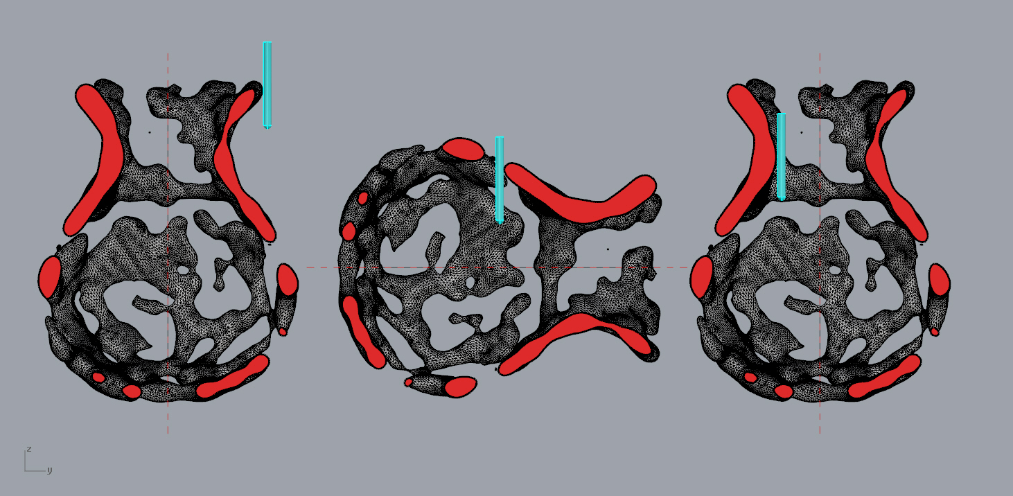
I started from design a revolve axes and a freeform curve as section to revolve.
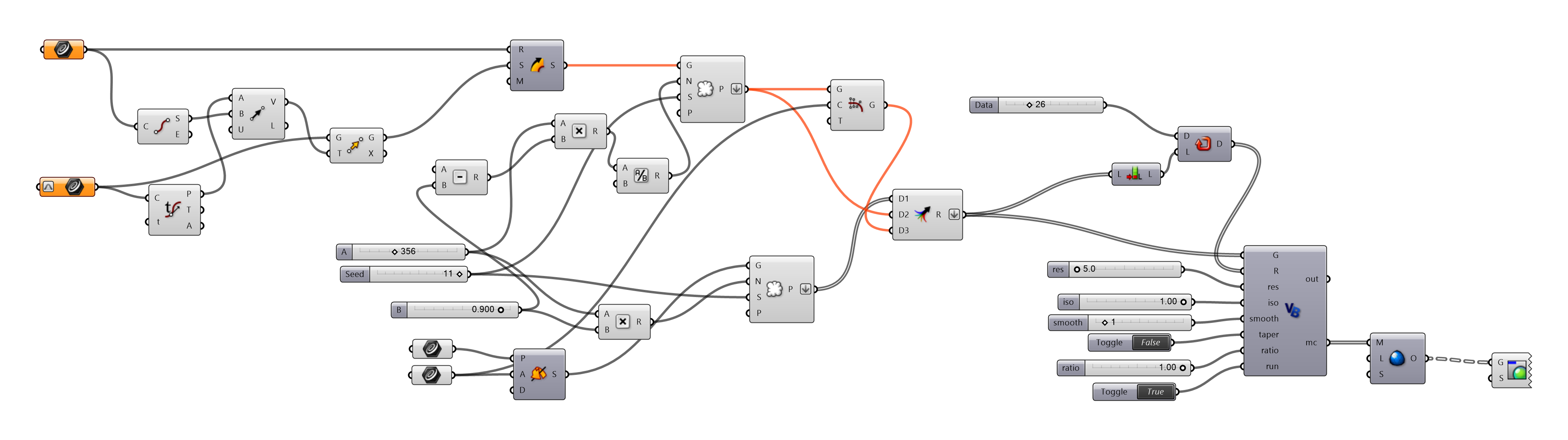
 The generation of 3D mesh is granted by GH definition like this …
and the following is one of many generated child of my DNA Vase Definition …
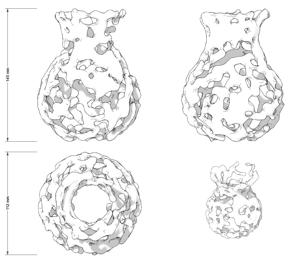
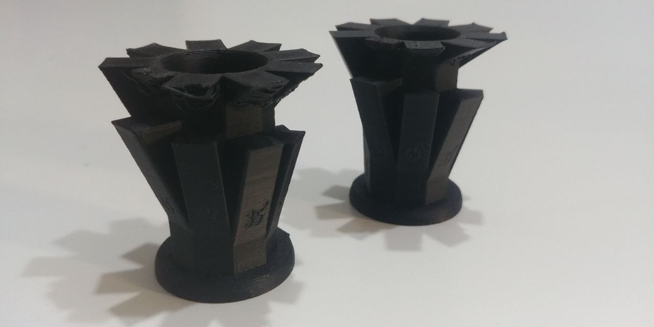
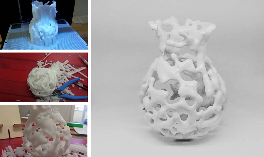
Once the .stl file was baked from Grasshopper and exported from Rhino, I generated the Z-Code and 3D printed it in Z-ABS material. The most challenging part was removing the supports.
Printing parameters
- Application version: 2.7.1.0
- Estimated print time: 20h 28m
- Material usage: 38m (81g)
- Printer: Zortrax M200
- Profile: Last settings
- Support: 25°
- Gap XY: 0.28
- Spacing: 3.50
- Material: Z-ABS
- Nozzle diameter: 0.4 mm
- Layer: 0.19 mm
- Quality: High
- Infill: 30%
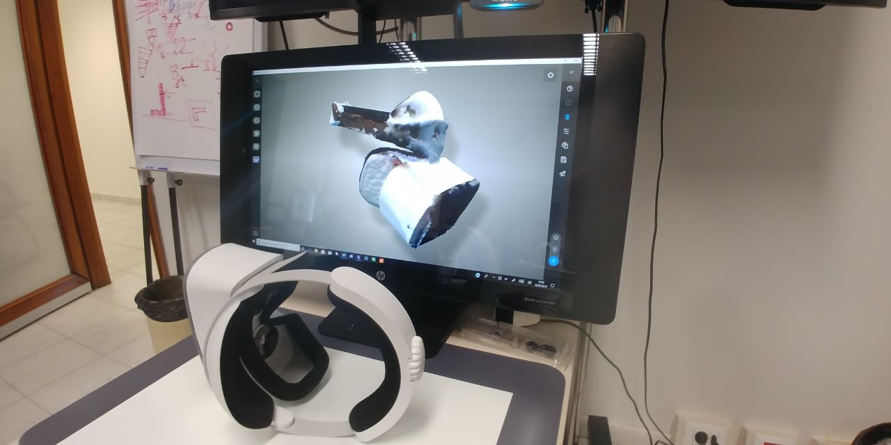
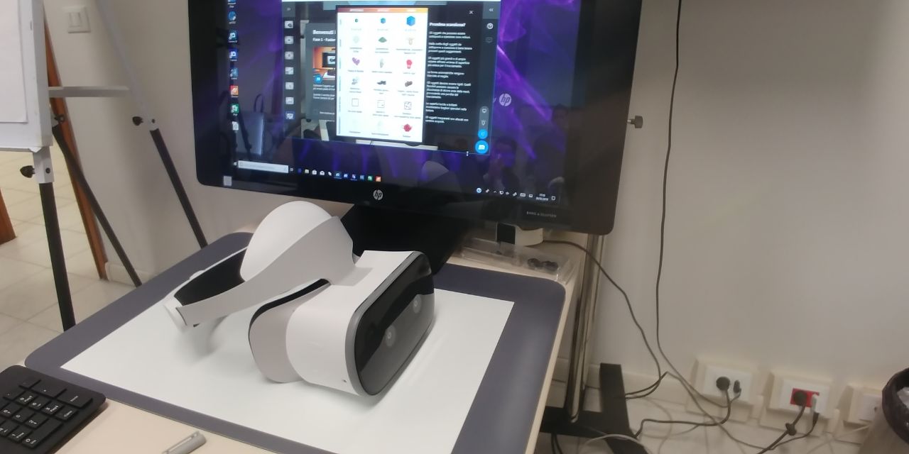
Scanning - The Sprout Pro G2
The 2016 model came with custom software to make 3D scans using structured light technology. For this, it combined the digital projector and the high resolution camera that are also integrated in the overhead unit.
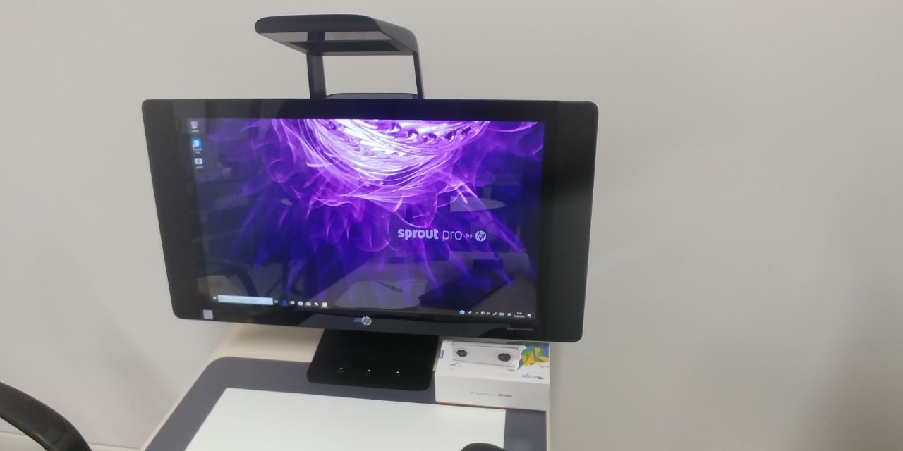
HP has integrated an Orbbec Astra S sensor (which is also available as a standalone device). So this time around, you can actually use the depth sensor for 3D scanning and HP has included a new application called Camera 3D for this.
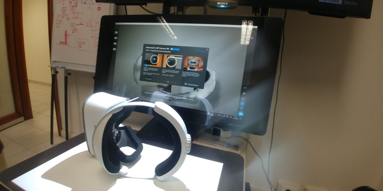
The Structured Light Scanning software 2016 Sprout Pro was clearly designed to make 3D scanning easy for everyone. Everything was operated through a step-by-step wizzard and the whole interface was touch-optimized.
It even projected instructions onto the Touch Mat that made it fool proof to place the 3D Capture Stage correctly and perform an initial background scan to enable the software to remove it from the actual scan later.