5. Electronics production
Group Assignment: Characterizing the machine
Roland SRM-20
For this week’s group assignment we had to characterize the specifications of our PCB production process on our Roland SRM-20. The software that we used for milling was Fab Modules, online at FabModules and send RML-1 files trough Roland VPanel sender.
HARDWARE
Setup
- Tool: Milling machine
- Model: Roland SRM-20 (203.2 (X) x 152.4 (Y) x 60.5 (Z) mm Working Area)
- Endmill: 1/64 (0.4mm) - 1/32 (0.79mm)
- Materials: FR1 board; 20mm MDF (sacrificial plane)
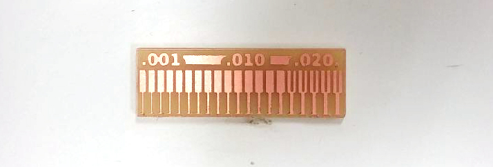
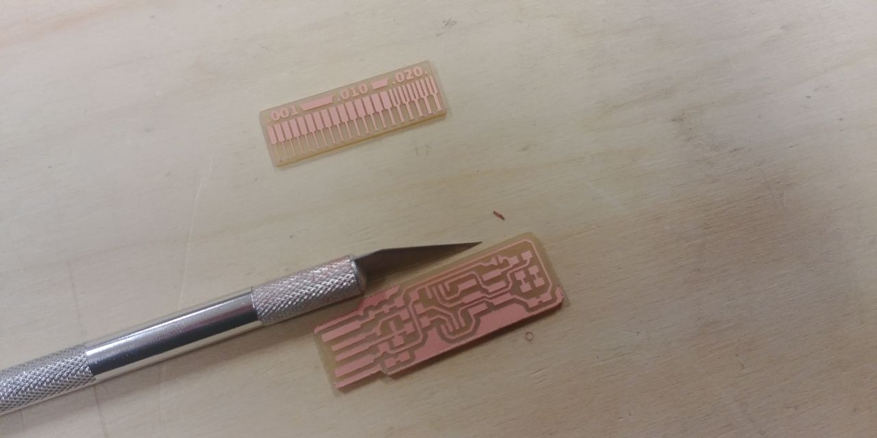
We did a linetest using these two files:
- linetest.png to milling the traces with 1/64 bit;
- linetest.interior.png to cut the outline with 1/32 bit.
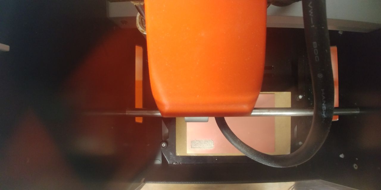
Before attempting to mill we had set the machine as follows:
- prepare a sacrificial plane;
-
using the double-sided adhesive tape, attach the 20mm MDF plane to the table; then attack the FR1 base on the sacrificial plane;
Advice
put the double-sided tape very flat on the surfaces.
-
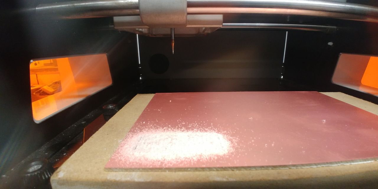
attach the milling bit in the collet and make sure it is 2 or 3 mm from the surface of the FR1;
-
zeroing the Z height, dropping the tip on the plane, making sure that the Z can theoretically get off at least the right amount to be able to mill.
Advice
In case you have not left enough space to get down to milling, the spindle will rise upwards moving as if it were milling.
-
zeroing the X and Y axes starting from the left-bottom side of the FR1 board.
SOFTWARE
The SRM-20 has a good mechanical resolution and the software resolution depend by the type of gcode that the sender manage:
Software Resolution:
| RML-1 | NC code | RML-1 | NC code | ||
|---|---|---|---|---|---|
| inches/step | 0.000039 | 0.000039 | mm/step | 0.01 | 0.001 |
As the smallest track to be milled was 1 mills, we chose to generate an RML-1 code with a resolution of 0.01mm, then we had used FabModules to generate the RML-1 codes:
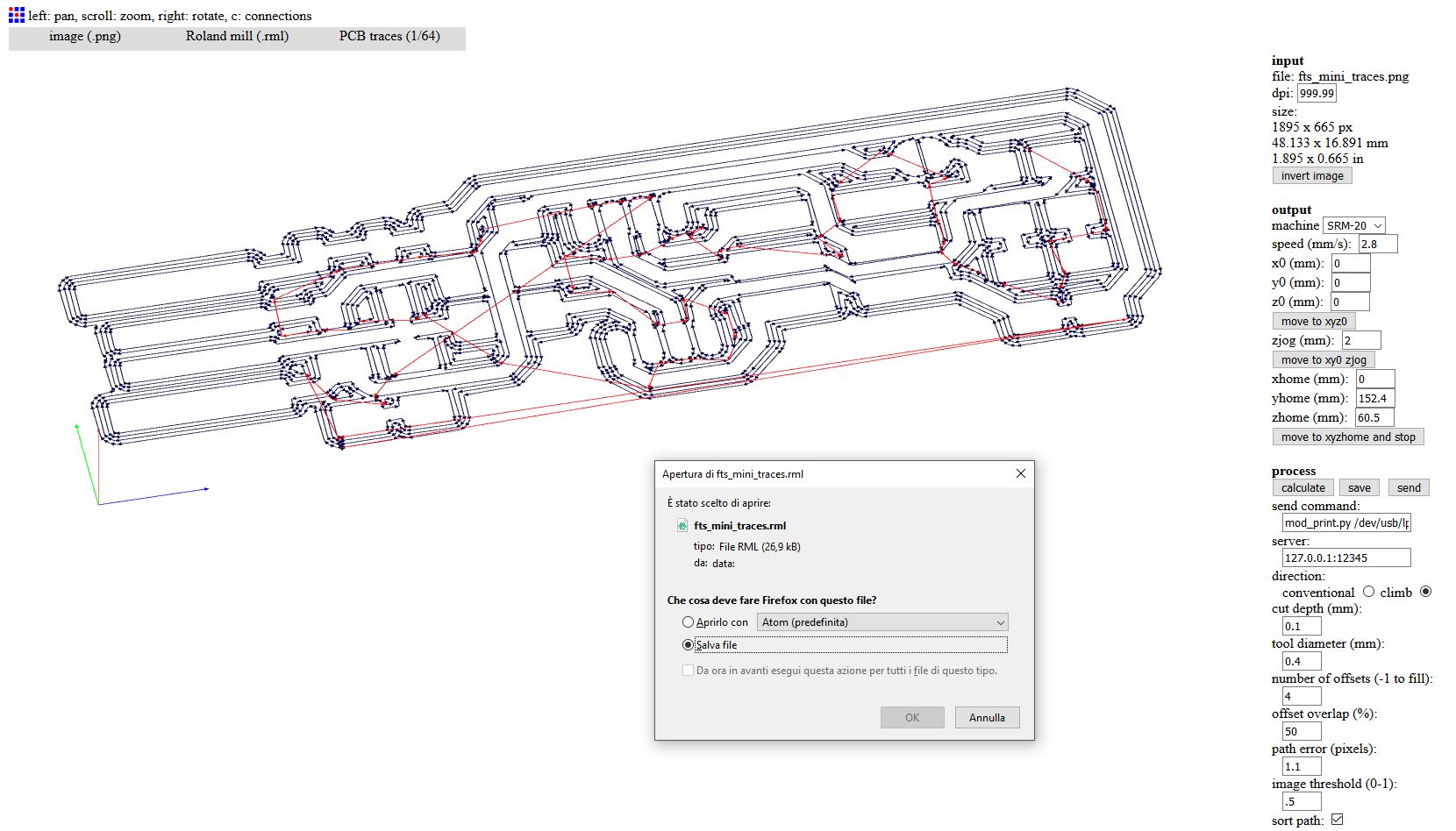
for Traces —>
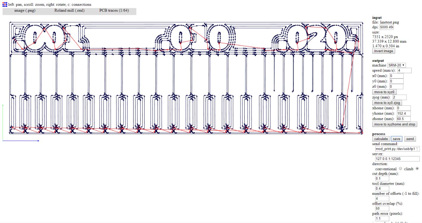
and send it to the milling machine trough by VPanel for SRM-20, we looked for the right setting of zero Z, Spindle (8000 rpm) and Cutting Speed (168 mm/min obtained from 70% of FabModules presetting - 4 mm/s).

The right one is the 2nd to the bottom.
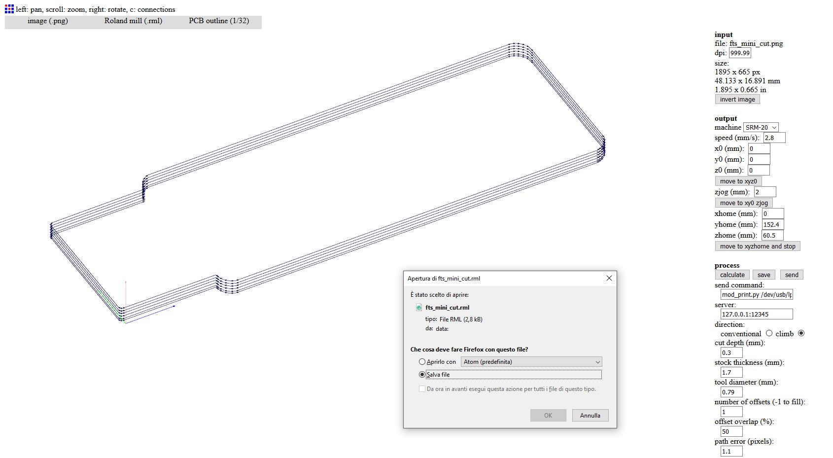
for Outline —>
At that time we were ready to cut the outline, but generating the RML code we have found an error, and we had thought that Neil played us a joke, why??
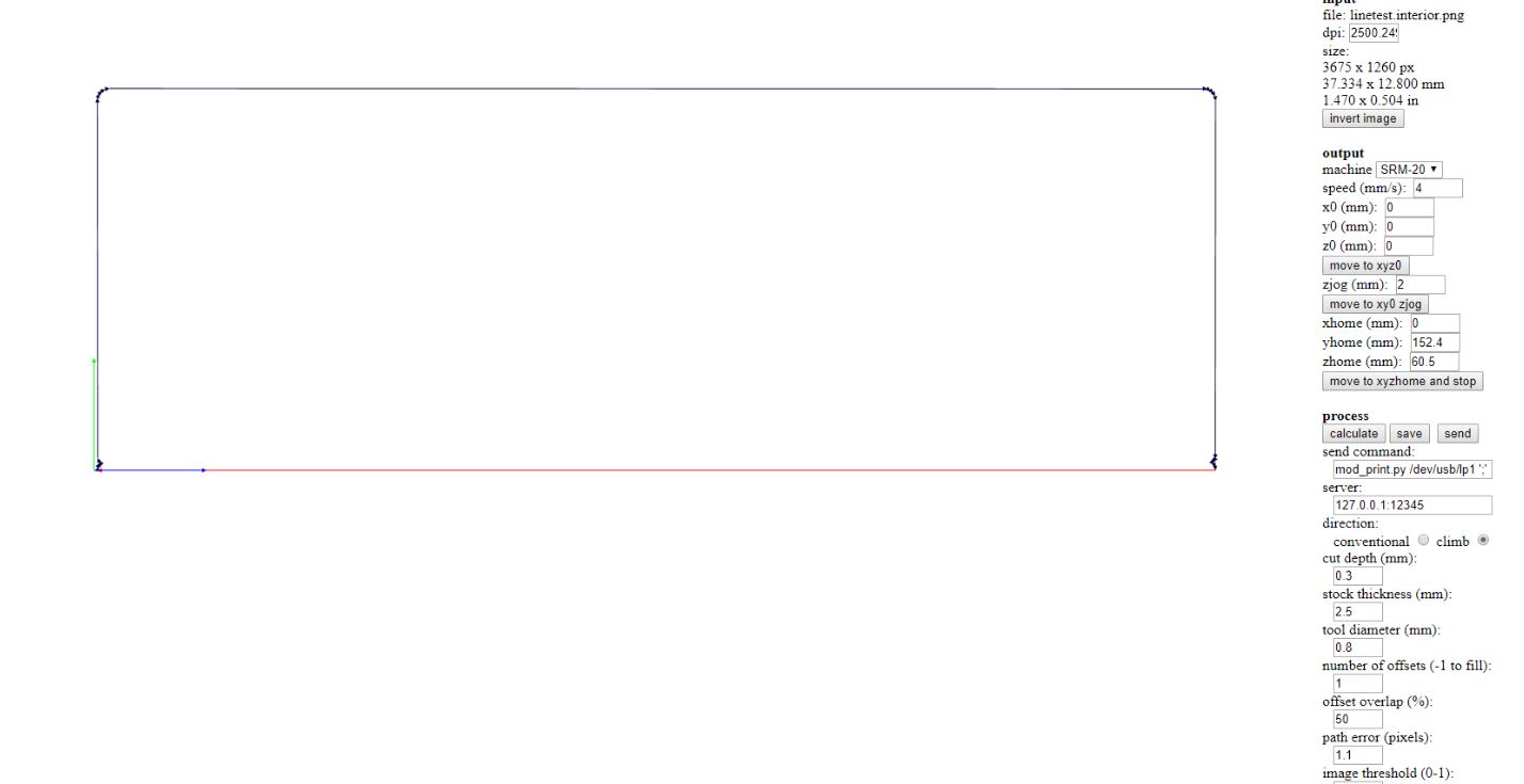
The red line on the bottom represent a Travel, without milling, and this happen because the .png image has a bottom row of transparent pixels.
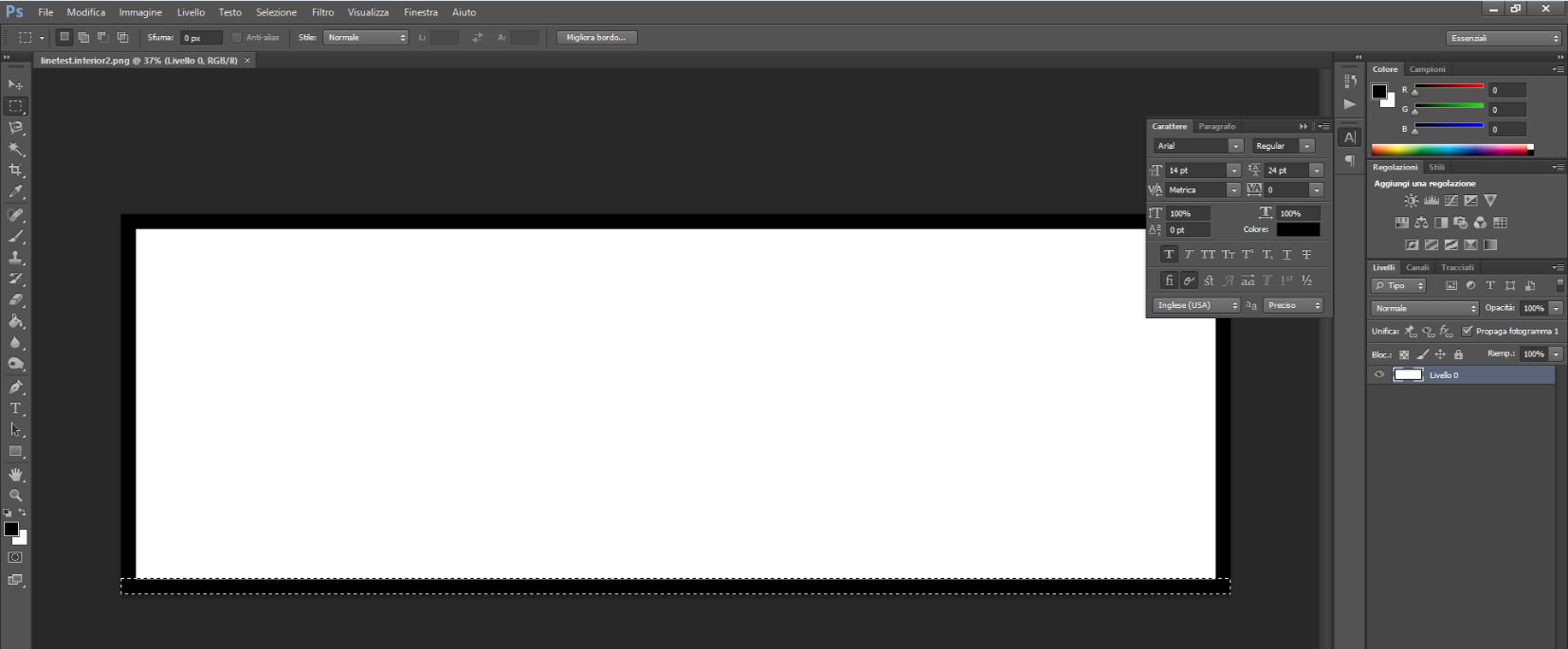
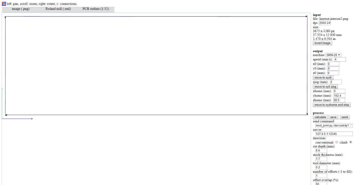
We had repaired the linetest.interior.png with Adobe Photoshop and we had generated a new one called linetest.interior2.png. At this point we had rebuilded the RML code and attached the 1/32 endmill to cut the board.
in-circuit programmer
FabISP - Brian version
1. Milling
Once the hardware has been prepared as described above in Hardware section of the group assignment, I’ve generated RML-1 code CAM trough Fabmodules again, starting from Brian’s PNG
I’ve used 168 mm/min (2.8 mm/s) Cut Speed and decreased Spindle Speed trought by VPanel around 8500 rpm
Than I’ve take the Zero point for X/Y and Z axes and launch the CUT adding the .rml files to the jobs, 1 by 1.
2. Assembling
Prepare the following Components to assembly on the PCB:
Components
- 1x ATtiny45
- 2x 1kΩ resistors
- 2x 499Ω resistors
- 2x 49Ω resistors
- 2x 3.3v zener diodes
- 2x LEDs
- 1x 100nF capacitor
- 1x 2x3 pin header

Note
The components that must be installed in the correct orientation:
- 3.3v zener diodes
- LEDs
- ATtiny45
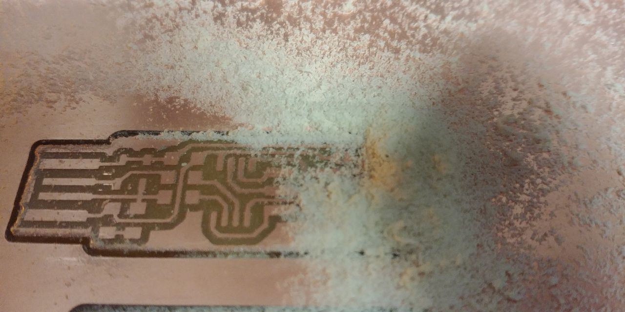
At this point brush all the pads with the flux, and with a stylo solder cover the pads with the tin, heating them.
Remember that solds must be shiny and glossy

Now you have to remove the excess flux, washing the PCB with soap and water (if you have it in your Lab, you can use the isopropyl alcohol), taking care to dry it later, to prevent board oxidation.

After this, you can use the Hot Air solder to pick and place all the components, but remember the correct orientation of some of them.

At the end of the assembly work …
 Next time I’ve to pay attention to reduce the temperature of the hot air solder.
2. Programming
I usually use the GNU AVR toolchain on Windows 10 to program the AVR microcontrollers, well I can’t reinstall it but I can make a sanity check, as follows:
Advice
at the prompt you can run:
  C:\Users\ntngr>make -v
  GNU Make 3.81
  Copyright (C) 2006  Free Software Foundation, Inc.
  This is free software; see the source for copying conditions.
  There is NO warranty; not even for MERCHANTABILITY or FITNESS FOR A
  PARTICULAR PURPOSE.

  This program built for i386-pc-mingw32

  C:\Users\ntngr>avr-gcc --version
  avr-gcc (WinAVR 20100110) 4.3.3
  Copyright (C) 2008 Free Software Foundation, Inc.
  This is free software; see the source for copying conditions.  There is NO
  warranty; not even for MERCHANTABILITY or FITNESS FOR A PARTICULAR PURPOSE.


  C:\Users\ntngr>avrdude --version

  avrdude: no programmer has been specified on the command line or the config file
         Specify a programmer using the -c option and try again


  C:\Users\ntngr>avrdude -c avrisp2 -p t45

  avrdude: initialization failed, rc=-1
         Double check connections and try again, or use -F to override
         this check.


  avrdude done.  Thank you.


  C:\Users\ntngr>
All is right! and all the programs are in the PATH
Well, after check your system you can Download the Firmware for the FabISP and Build it, once you have unzip it in a folder, launching make you have a new couple of files, and one of them is an .HEX file.
Having nano in your PATH in Windows, you can Run nano Makefile and you can edit the file according to which programmer you will use. In my case I’ve used ATAVRISP2, and I’ve changed the programmer with avrisp2; Save & Exit.
NOW!! all is ready to program your FabISP.
Follow this few simple steps:
- use the USB ports of your PC to connect your board and your programmer;
- use an FC-6P cable to connect the two programmer;
-
RUN
make flashC:\Users\ntngr\fts_firmware_bdm_v1>make flash avrdude -p attiny45 -c avrisp2 -P usb -e \ -U flash:w:fts_firmware.hex avrdude: AVR device initialized and ready to accept instructions Reading | ################################################## | 100% 0.03s avrdude: Device signature = 0x1e9206 avrdude: erasing chip avrdude: reading input file "fts_firmware.hex" avrdude: input file fts_firmware.hex auto detected as Intel Hex avrdude: writing flash (2470 bytes): Writing | ################################################## | 100% 2.52s avrdude: 2470 bytes of flash written avrdude: verifying flash memory against fts_firmware.hex: avrdude: load data flash data from input file fts_firmware.hex: avrdude: input file fts_firmware.hex auto detected as Intel Hex avrdude: input file fts_firmware.hex contains 2470 bytes avrdude: reading on-chip flash data: Reading | ################################################## | 100% 2.02s avrdude: verifying ... avrdude: 2470 bytes of flash verified avrdude: safemode: Fuses OK avrdude done.
-
RUN
make fusesThis will set up all of the fuses except the one that disables the reset pin.avrdude -p attiny45 -c avrisp2 -P usb \ -U lfuse:w:0xE1:m -U hfuse:w:0xDD:m \ -U efuse:w:0xFF:m avrdude: AVR device initialized and ready to accept instructions Reading | ################################################## | 100% 0.00s avrdude: Device signature = 0x1e9206 avrdude: reading input file "0xE1" avrdude: writing lfuse (1 bytes): Writing | ################################################## | 100% 0.00s avrdude: 1 bytes of lfuse written avrdude: verifying lfuse memory against 0xE1: avrdude: load data lfuse data from input file 0xE1: avrdude: input file 0xE1 contains 1 bytes avrdude: reading on-chip lfuse data: Reading | ################################################## | 100% 0.00s avrdude: verifying ... avrdude: 1 bytes of lfuse verified avrdude: reading input file "0xDD" avrdude: writing hfuse (1 bytes): Writing | ################################################## | 100% 0.00s avrdude: 1 bytes of hfuse written avrdude: verifying hfuse memory against 0xDD: avrdude: load data hfuse data from input file 0xDD: avrdude: input file 0xDD contains 1 bytes avrdude: reading on-chip hfuse data: Reading | ################################################## | 100% 0.00s avrdude: verifying ... avrdude: 1 bytes of hfuse verified avrdude: reading input file "0xFF" avrdude: writing efuse (1 bytes): Writing | ################################################## | 100% 0.00s avrdude: 1 bytes of efuse written avrdude: verifying efuse memory against 0xFF: avrdude: load data efuse data from input file 0xFF: avrdude: input file 0xFF contains 1 bytes avrdude: reading on-chip efuse data: Reading | ################################################## | 100% 0.00s avrdude: verifying ... avrdude: 1 bytes of efuse verified avrdude done. Thank you.
-
RUN
make rstdisblto disable the reset pin. - desolder a reset jump on the board.
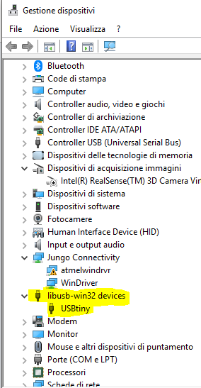
Try to recognize it on Windows OS torught by Device_Manager and check if it’s present in list …