Week5 Group Assignment: Electronics production
Characterizing the machine
Roland SRM-20
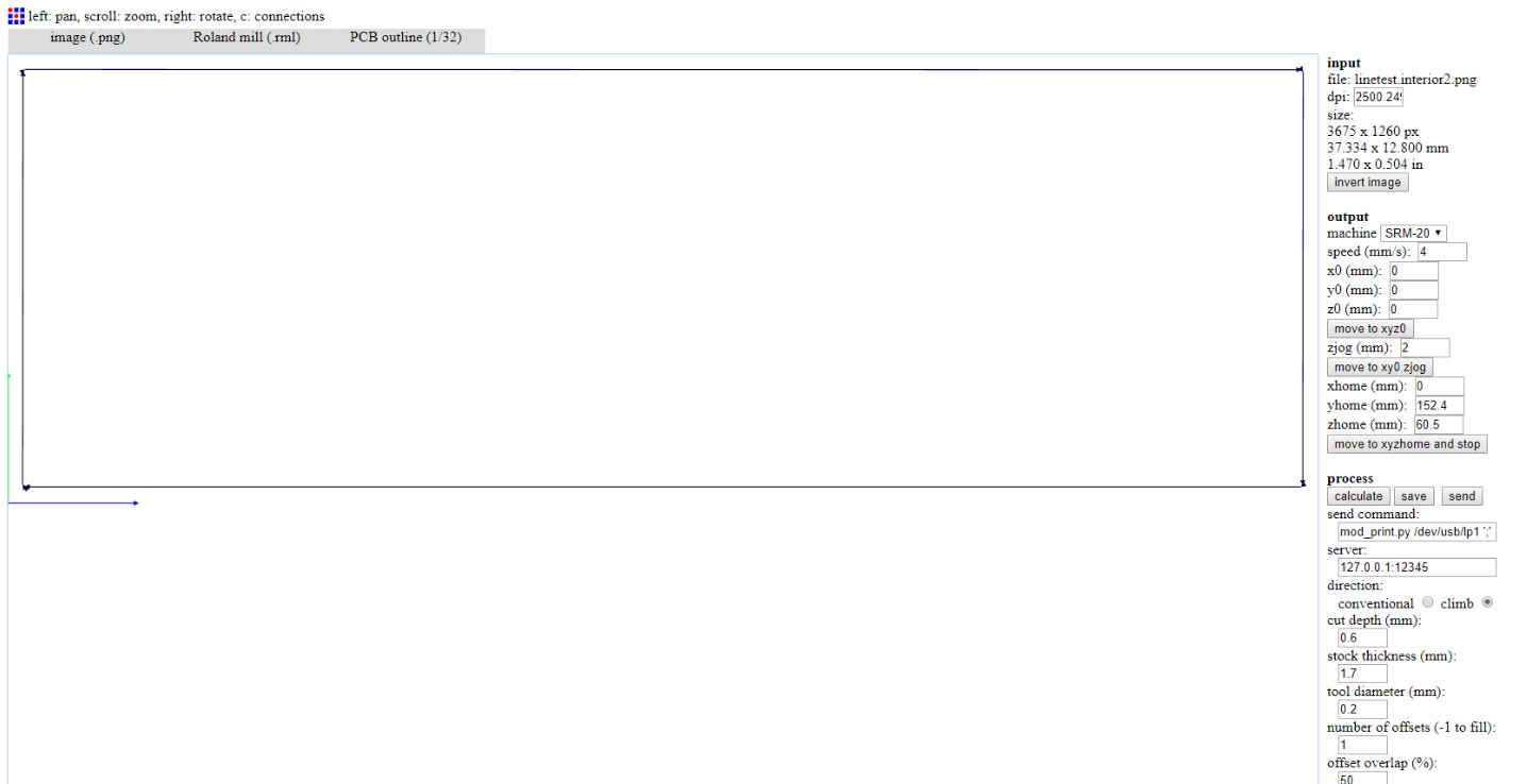
For this week’s group assignment we had to characterize the specifications of our PCB production process on our Roland SRM-20. The software that we used for milling was Fab Modules, online at FabModules and send RML-1 files trought Roland VPanel sender.
HARDWARE
Setup
- Tool: Milling machine
- Model: Roland SRM-20 (203.2 (X) x 152.4 (Y) x 60.5 (Z) mm Working Area)
- Endmill: 1/64 (0.4mm) - 1/32 (0.79mm)
- Materials: FR1 board; 20mm MDF (sacrificial plane)
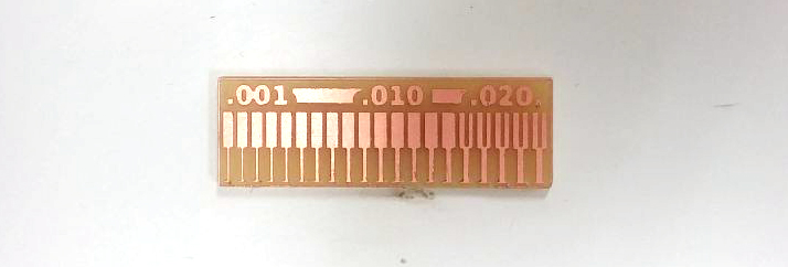
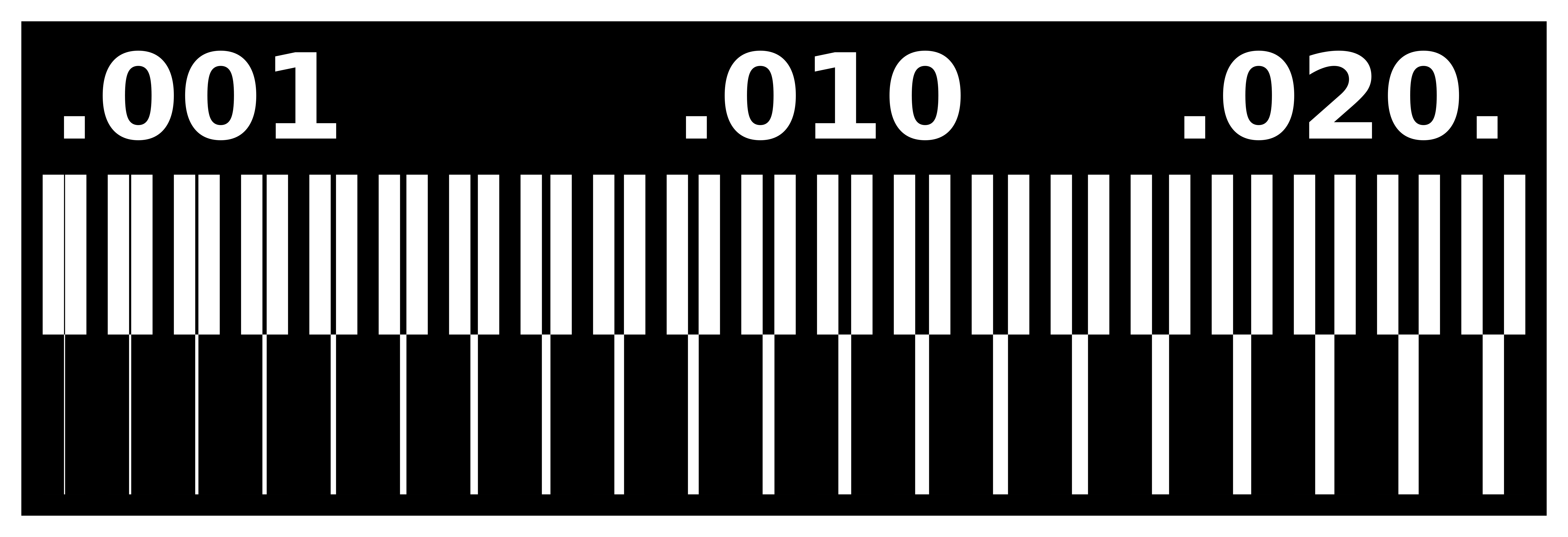
We did a linetest using these two files:
- linetest.png to milling the traces with 1/64 bit;
- linetest.interior.png to cut the outline with 1/32 bit.
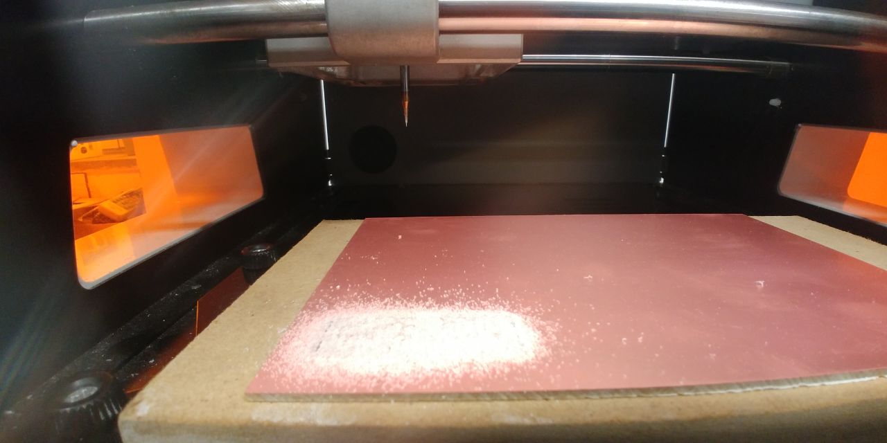
Before attempting to mill we had set the machine as follow:
- prepare a sacrificial plane;
-
using the double-sided adhesive tape, attach the 20mm MDF plane to the table; then attack the FR1 base on the sacrificial plane;
Advice
put the double-sided tape very flat on the surfaces.
-
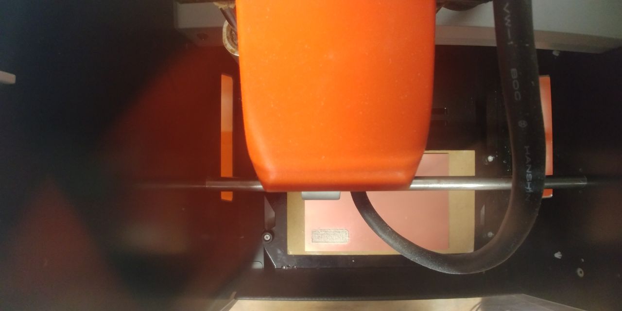
attach the milling bit in the collet and make sure it is 2 or 3 mm from the surface of the FR1;
-
zeroing the Z height, dropping the tip on the plane, making sure that the Z can theoretically get off at least the right amount to be able to mill.
Advice
In case you have not left enough space to get down to milling, the spindle will rise upwards moving as if it were milling.
-
zeroing the X and Y axes starting from the left-bottom side of the FR1 board.
SOFTWARE
The SRM-20 has a good mechanical resolution and the software resolution depend by the type of gcode that the sender manage:
Software Resolution:
| RML-1 | NC code | RML-1 | NC code | ||
|---|---|---|---|---|---|
| inches/step | 0.000039 | 0.000039 | mm/step | 0.01 | 0.001 |
As the smallest track to be milled was 1 mills, we chose to generate an RML-1 code with a resolution of 0.01mm, then we had used FabModules to generate the RML-1 codes:
for Traces —>
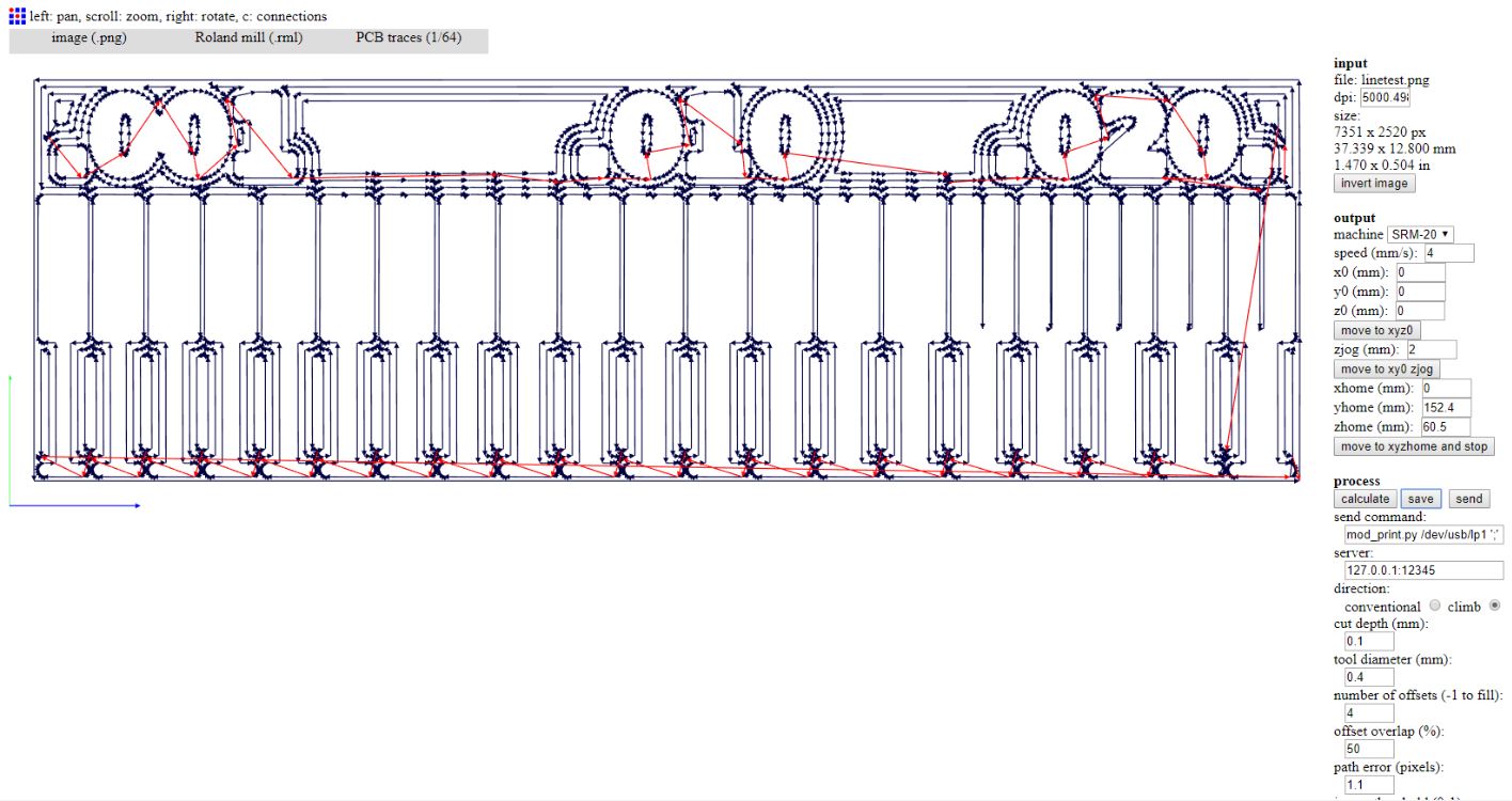
and send it to the milling machine trought by VPanel for SRM-20, we looked for the right setting of zero Z, Spindle (8000 rpm) and Cutting Speed (168 mm/min obtained from 70% of FabModules presetting - 4 mm/s).

The right one is the 2nd to the bottom.
for Outline —>
At that time we were ready to cut the outline, but generating the RML code we have found an error, and we had thinked that Neil played us a joke, why??
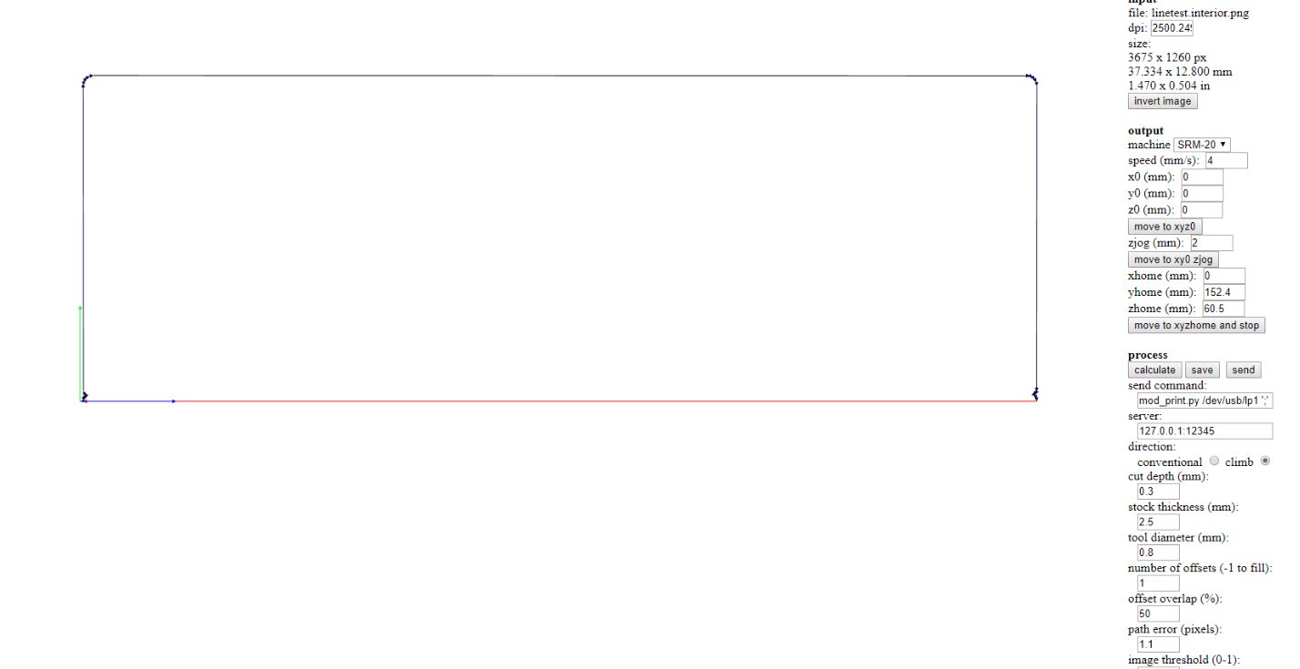
The red line on the bottom represent a Travel, without milling, and this happen because the .png image has a bottom row of transparent pixels.
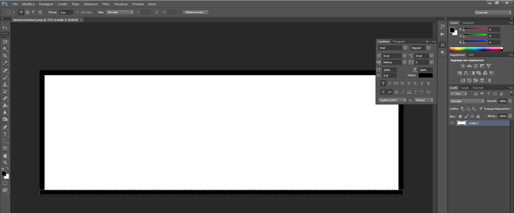
We had repaired the linetest.interior.png with Adobe Photoshop and we had generated a new one called linetest.interior2.png. At this point we had rebuilded the RML code and attached the 1/32 endmill to cut the board.