Week 8 : Assignment
- make something big
In week 8 we are going to learn about Computer-controlled machining. In week 6 we learn about the addictive manufacturing process where we make
the product by adding the layers of the materials layer by layer. Week 8 is introducing the second manufacturing process which is the Material removing process,
in which components are made by removing unwanted materials, metal removing processes are relatively fast.
Week 8's Assignment was to Make something Big using the CNC.
CNC
CNC machining is a manufacturing process in which pre-programmed computer software dictates the movement of factory tools and machinery. The process can be used to control a range of complex machinery, from grinders and lathes to mills and routers. With CNC machining, three-dimensional cutting tasks can be accomplished in a single set of prompts.
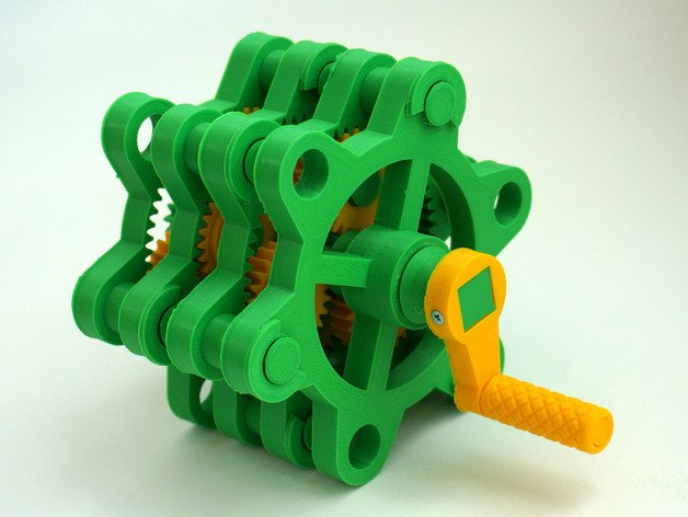
Making Of Planetary Gear
So Assignment Was to make Something big I decided to make a big Planetary Gear mechanism. I cho0se Planetary gear because I want to know how I can use different parameters to make perfect rotating pairs of gears. Gears have so many parameters and they should be accurate in the process of making to have working gears.
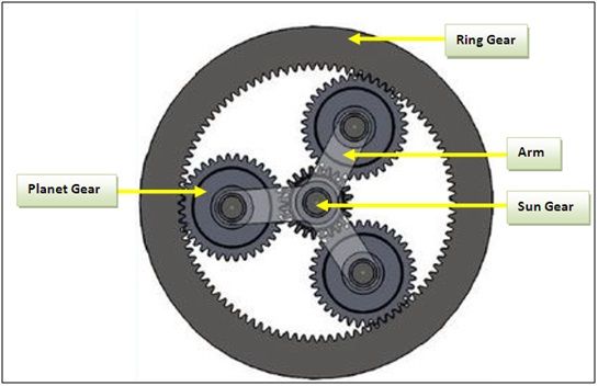
A planetary gearbox is a gearbox with the input shaft and the output shaft aligned. A planetary gearbox is used to transfer the largest torque in the most compact form. Click here to know different types of gears.
Gear Terminology
Law of gearing
The angular velocity ratio of all gears of a meshed gear system must remain constant also the common normal at the point of contact must pass through the pitch point.
If w1 and w2 are the angular velocities and D1 and D2 are Diameters of two gears meshed together then w1/w2 = D2/d1 should satisfy. Pitch point - the point of contact of the pitch
lines of two gears or of a rack and pinion when in the mesh.Click here to know in details about gear types and Terminology.
Basically, Every parameter is connected to each other and that’s why we don’t have to keep track of every parameter, instead we need only values of Module of gear, Gear ration, pitch diameter,
Pitch circle, Backlash, Diametral pith.
Module of gear
The module of gear determines the size of the teeth in the gear.
The module of gear determines the size of the teeth in the gear.
"Module" is the unit of size that indicates how big or small a gear is. It is the ratio of the reference diameter of the gear divided by the number of teeth.
Thus, m=D/Z.
D is the Reference diameter of gear(Pith Diameter).
Zis the number of Teeth.
It describes the relationship between the pitch diameter and the Number of teeth on the gear. For meshing of Two gears Modules of two gears should be same , otherwise law of gearing will not satisfy.
reference Diameter(pitch Diameter)
It is equal to the circumference divided by
Circumference the number of teeth.
Circumference Pitch = Circumference(pi* D(Pith Diameter)) / Number of teeth.
It defines the distance between two points of adjacent teeth located at the same location on each teeth. Click here to know more.
Pitch circle
An imaginary circle passing through the teeth of a gearwheel, concentric with the gearwheel, and having a radius that would enable it to be in contact with a similar circle around a mating gearwheel.
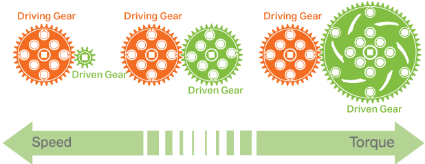
Gear Ratio
Gear Ratio expresses the relationship between a Driving Gear (the gear connected to the input power source, such as a motor) and a Driven Gear (the gear connected to the output, such as a wheel or mechanism) in a system.
Gear ratio is a very important parameter that determines the Applications of the gears, Output speed, Number of Teeth in individual gears.
- When you have a system with a Driving Gear that is SMALLER than the Driven Gear you will increase Torque and decrease Speed.
- When you have a system with a Driving Gear that is LARGER than the Driven Gear you will increase Speed and decrease Torque
Click Here To know more about gear ratio.
Backlash
Backlash, a clearance between mating gear teeth, is built into speed reducers to let the gears mesh without binding and to provide space for a film of lubricating oil between the teeth. This prevents overheating and tooth damage.
Diametral Pitch
It is defined as the number of teeth per inch of the diameter of the pitch circle of gear.
Gear Design in AutoCAD
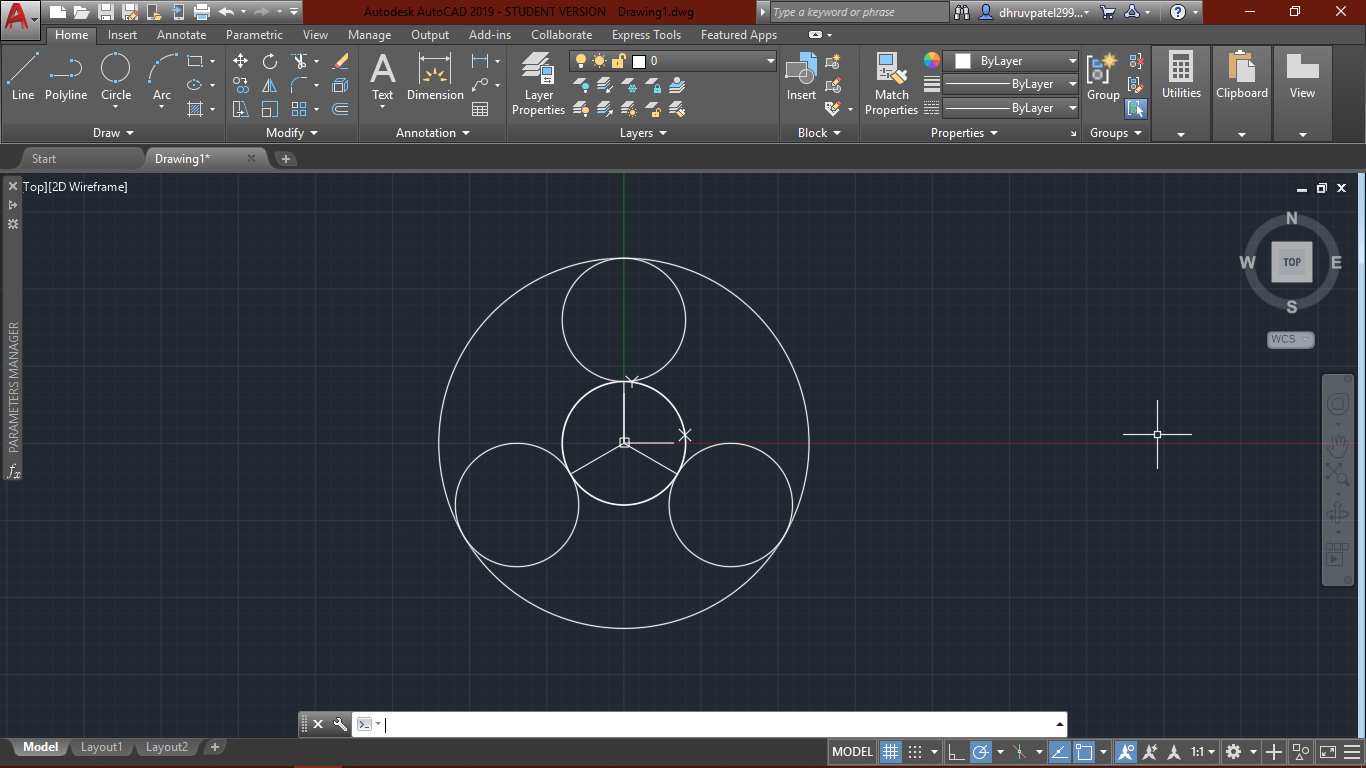
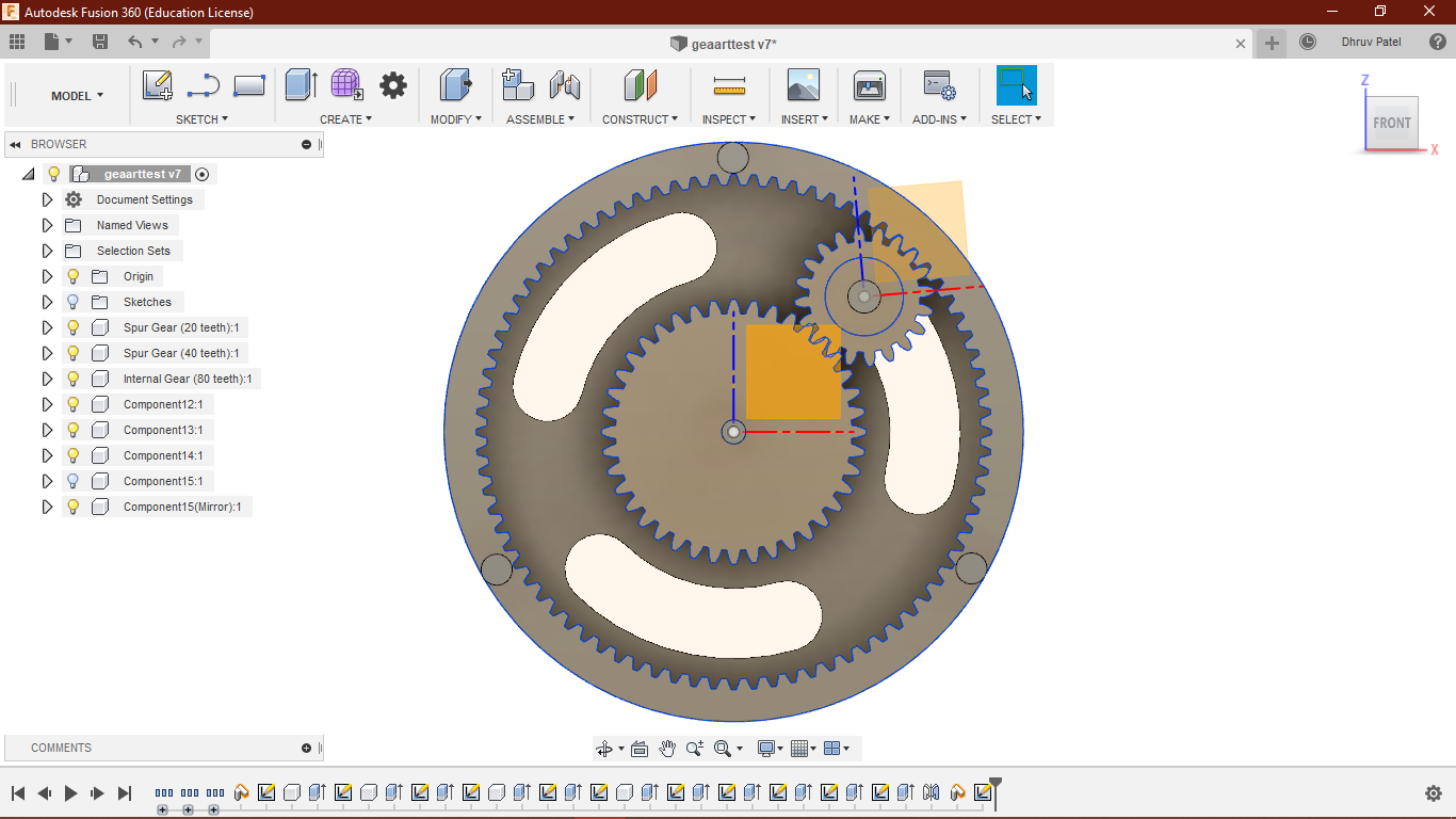
I started designing gears in AutoCAD, since I was going to use 3rd party softwareto design the gears I was just focusing on the pitch diameter only.
I want to make parametric relations between the circles because I was intended to make one prototype first.
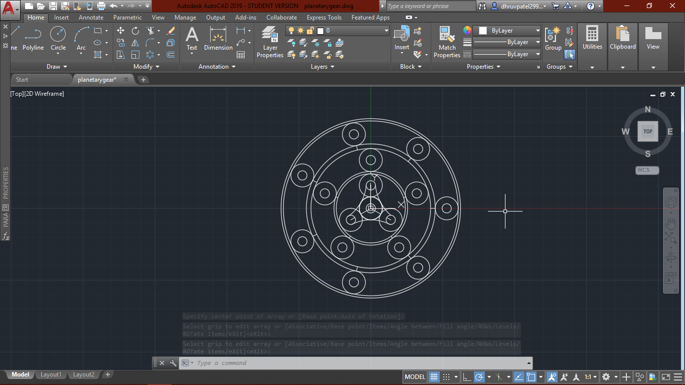
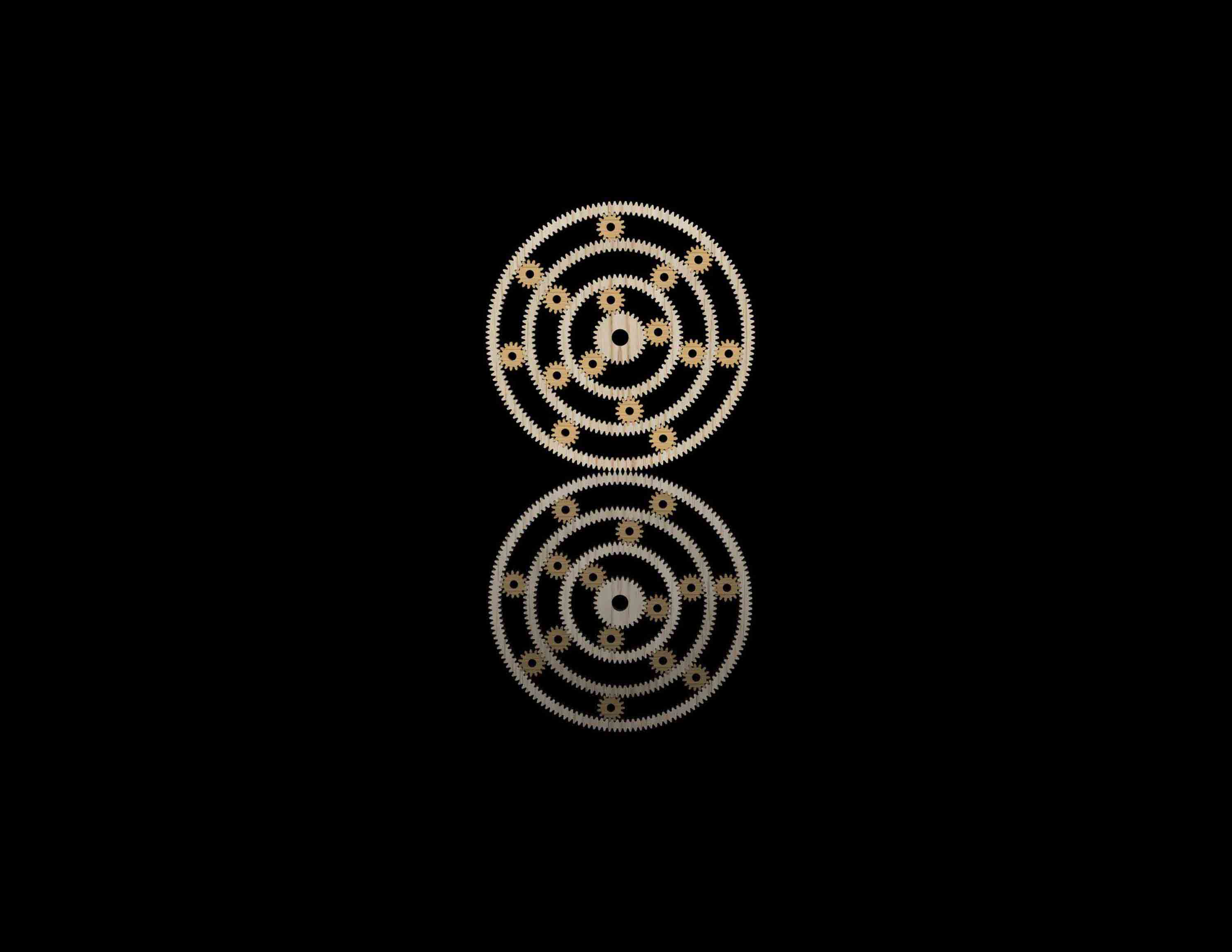
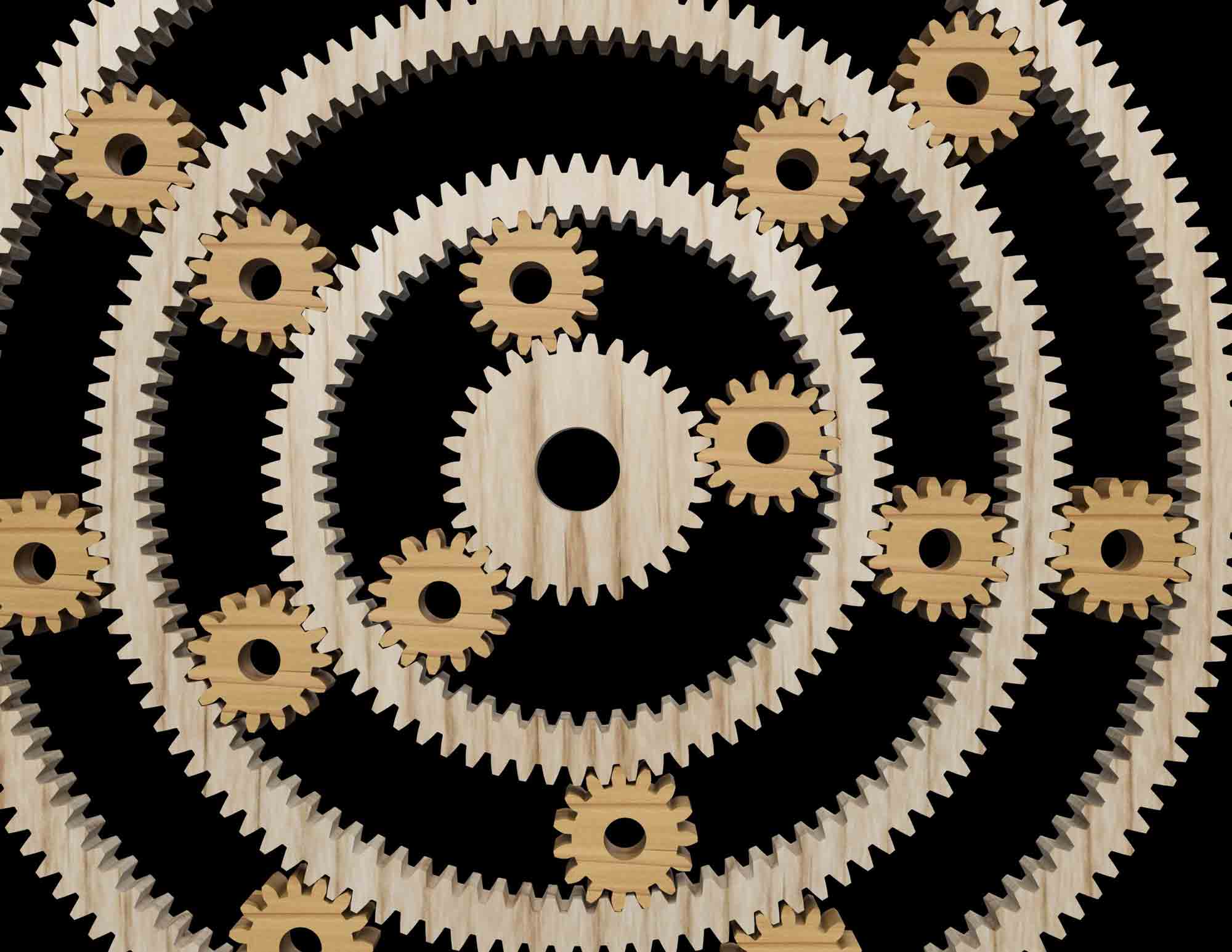
Pitch circles of planetary gear
I started with pitch circles because it makes it easy to predict mesh between the gears.
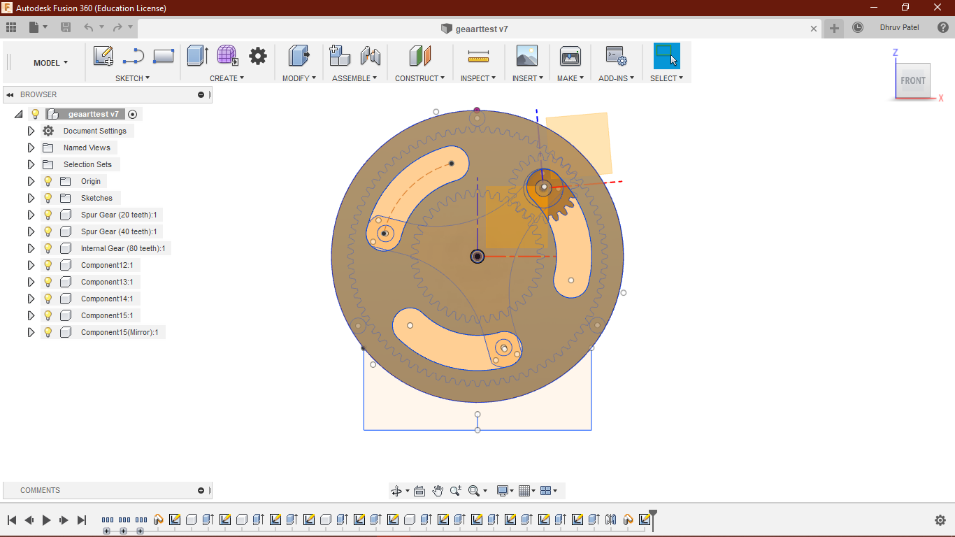
Multi-ring gear
I wanted to try this concept, I was not sure working of it, but I created one sketch anyway. For making these types of designs you should have knowledge of Constrains and Array polar command(Click here). visit Week3 To know about parametric designs.
Paramtric relation
The reason I want to design in parametric is, I can do much faster iterations on my design, I was working with it first time and I know In prototyping I will have some kerfing problems. I was also not sure
about dimensional tolerance in CNC in the real model, I thought it will take many experiments.
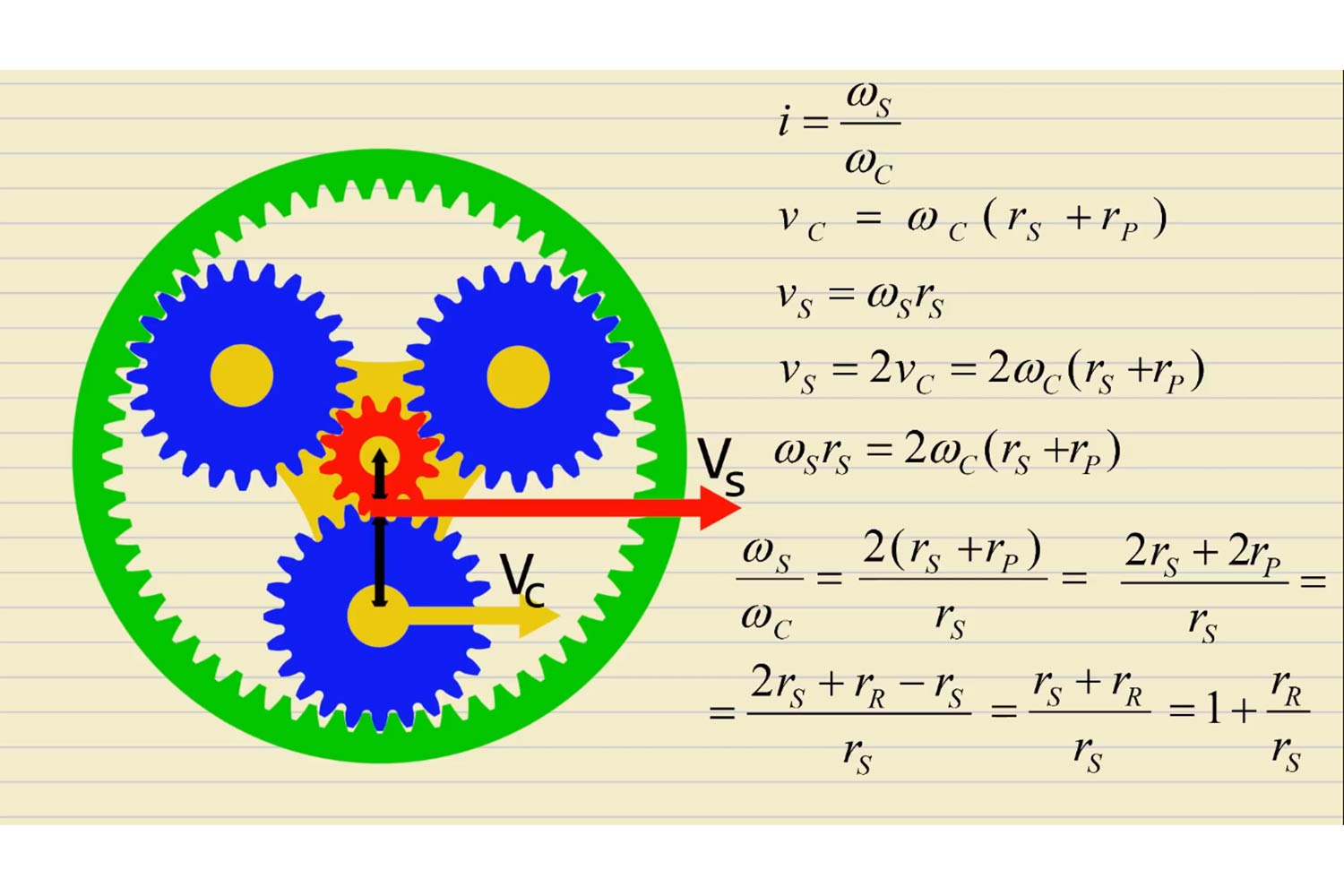
I set dimensions of the pitch circle the way it will give gear reduction of 3, in which the output shaft will rotate one-third of the input shaft.
Image below describes the Gear ratio/ gear reduction relations between the radius of sun gear (s) and the Ring gear (r). Here I am repeatedly talking about gear reduction because Planetary gear is known to reduce the output
shaft speed to increase the torque in drive applications in a compact size, we can also increase the speed to third by taking input as a ring here.
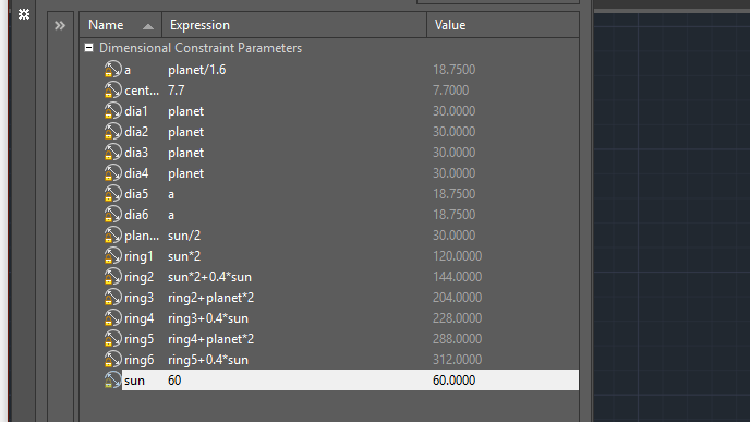
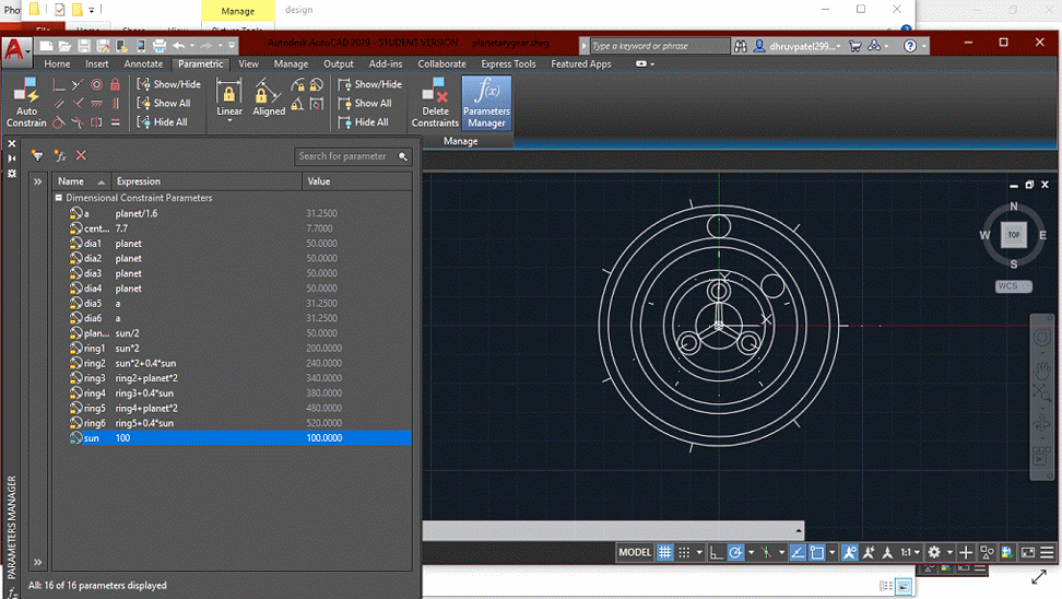
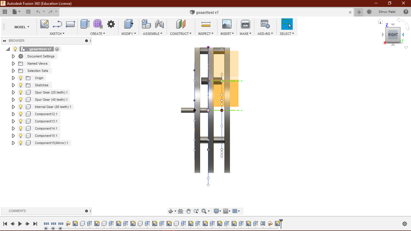
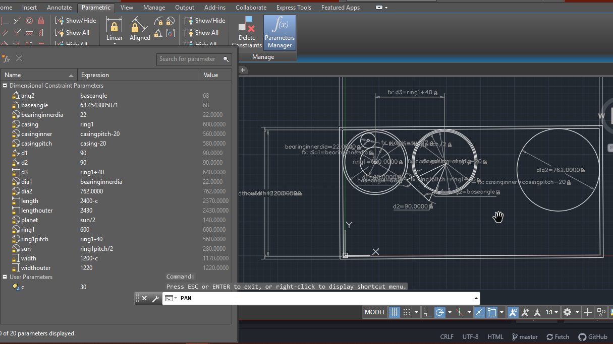
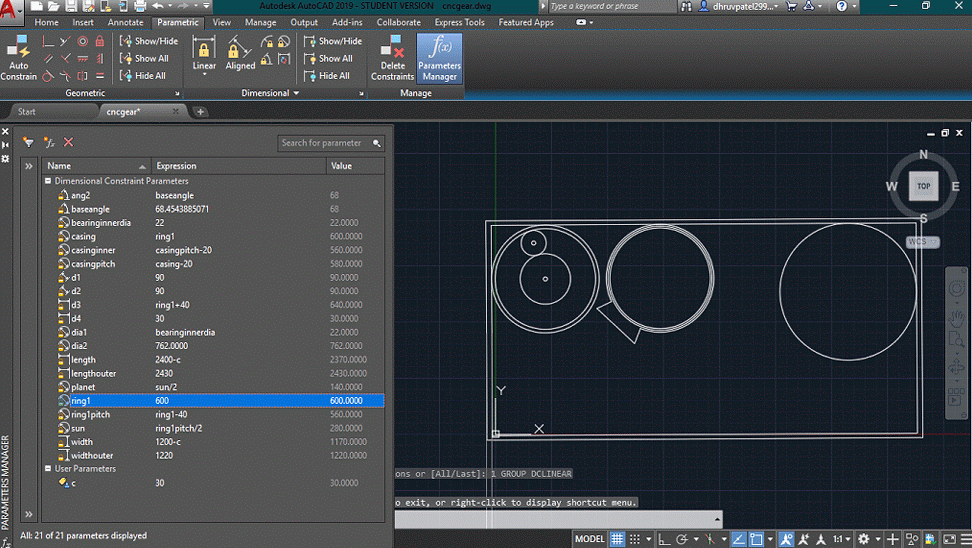
Parameters
This picture shows the parametric relation between gears and ring, my main parameter here is Sun gear Diameter.
Here I kept sun gear Diameter 60 mm for the prototype. It changes the planet and ring gear diameter accordingly. a is the Diameter for Shafts or Wooden dowels (On Axle).
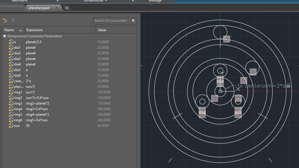
Parametric
You can understand it better below. the original file can be downloaded here.
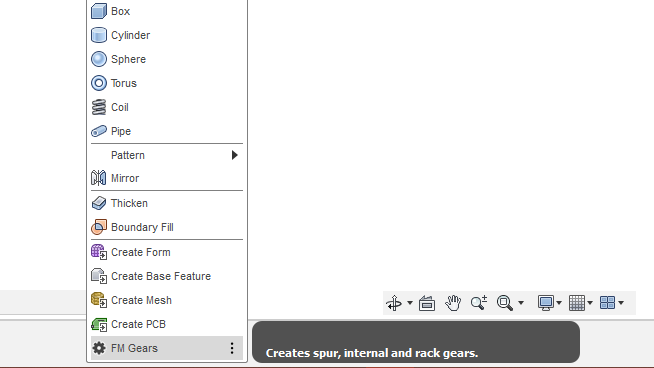
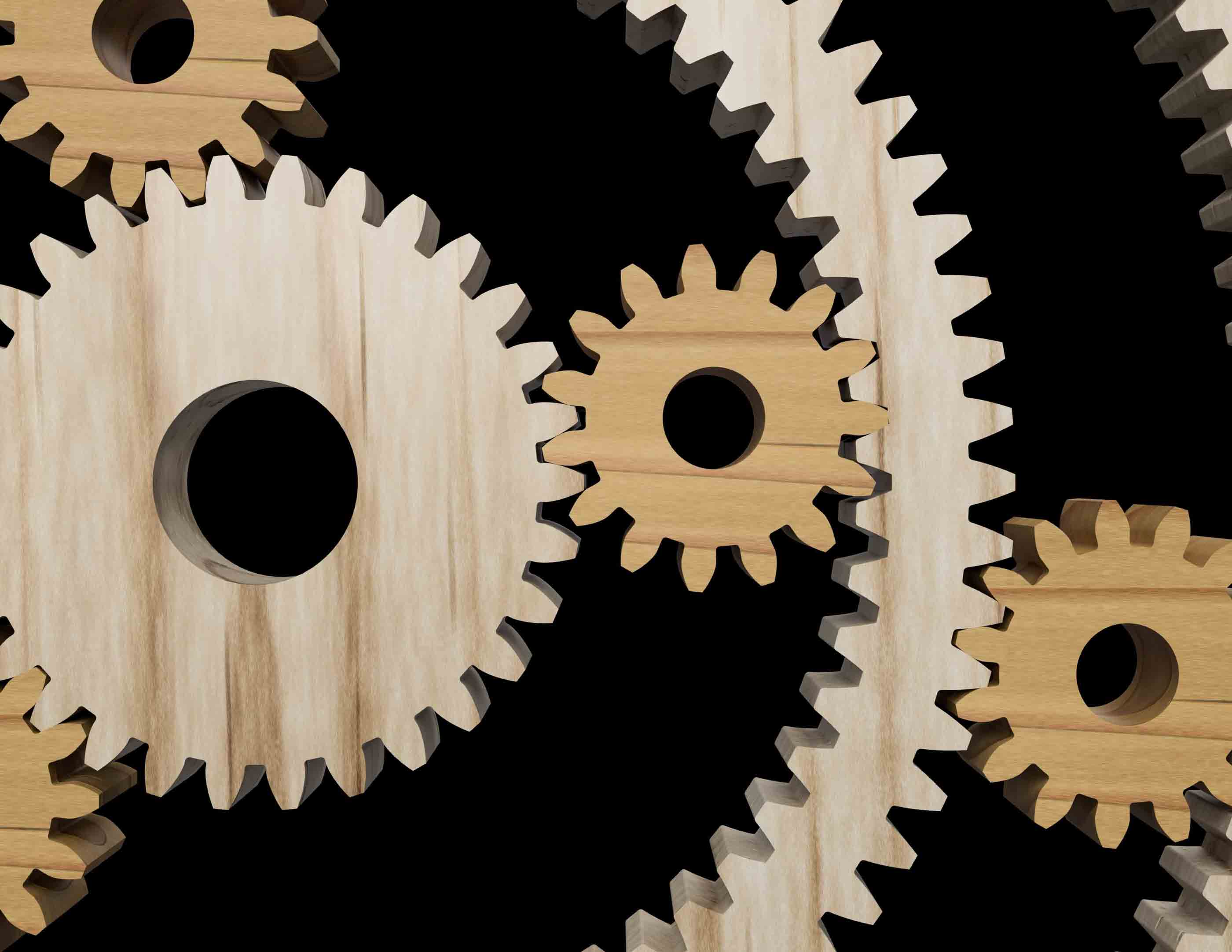
3d Modeling in fusion 360
After Finalizing my parameters I have to design the cad model for the proper way of understanding in joining and frame of Gear assembly. Since it was a critical and time-consuming part to make my own teeth design I decided to take the
help of software or plugins.
I found good web pages and software which can help in gear design.
All links are great for gear design but I choose the FM gear plugin for fusion360, reasons were they have some design limits or their full versions are paid or they do not support internal gear type. fusion360 has also a Plugin for gear but only supports spur gears not internal.
FM gear plugins
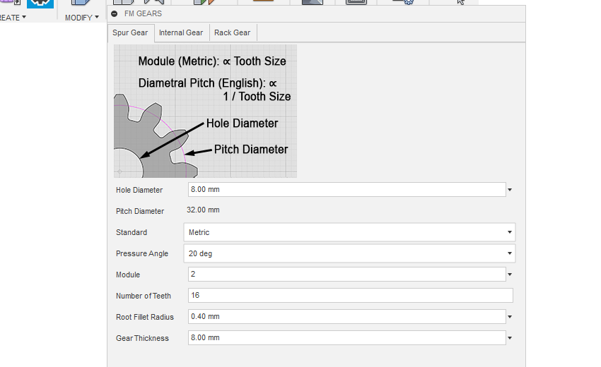
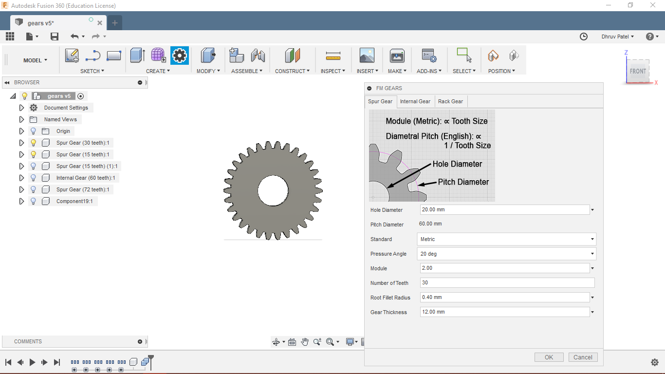
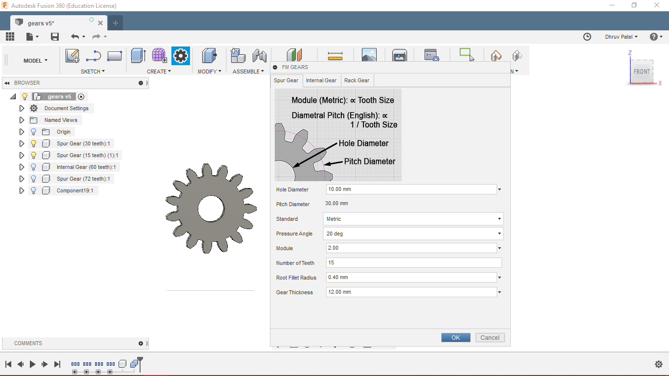
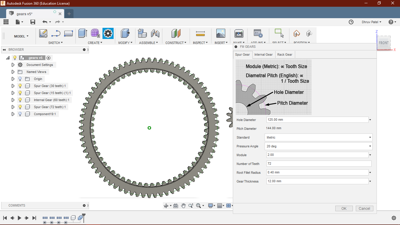
So, I used to plug in for the fusion360 " FM gears" for generating gears. To run the script go to the "Add-ins and script" infusion 360 and ad FM gears, Then open the FM gears from create menu.
Parameters
These are the parameter You can give on the FM module, Everything else will be controlled by the inter-relations of parameters then. I kept the Unit system to standard Metric because I am not familiar with the
English parameter.
Pressure angle: I kept the pressure angle 20 degree here. there are three standard pressure angles 14.5, 20.25.
Pressure angle: Pressure angle in relation to gear teeth, also known as the angle of obliquity, is the angle between the tooth face and the gear wheel tangent. It is more precisely the angle at a pitch point between the line of pressure (which is normal to the tooth surface) and the plane tangent to the pitch surface. The pressure angle gives the direction normal to the tooth profile.

Lower the pressure angle higher will be power transmission( in terms of pressure angle). But higher pressure angle will give good loading ability(Torque) and increase the stress as well.
Since I have an application of torque and I did not want my teeth to break I kept it to 20 degrees.
Here module will take control of the number of teeth, the higher the module laser the number of teeth. but I should be kept at an optimum value to have smooth power transmission. I kept Module: 2.
Sun gear
Starting importing gears.
Ring gear
Inner ring
There is one judged here. I wanted to have teeth both sides of the ring but FM gear has not to feature like that so I made a different outer ring of which inner diameter less big than the outer diameter of the inner ring.
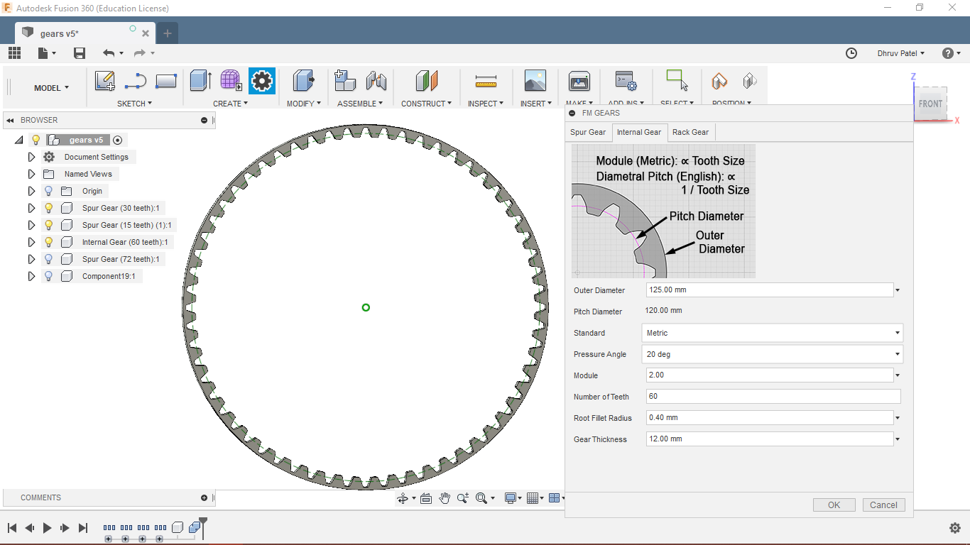
Second Ring
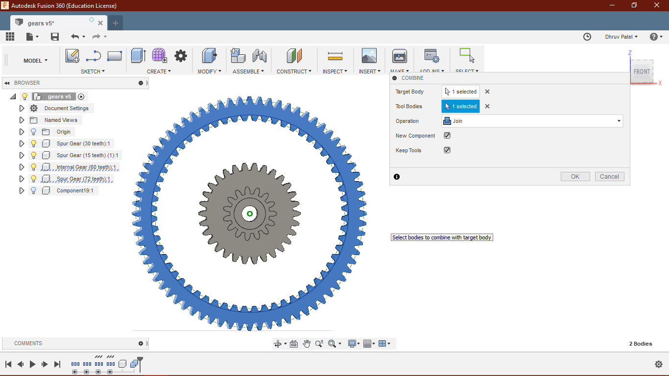
Combine Tool
Then I used a combined tool to join both bodies.
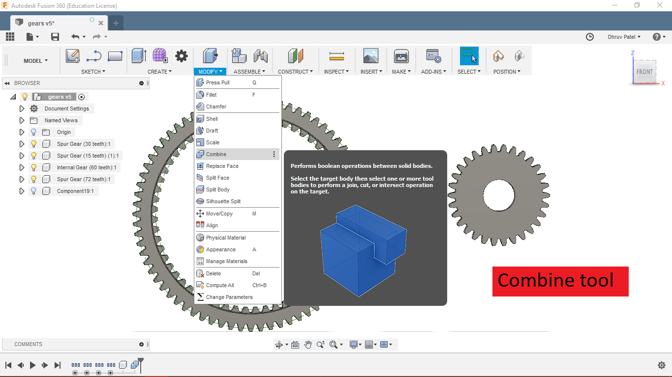
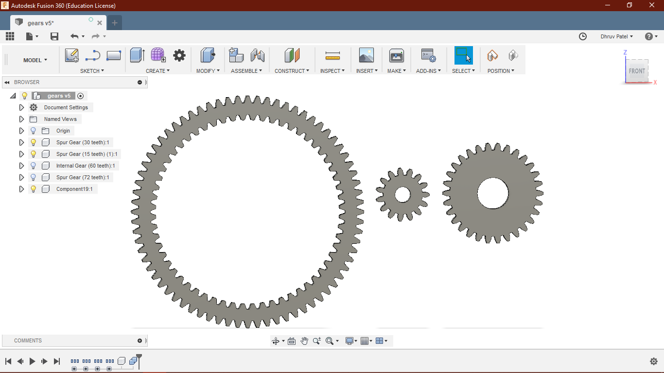
Combining Two gears
Setting up three gears
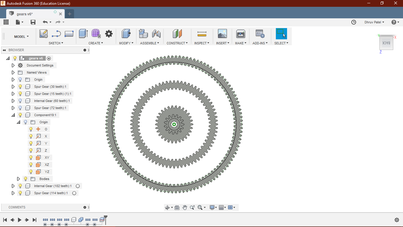
Multiple rings
I was told multi-ring gear will be very difficult for This time limit, because not every gear can be free in designing some of them needs to be fixed with the frame itself. Since I had a hard time visualizing the mechanism in this design I decided to go for the first stage. so I went for only one stage Planetary gear.
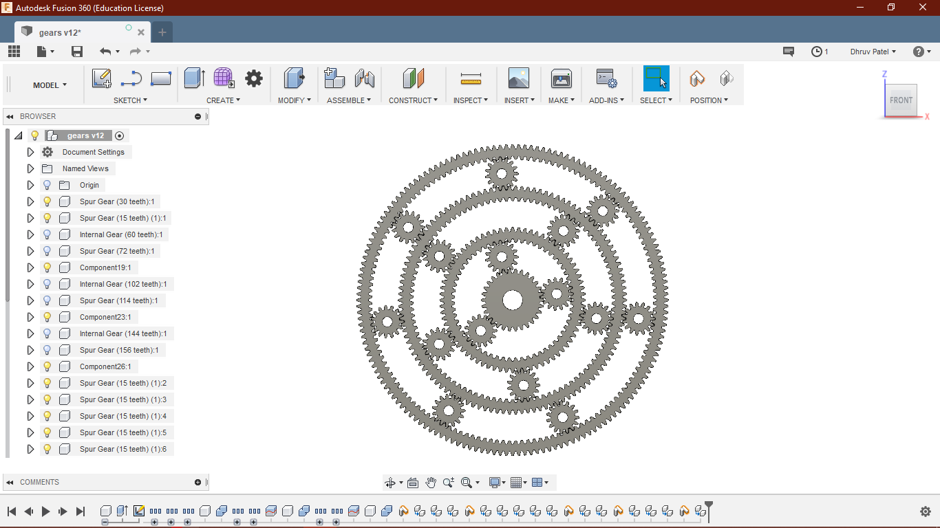
Renders
I render it anyway by hoping I will try it one day. You can download original files from Here.
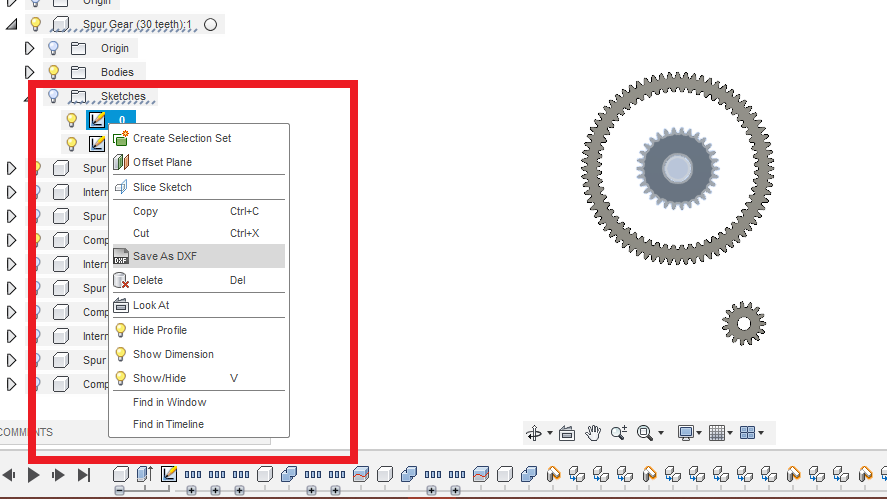
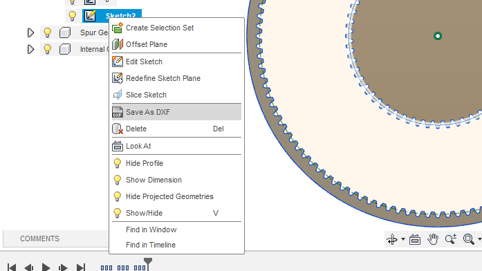
Making DXF files
Making DFX files from the Fusion
Another reason I want to work on fusion is I can directly export the DXF file from the sketch itself. We can export the .DXF format from the sketch.
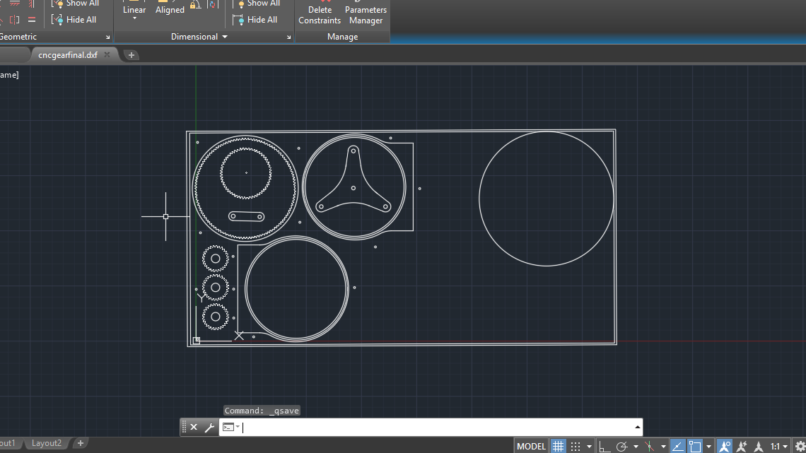
Import it to Autocad for cutting.
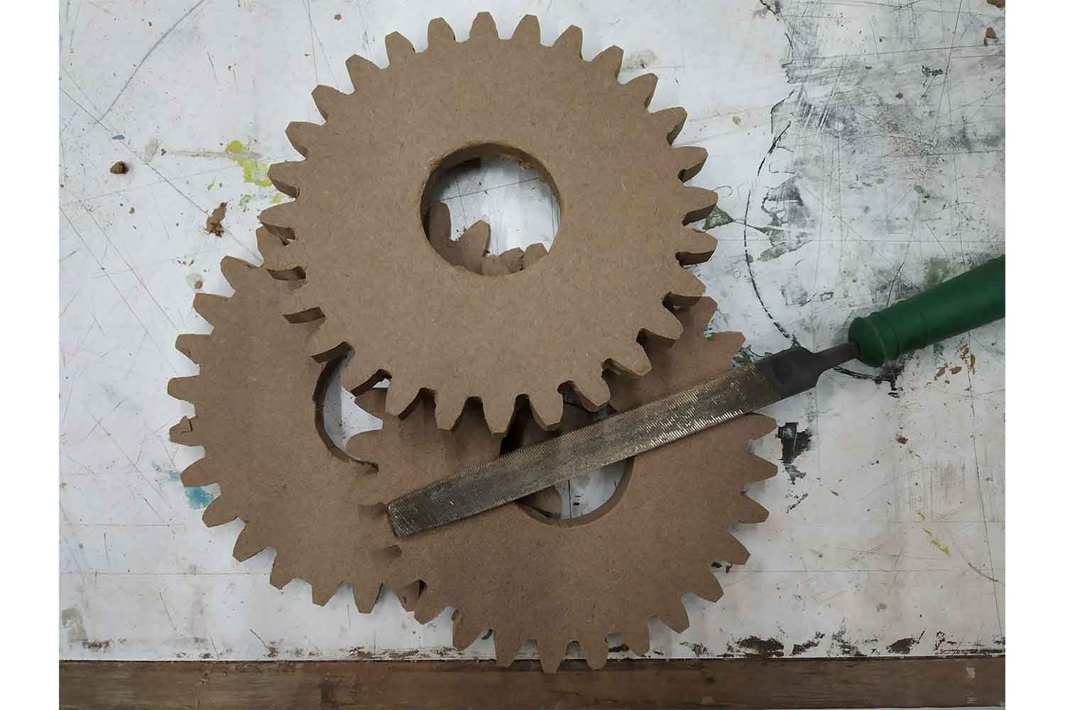
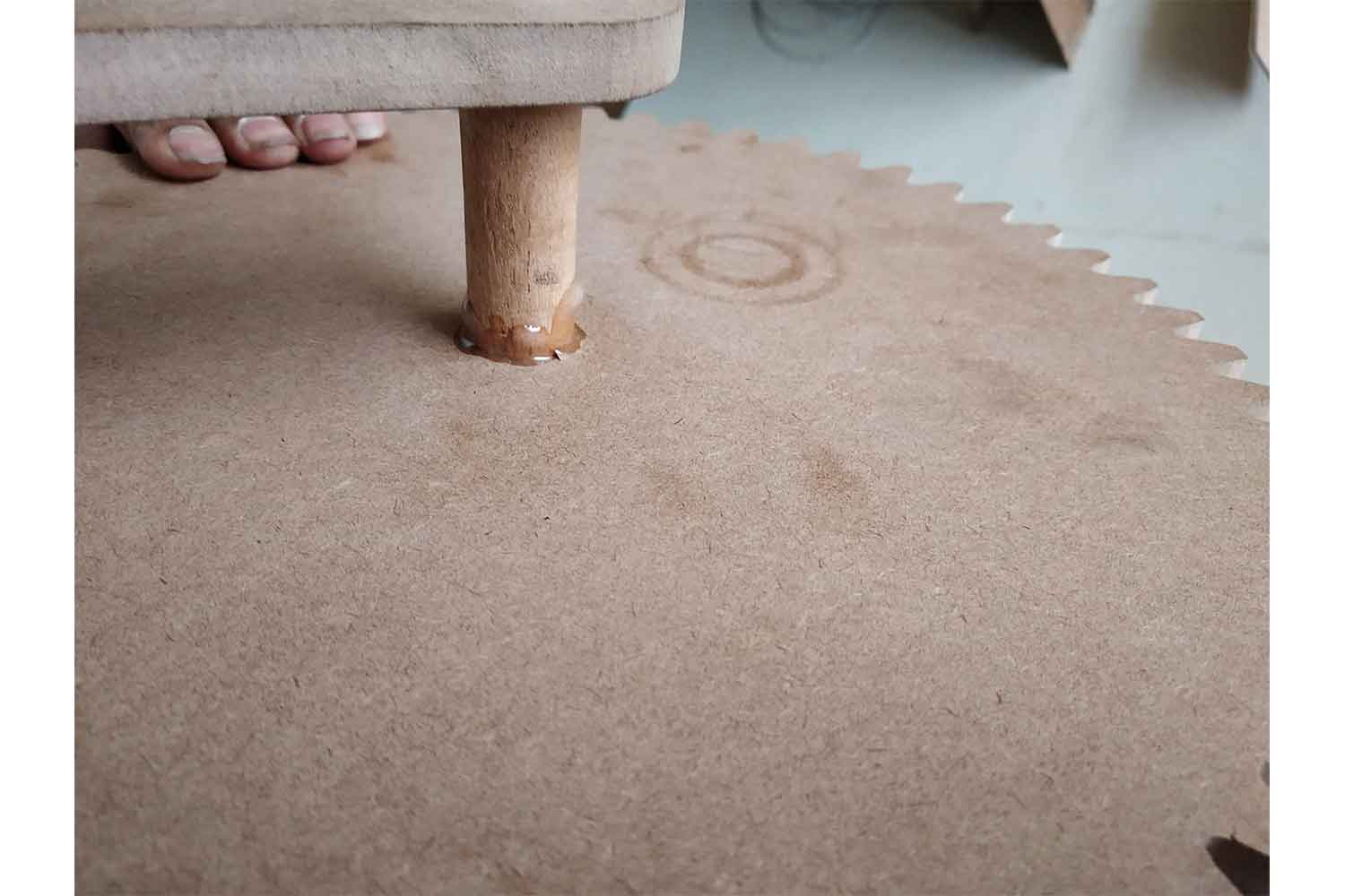
I have to make one prototype before going to CNC. you can see the laser cutting procedure on week4. the original file can be downloaded here.
output
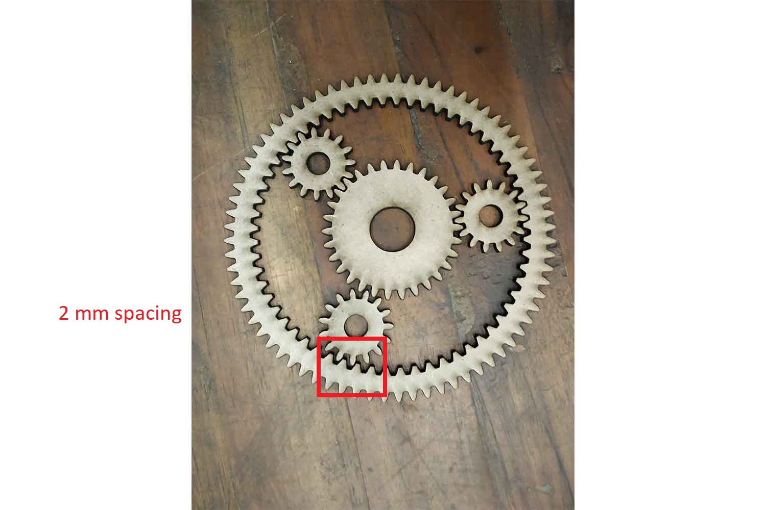
I am using MDF 3 mm for prototyping.
Power = 55%
Speed = 15 mm/s
In laser cutting, kerfing is going to be sure. I got a difference of 2 mm in teeth spacing since I got stuck in pitch diameter I assume it would be 0.5 mm for each gear and component pith diameter(Increased ) In laser cutting kerfing is going to be sure. I got a difference of 2 mm in teeth spacing since I got stuck in pitch diameter I assume it would be 0.5 mm for each gear and component pith diameter(Increased Diameter by 0.5 mm).
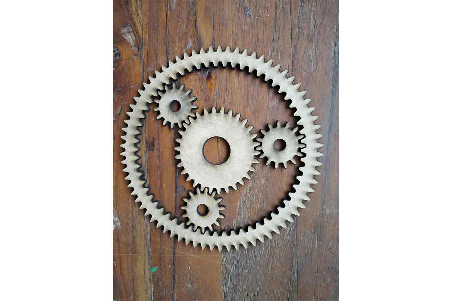
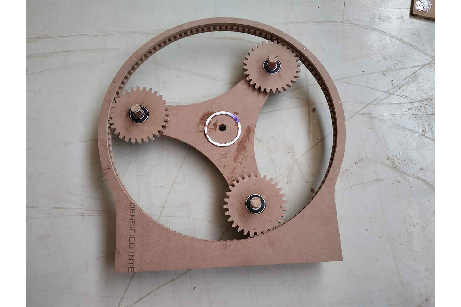
Second try
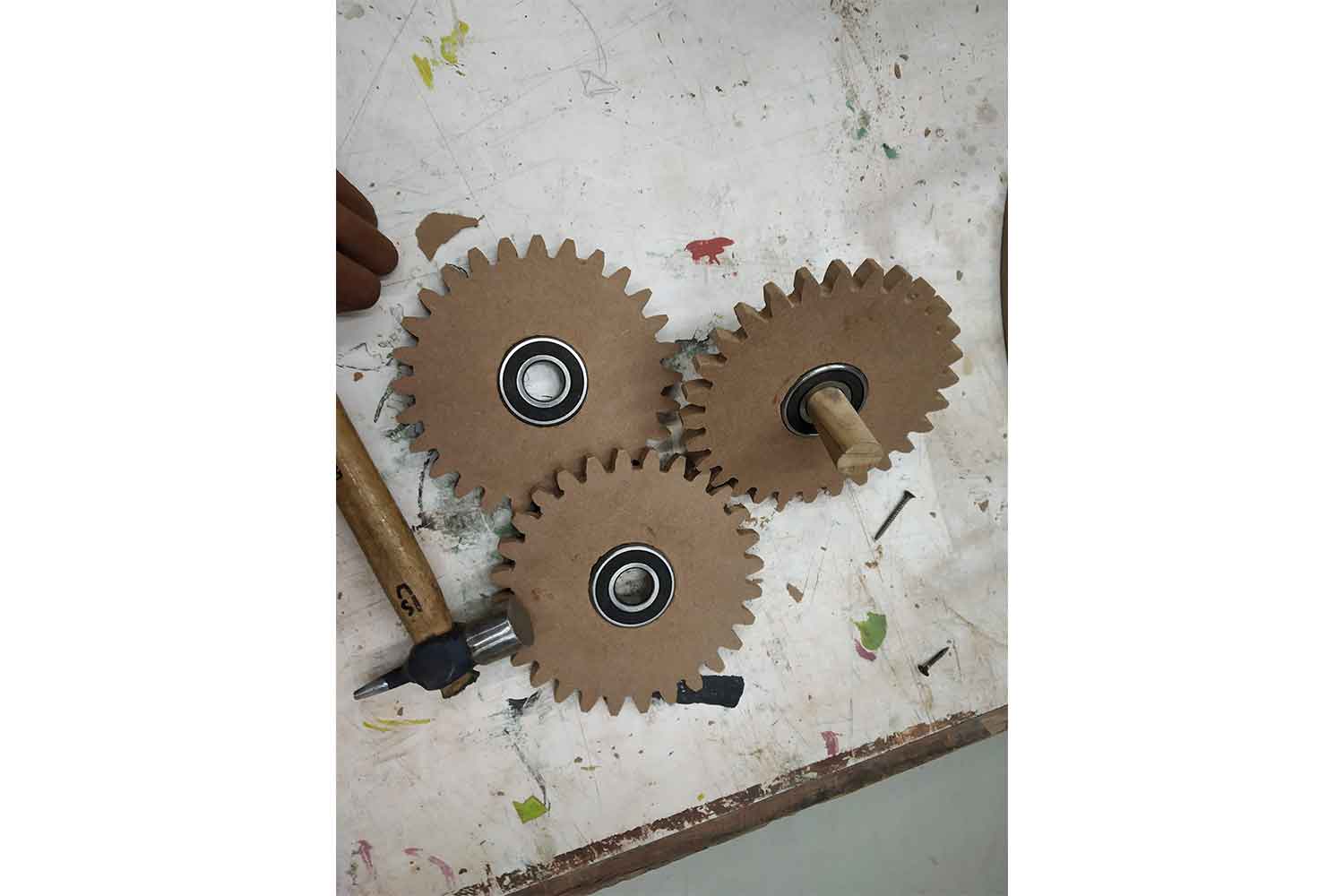
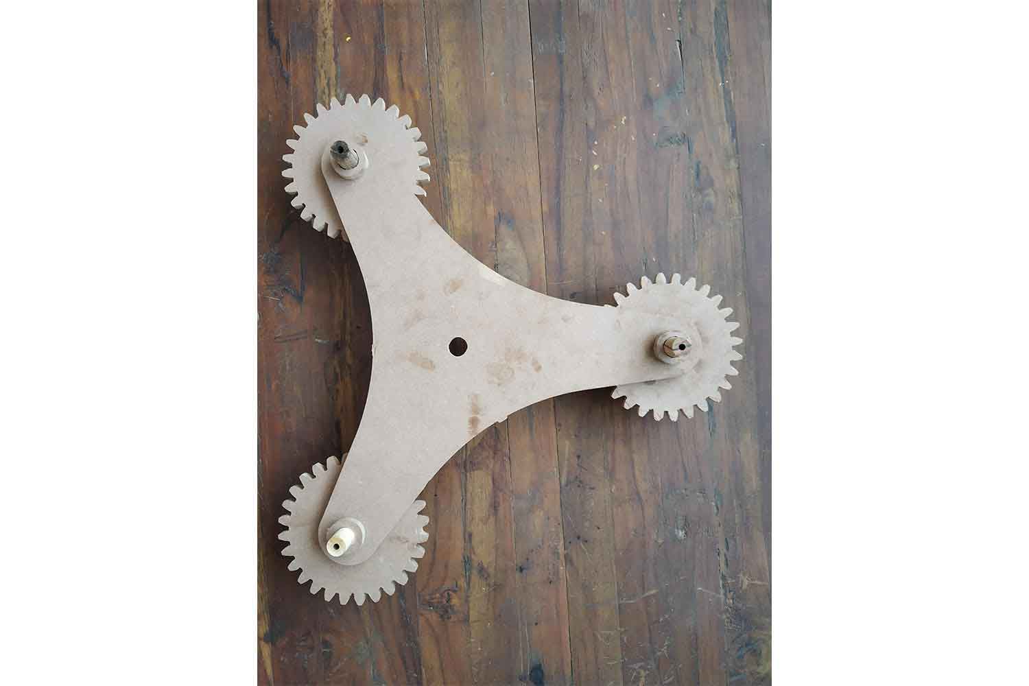
It came out perfect. now I can work on full gear assembly. Then I made an axle for planetary gear, it will help to get output.
Nylon Screws
I was going to use nylon screws for my output and input shafts and replacement of dowels for prototyping.
Redesign of Gear box in fusion360
since I know which pitch diameter will be good for me I went for a framework of gear, big help from my friend Samiul Hoque for clearing my concept about
gear frame, I have to decide which gear I am going to fix and I fixed my ring gear with frame.
go to Week3 here to know about
fusion360 tools. Original file can be downloaded here.
prototype
laser cutting
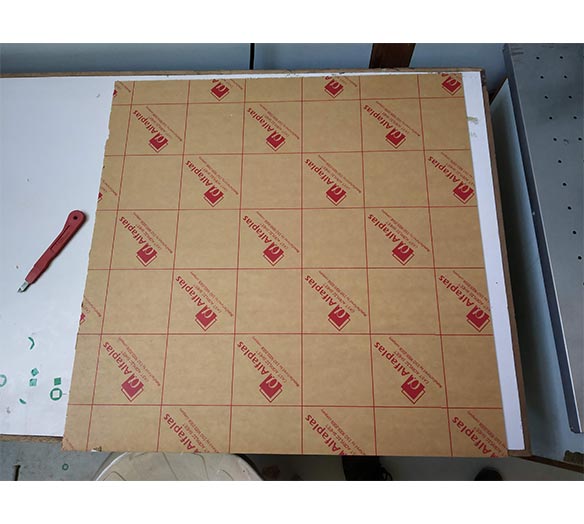
I was using my labs recycle materials, since my MDF sheet was finished I had to do my work on Acrylic.
Finalizing Perfect diameter
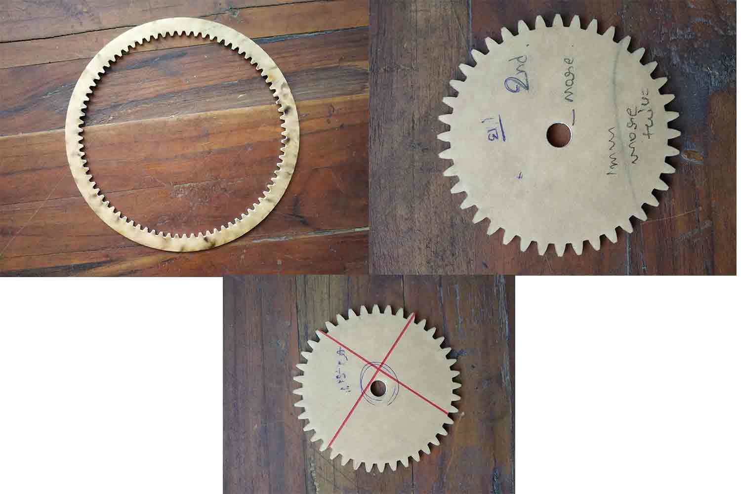
I have to make 3 prototype cuts for my design.
First one :
I gave dimensions same as mdf sheet to test. (0.5 mm additional).
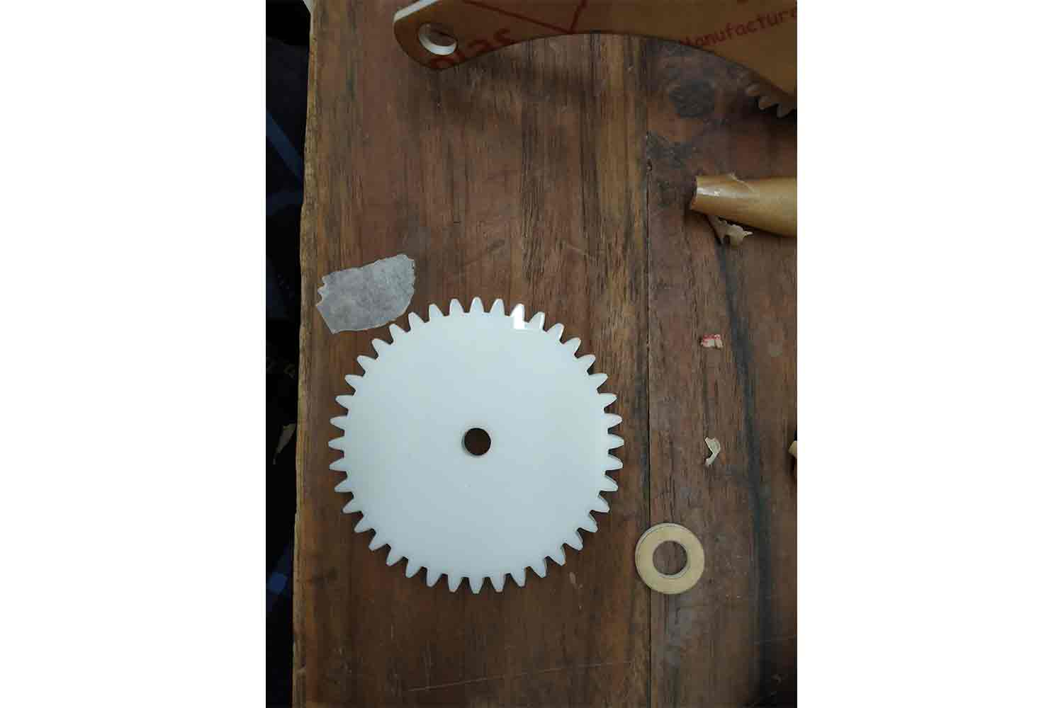
Sun gear : 60.5 mm
planet gear : 30.5 mm
Ring gear : 119.5 mm
I knew it might work because it was designed for MDF but I want to know how much it loses. I found it was spacing 1.5 mm on one side. for the component that I directly added 1 mm in sun and planet and decrease the same from the ring.
second one :

(1 mm additional)

Sun gear : 61 mm
planet gear : 31 mm
Ring gear : 119 mm
And it was a bad idea, now Ring gear, now Ring gear was small for sun and planet to assemble, I hardly placed planet in assembly but it will surely break if I try to force it in more then a few times. so my two models fail. but I found one solution though. I Checked if I took sun and planet of version 1 and ring of version 2 I was giving perfect result. not too tight not too loose.
Third one :

Sun gear : 60.5 mm
planet gear : 30.5 mm
Ring gear : 119 mm
It worked, I was marking every version so did not get confuse on them. Then I made three sets of dimensions of last one to glue them and made one frame to support the ring gear.
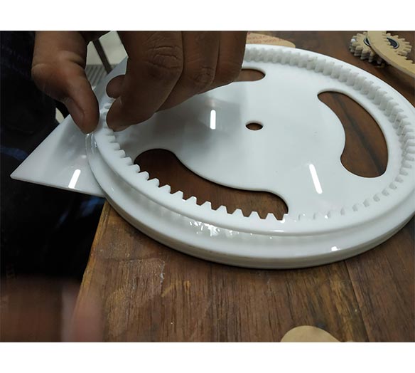
Gluing gears with chloroform
I was never good at joining the stuff, here my friend Maharshi Solanki is helping me to glue the gears properly. Nice making Making experience though.
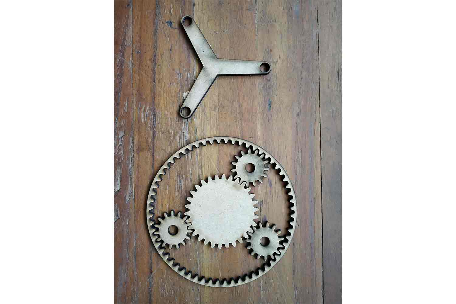
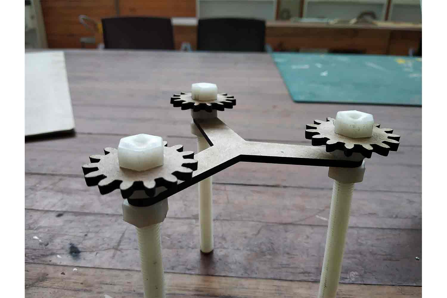
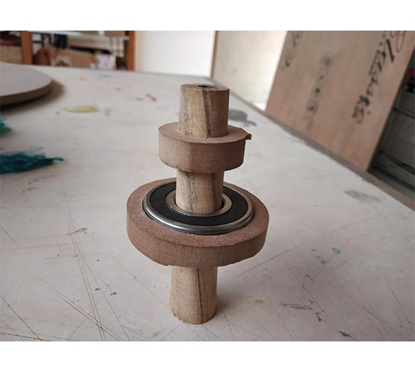
Clearance
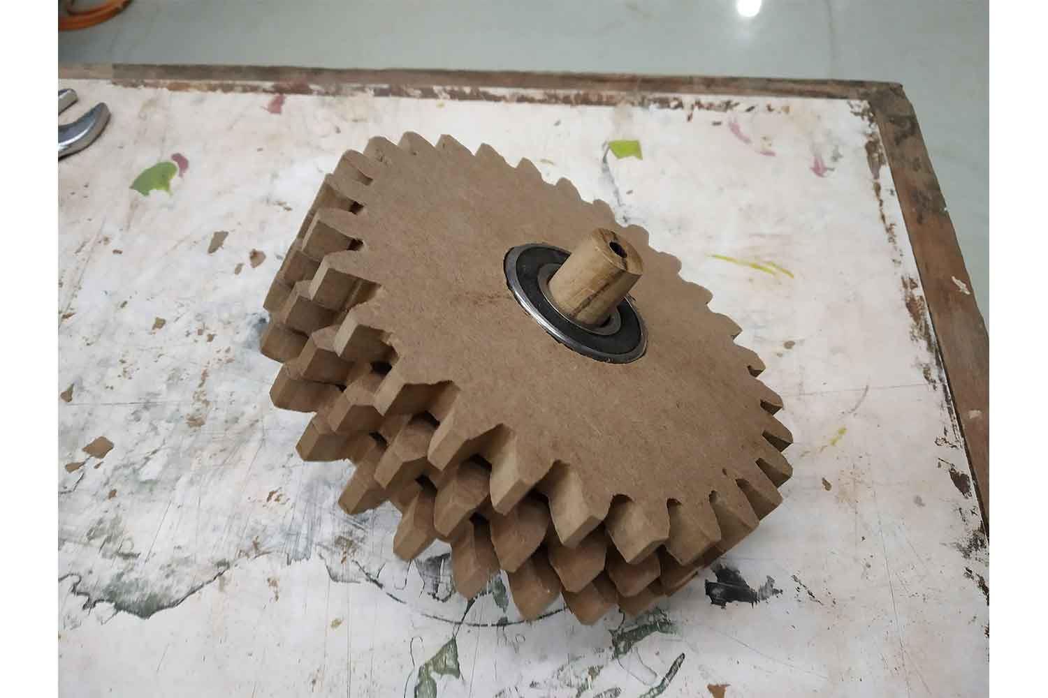
I also build an axle to support the planetary gear. I gave them some of the clearance which waste cuts and dummy rings. I also place bearings between the Shaft (Nylon screws) and Planet gears.
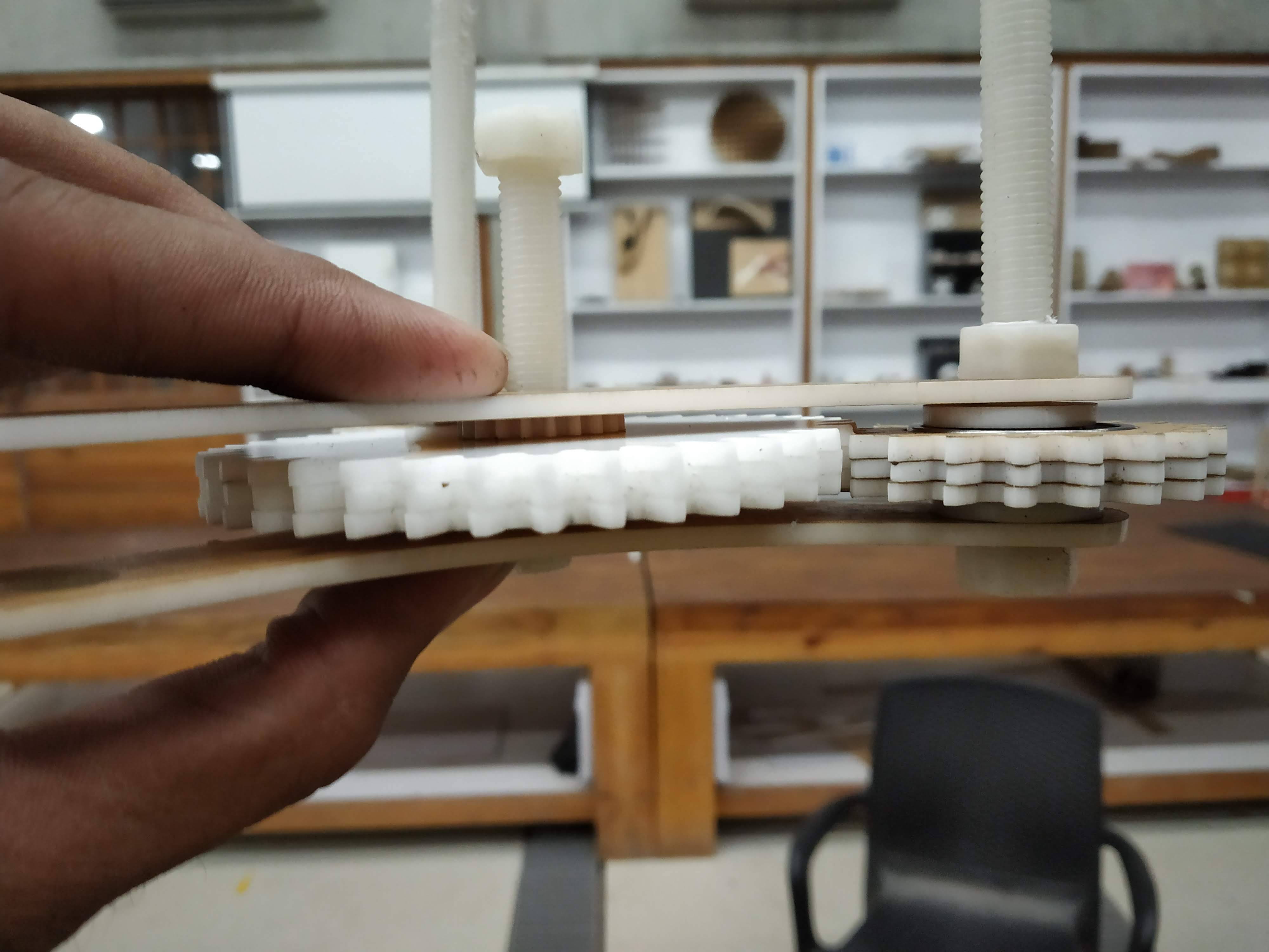
Working mechanism
It was so nice to gear working, it was not possible without the help of Maharshi and Samiul.
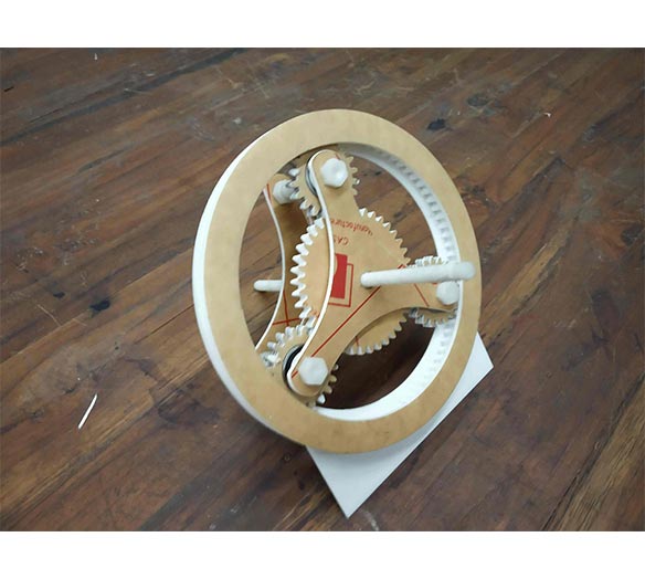
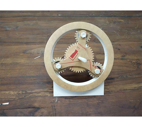
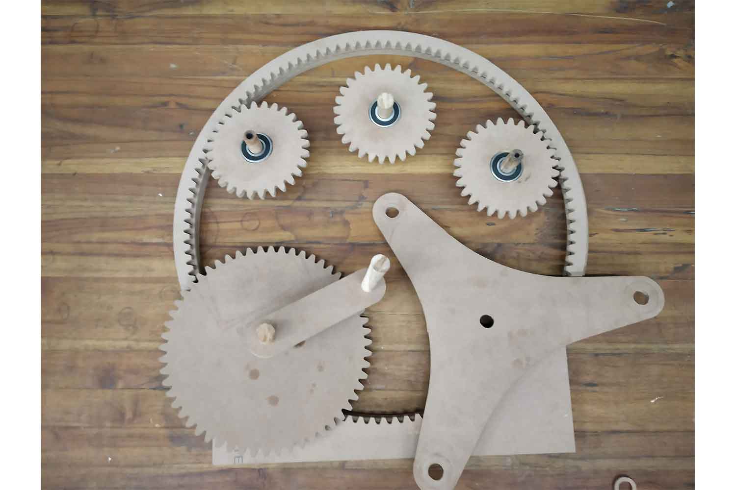
final assembly
My prototype was ready I can work on my CNC design.
Things I learned
I get to learn during prototype making, it clear my idea halfway I also found which things I should take care of in my final design for example.
- I forgot to make clearance gap between frame and inner ring, thought I made some clearance in my cad model I forgot to make it on model.
- I have to think about some wood dowel or metal rode which can carry the planet gear because in big model it will be some load Constrains.
- and for output shaft, I am going to place one disk and want to do some 2.5 d carving on it with CNC
CNC MODEL
After analyzing the Prototype I started working on my CNC model.
For CNC models I wanted to use these materials efficiently, and instead of two axles back and forth of the gear assembly, I decided to use only one axle. it will definitely help me save the material and I can use it for
another CNC work.
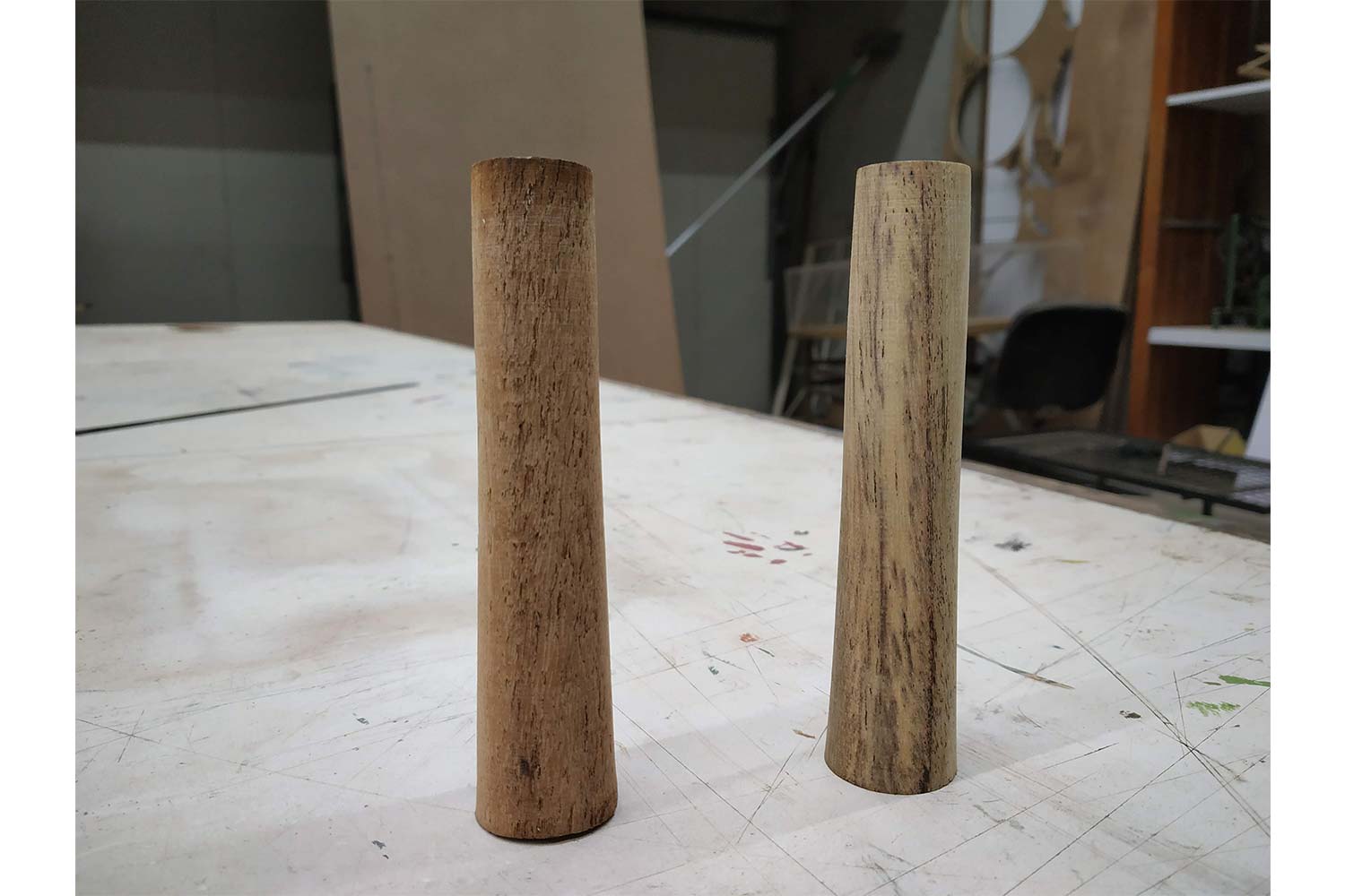
dowels
So if I wanted to use one axle, I need to use taper dowels in which, Wedge Action will help to Fix the Bearings with the help of Friction. Click here to know about Wedge Action. My dowels have varying Diameter from 18 to 21 mm.
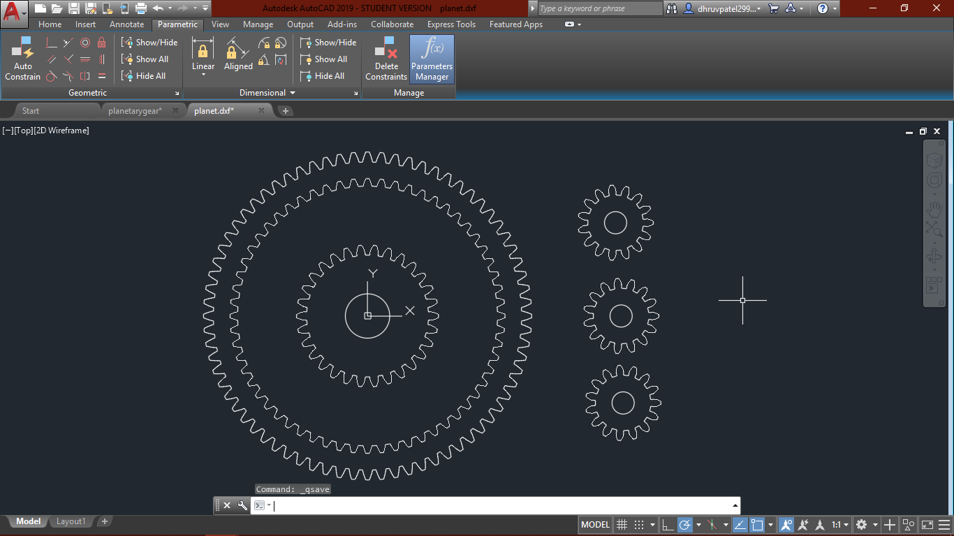
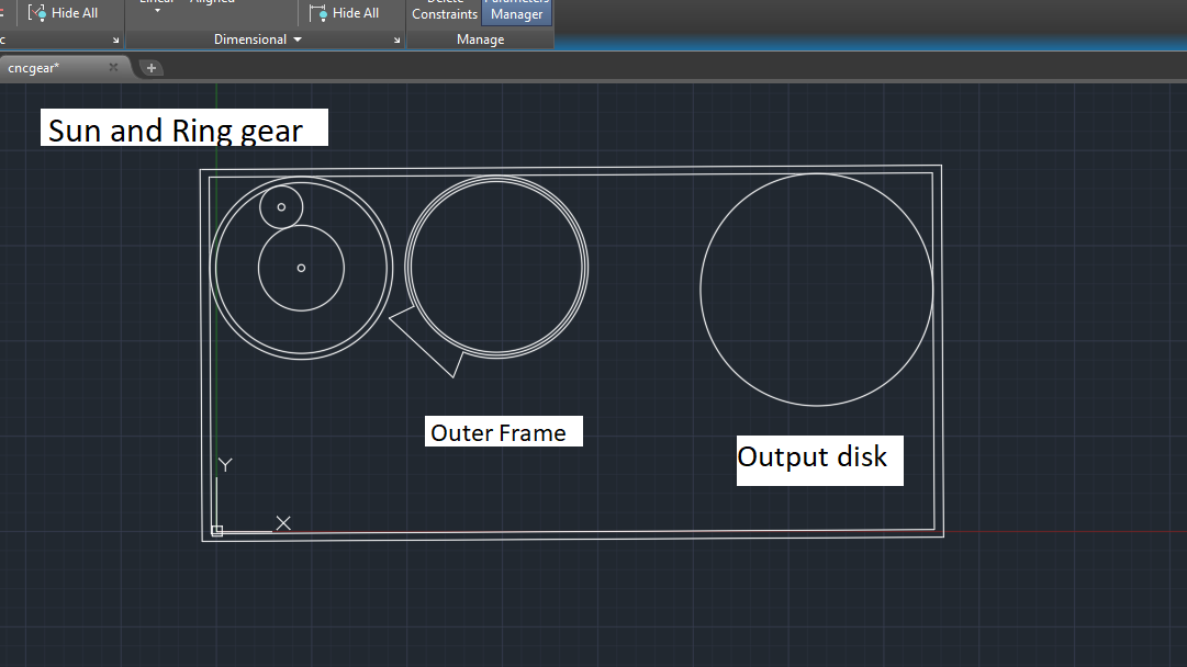
Creating CNC Files
After fixing my dowel Dimensions around 20 mm (in the center), I started designing for the Main gear files for CNC cut. My CNC file is also parametric. so I can have good flexibility in design changes. Below are the
Parameters and the relations I gave on Desing. the design procedure is the same as I explained in prototype file. Here I used pitch circles as references , according to it I am going to generate gear profiles.
I want to cut the output disk later, if sun and ring gear will work perfectly after assembly and able to load after I will cut it, reason I put disk there is to make sure of some space.
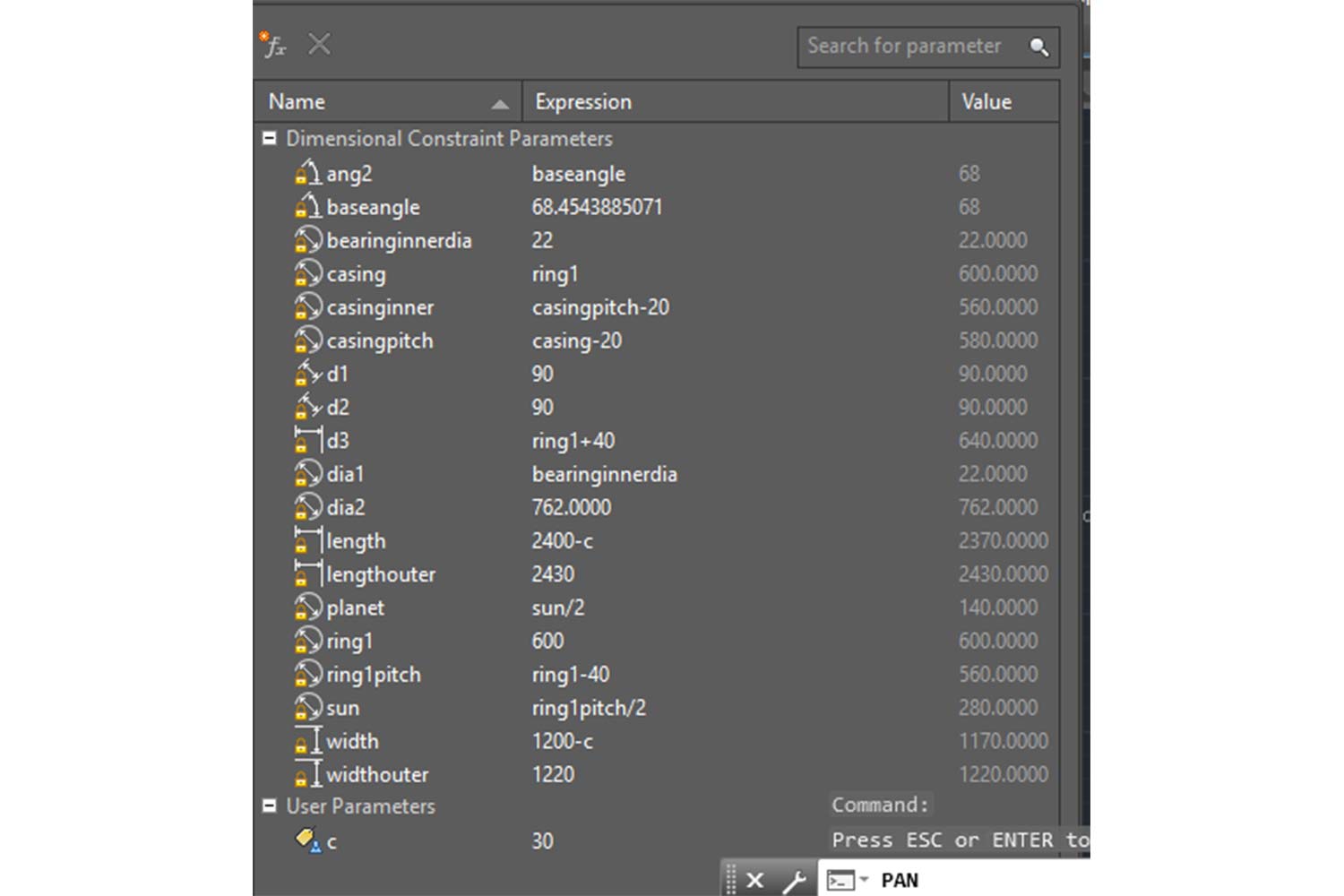
Parameters
Below are independent parameters
Outer Diameter of ring gear : ring1
Clearance : c. Clearance I gave from the original size is 30 mm from one size.
Width of the material sheet : widthouter
Length of the material sheet : lengthouter
parametric GIF
So as I decided both the frame and the planet gear assembly will change accordingly.
Deciding the inner diameter for Planet gears
So for planet gears, I have to decide the inner diameter, I have a bearing diameter(outer) of 47 mm so I have to check which inner diameter of the planet gear will be good. since I have to check for the holder also I did
some experiment cuts to know which dimensions will be good for assembly, since Dowels are tapers, I can't have an exact idea which dimension will work properly.
So I cut some and found the exact one, I generated a code file on partworks 3.5.
For now, I made some conclusions about inner diameters.
Inner diameter of Ring gear : 47.5 mm
Diameter for the Holders : 19.5 mm
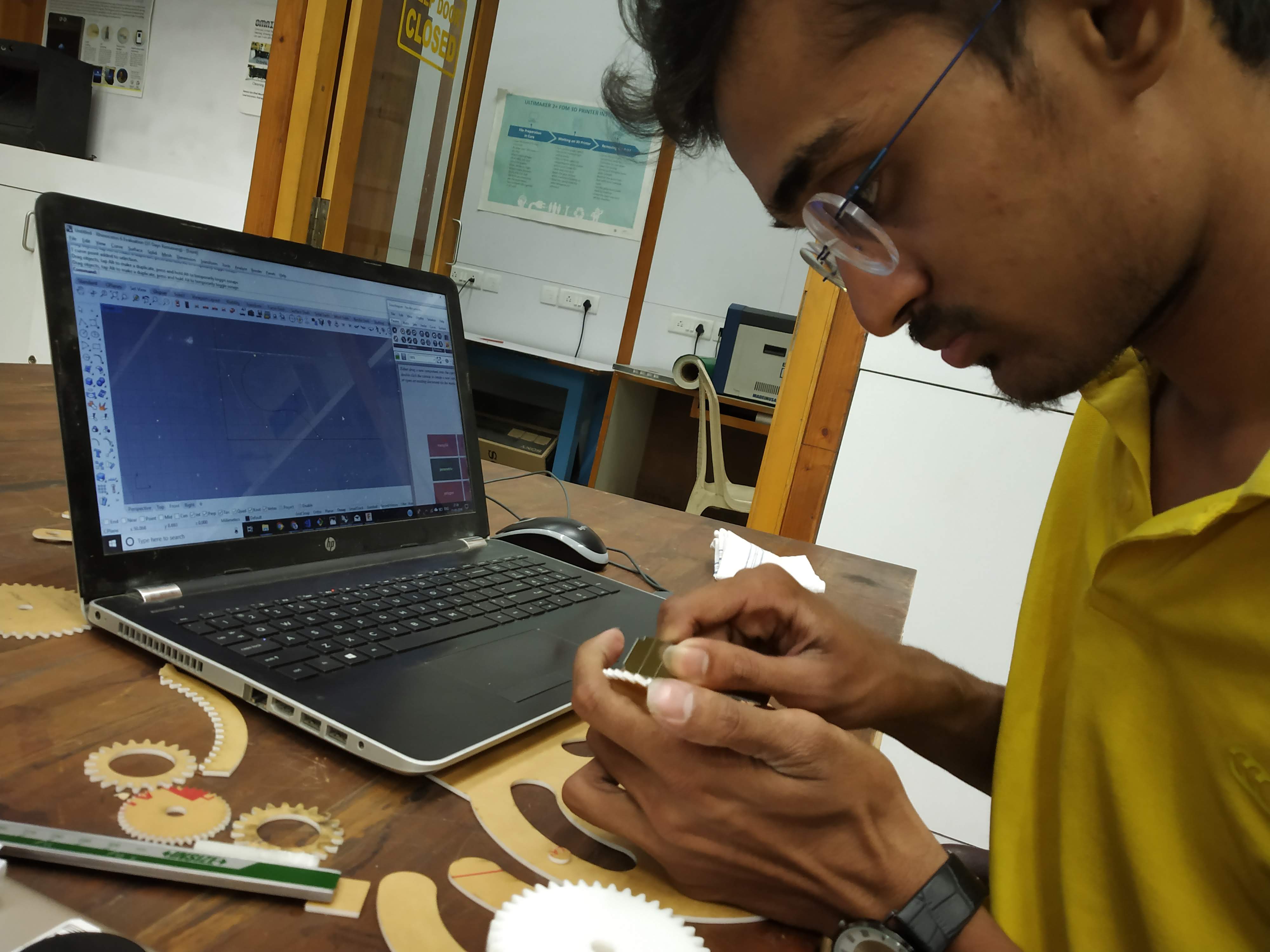
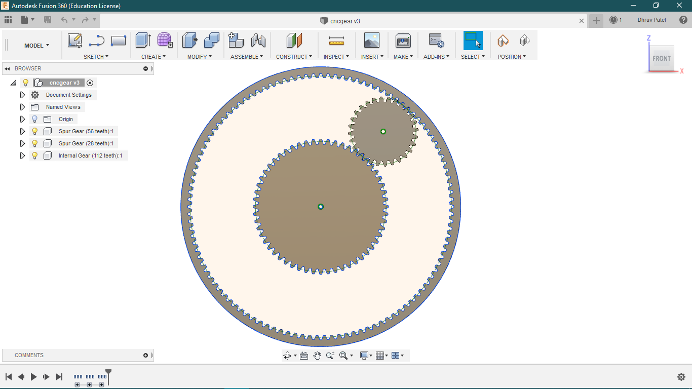
Design in Fusion-360
After knowing the pitch diameter I generated a gear profile on fusion-360. The process of generating the gear profile is the same as I mentioned above in prototyping. after generating profiles
and manual
check on the cad I generated DXF files for each type of gear.
Here I didn't generate the inner diameter of gears, that part I can do in Autodesk after generating .DXF files.
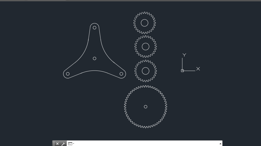
Back to autodesk
After then I arranged profiles according to the sheet. The reason I pit small holes around profiles is for screws, I noticed in CNC we spent much time in mounting the sheet and it is a tedious job, sometimes we need to
mount screws in between the sheets. but the main problem is screws can be in way of our toolpath and we never know exactly how far it is from the main tool path, I saw some screws are cut from the tool so far.
So the solution I came with is to use Pockets. I was going to cut Pockets in a sheet of 1 or 2 mm and place the screws there. so I can have a perfect location where can I put the screws and the main
advantage is if I have to change the location of the profile I will know where to put the new profile exactly.
One can Download the CNC bed file from the sidebar.
using Reusable sheets
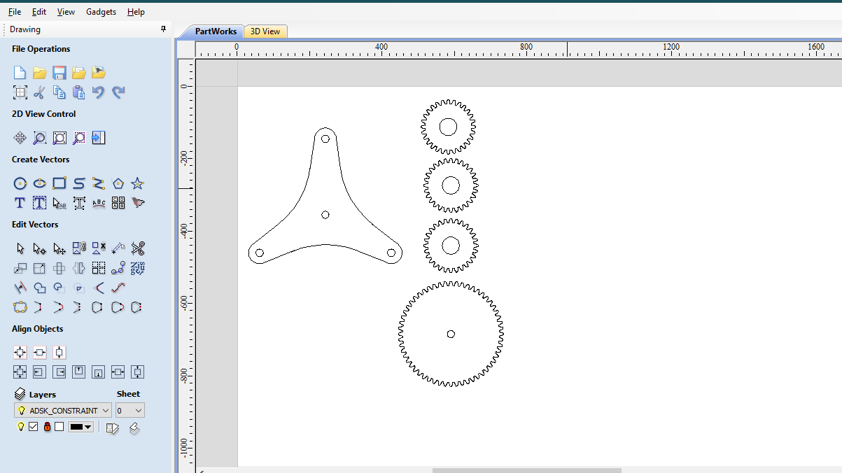
In the lab, I found we have one sheet which I can use for my sun, ring and axle and it will help me to know about cutting clearance, if I have to give the component the kerf or not. so I went
to cut these three profiles. after making these cutting files separate I went for a cut on CNC.
I uploaded files in .dxf 2004 version.
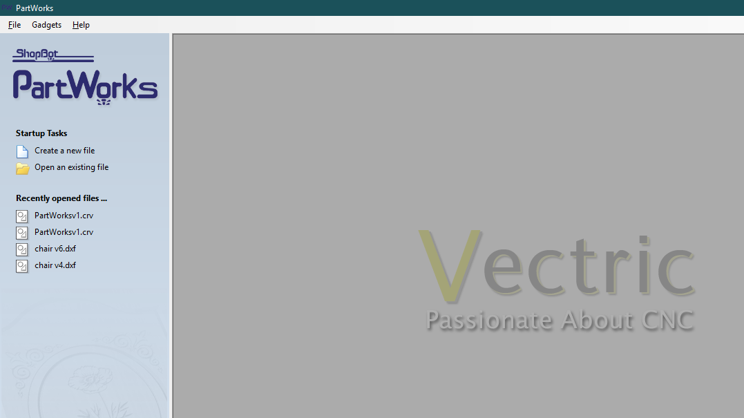
Partworks
Partworks is a software solution for cutting and creating different shapes in CNC. Partworks can help to generate 3d patterns with profiles, Pockets, Drills. with the
partworks-3D user can able to do 2.5D cut or 3D milling.
Click here to see 3d milling in Partworks 3D in Week 10. Click here to know more about partworks.
partworks
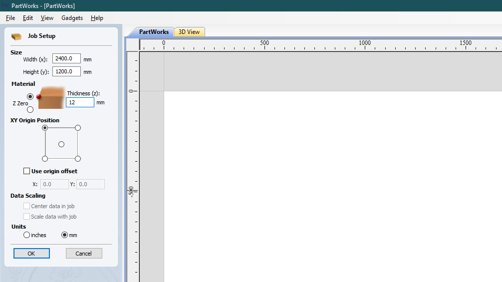
In part works before importing the sketch, we have to give Bad size - cutting sheet size. to do that click create a new file.
bad size
There is a small issue between our CNC and partworks software, they have a different orientation. Axis orientation differs by 90 degree anticlockwise.
In our CNC,
X axis - Width : 1200 mm
Y axis - Length : 2400 mm
But since axis orientation is different in CNC and the partworks I have to interchange the values of Width and Length because they are differ by 90 degrees anticlock.
In Partworks
X axis - Lenth : 2400 mm
Y axis - Width: 1200 mm
Material thickness : 12 mm
Units : mm , Units should be the same with the software you exported files, otherwise it will scale up or scale down according to mm and inch scale.
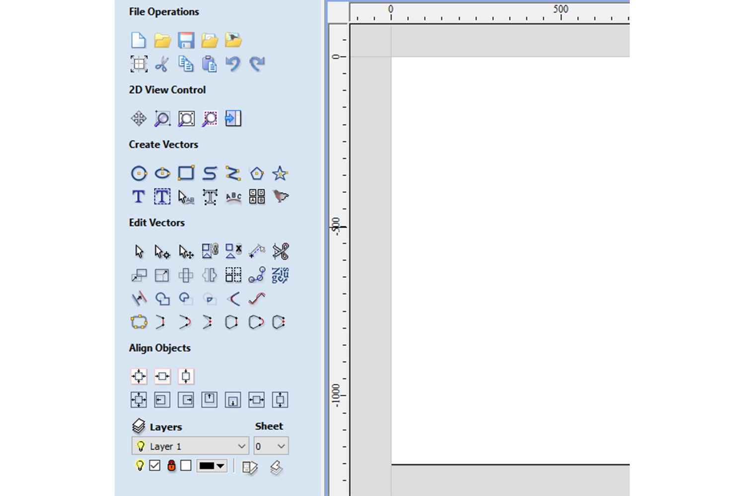
Tools
create vectors: for test cut on the CNC, one can directly create profiles for cut

Edit vectors :  It is used to modify the curves, the bottom part of the section is for joining curves, suppose curves are not joined, it will join the curves if a curve is not joined machine will cut that line and arc as an individual curve and it may cause problems.

Align objects : it will align objects

Layers : It can help to orient the design files and separate two types of different operations.
Import files to partworks
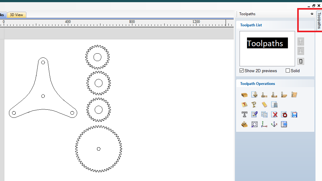
Toolpaths
Click on the Toolpath on the side to generate toolpath.
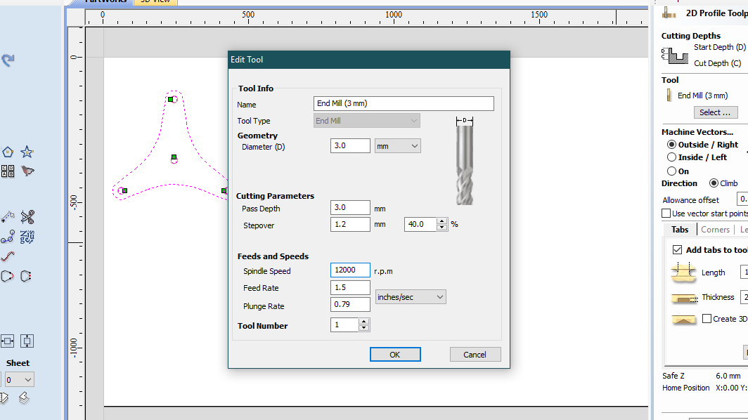
Select tool
I used a 3 mm endmill milling bit for cutting.
Pass Depth : Pass depth determines how many phases you want to cut the material.

If I Put directly 12 mm here, it will go straight 12 mm down. it is not advisable because the tool will face very high forces than, so I decided to give 3 mm passes. each time tool will go 3 mm down after completing one cutting cycle and my material will be cut in 4 phases (12/3).

Spindle speed: it determines the RPM of the Spindle.

Feed rate: it determines the Feeding Force applied to the material.

Plunge Rate: Plunge rate is the speed at which the router bit is driven down into the material when starting a cut. if is too High it will break the tool or make a crack on the surface of the material.
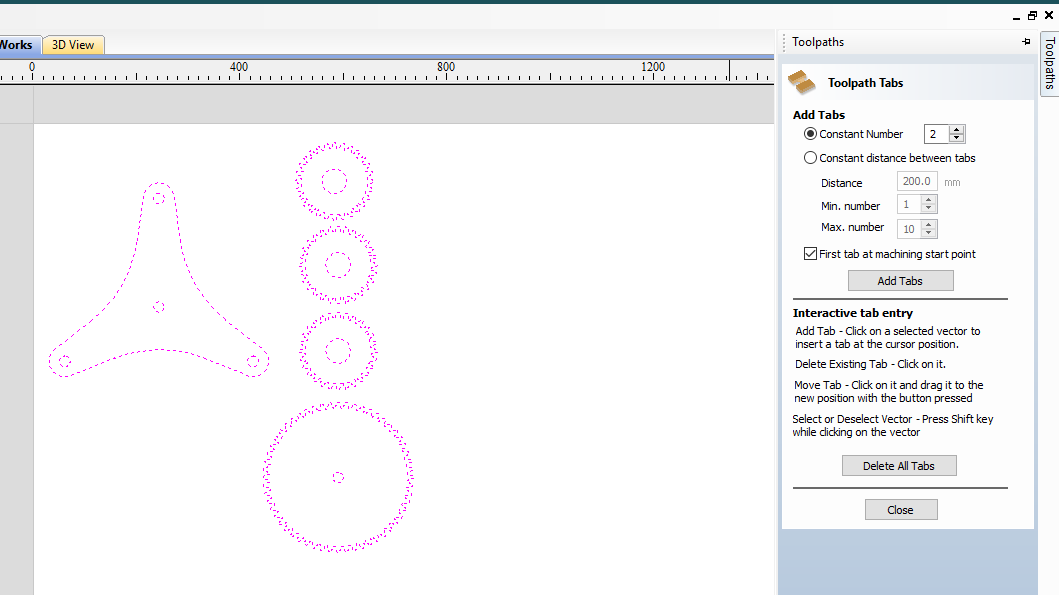
Tabs
Tabs will hold the material on shit while cutting.
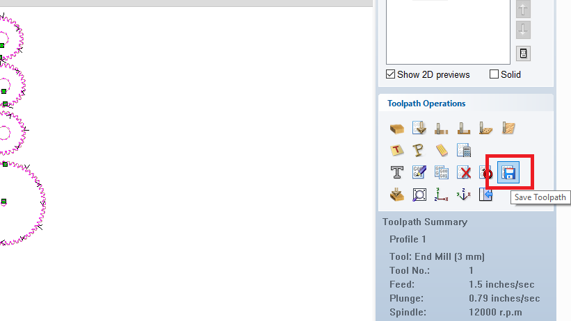
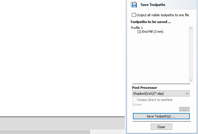
SAVE toolpath
I SAVE THIS FILE ON Shopbot (Inch) format.
On Shopbot software - spindle routine
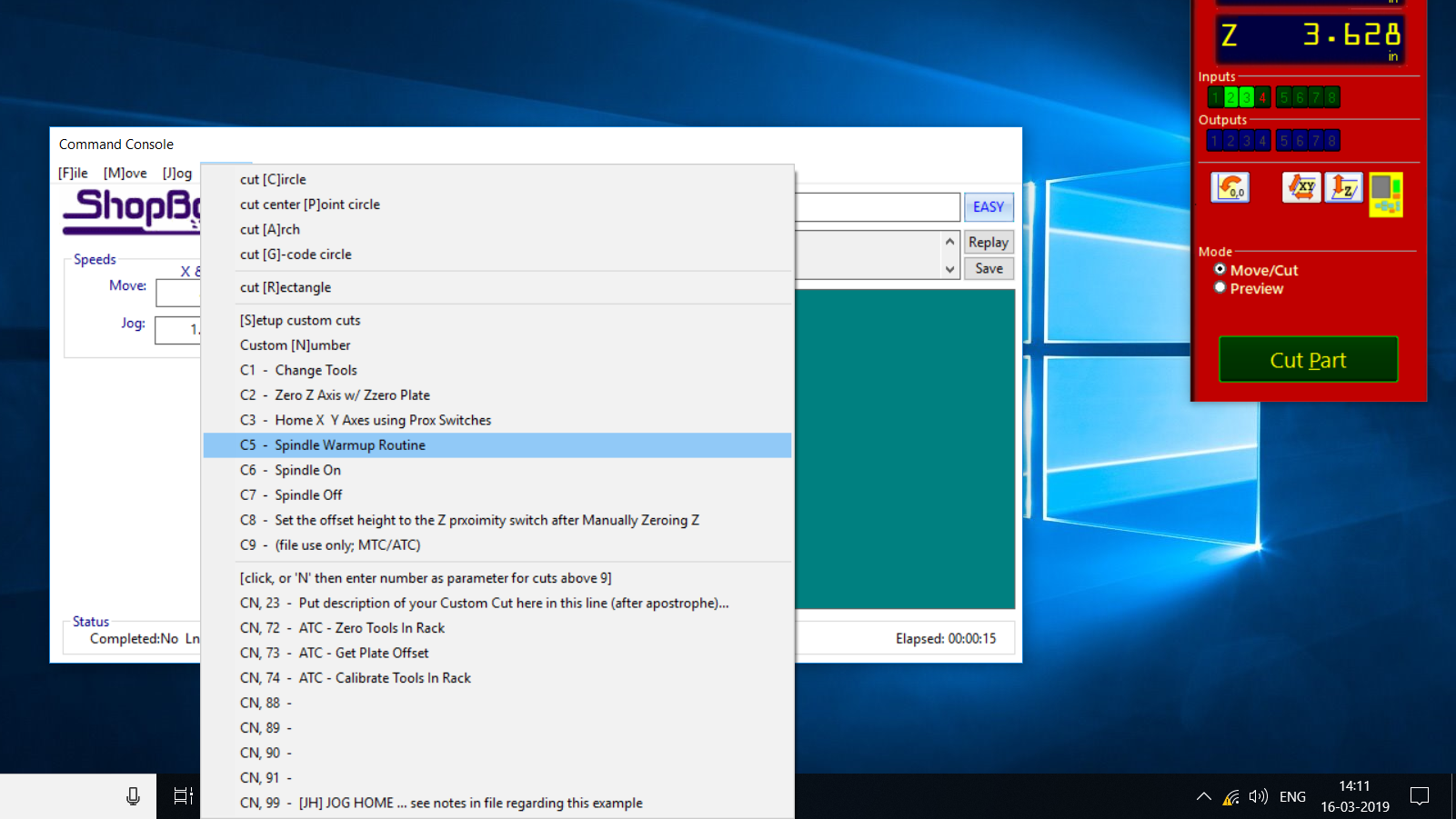
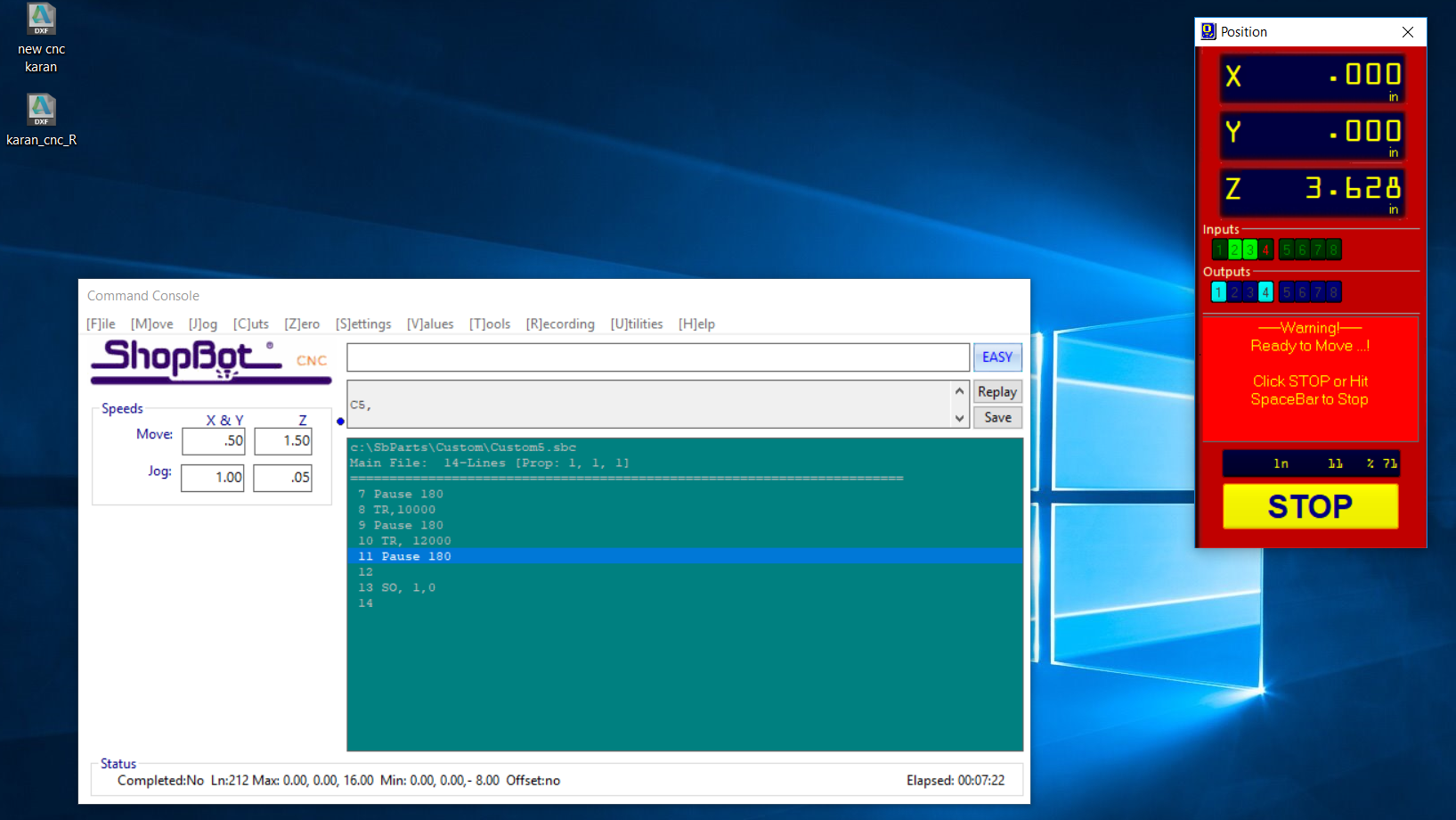
After generating the Toolpath now its time for cutting operation. After opening the SHopbot it is good practice to level up the machine for a while and Run the Spindle worm up command. it will Re-circulate
the oil
on the Spindle assembly.
Then Import Tool path file.
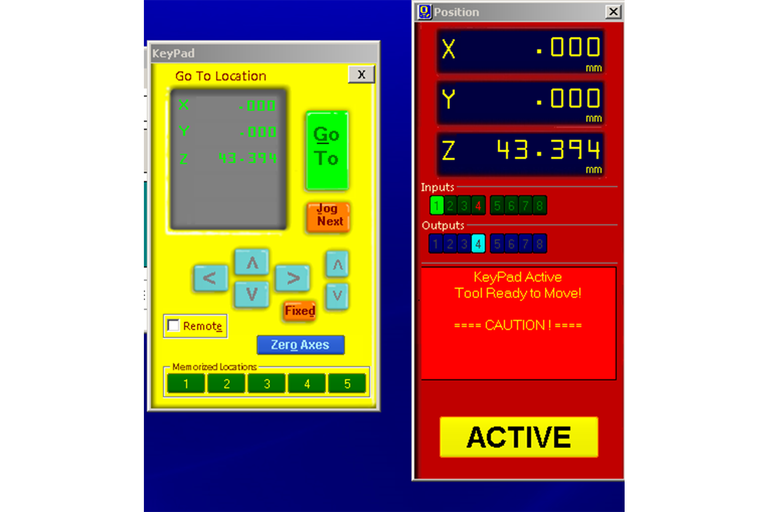
Keypad
On the Control box, there is a Keypad box which can be used to move the spindle in 3 axis to set up origin. After setting up the origin click the zero axis button to make that point origin.
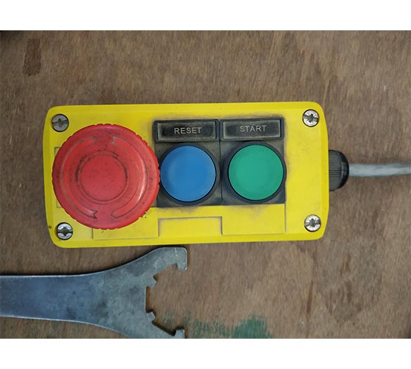
Emergency Switch
- Emergecy Switch (Red push button) : To stop the machine immediately
- Reset Switch : To reset the CNC code to ensure there is no previous running G-code and machine is good for new toolpath.
- Start Switch : to start the cutting operation on CNC.
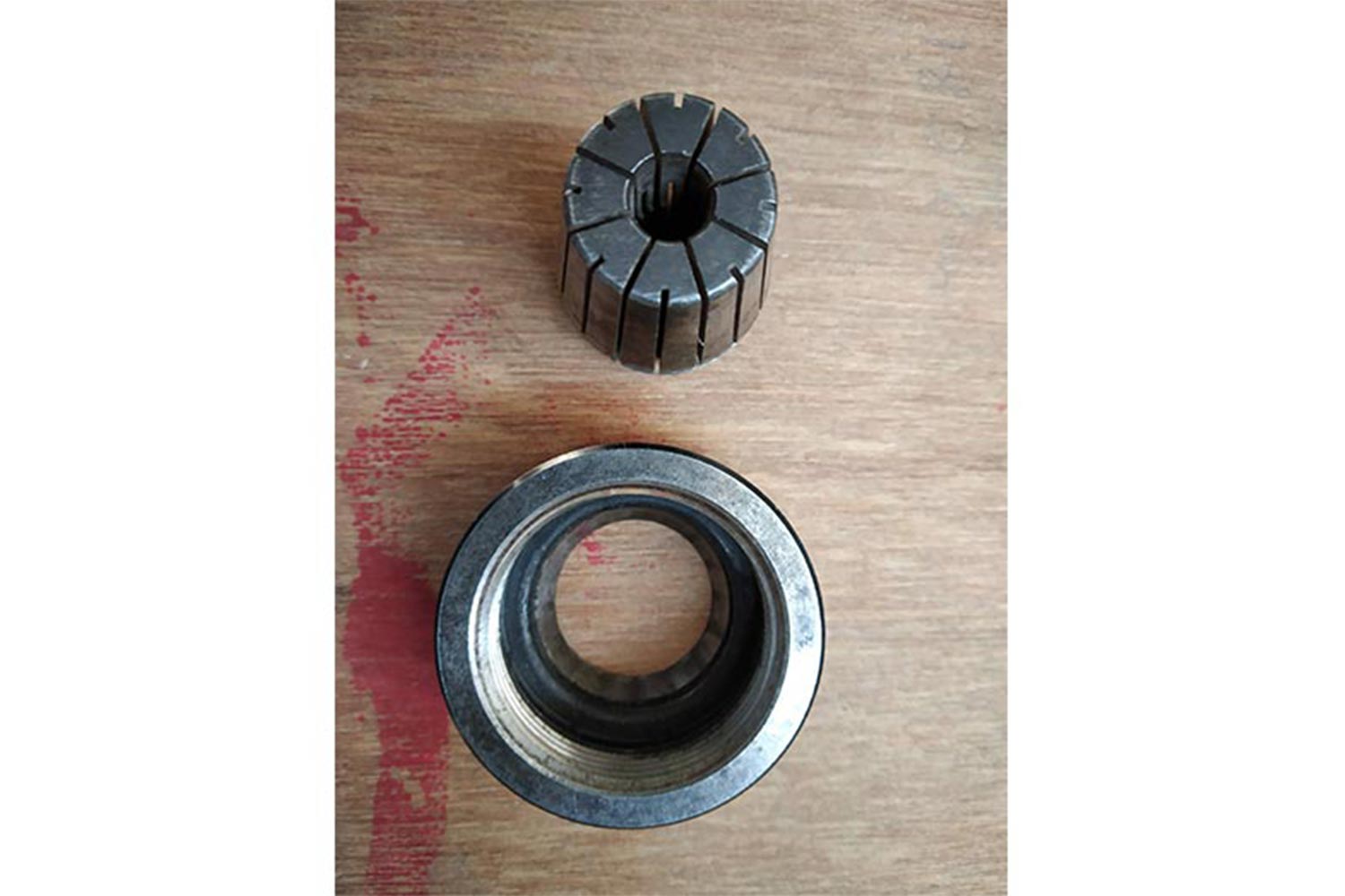
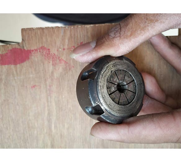
Setting up Milling Bit
Setting up the 3 mm bit on the Spindle. First Chuck is fixed on collet then collet is mounted on the spindle. After that bit is inserted on the chuck and tightened.
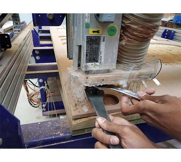
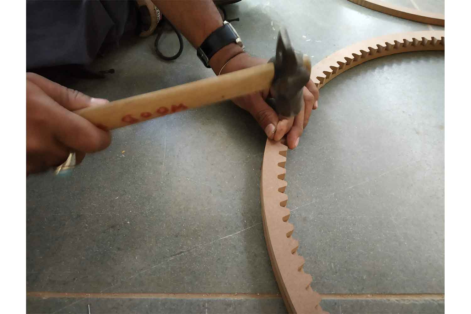
Cutting
Post processing
So accidentally I gave Tabs on teeth profile, and in some gear cut depth was not enough so I have to do some post process.
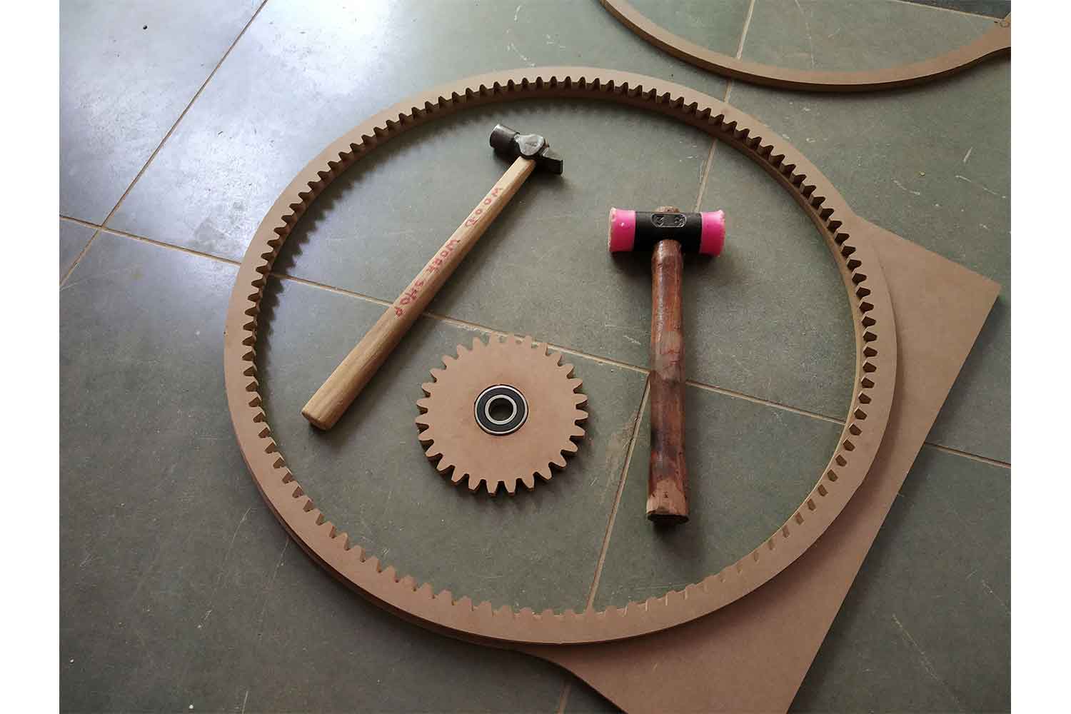
fixing Bearings
Now it was time to check the inner diameter again, and it was perfect Bearing fit perfectly
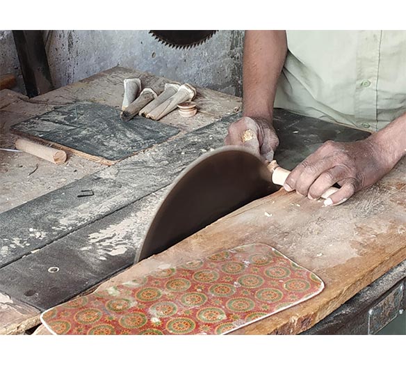
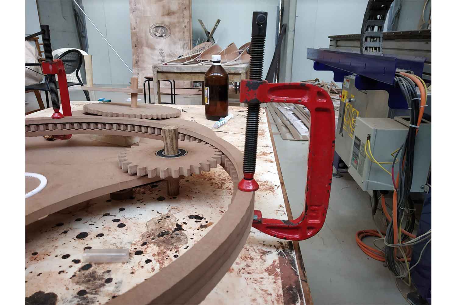
Axle
Assembley
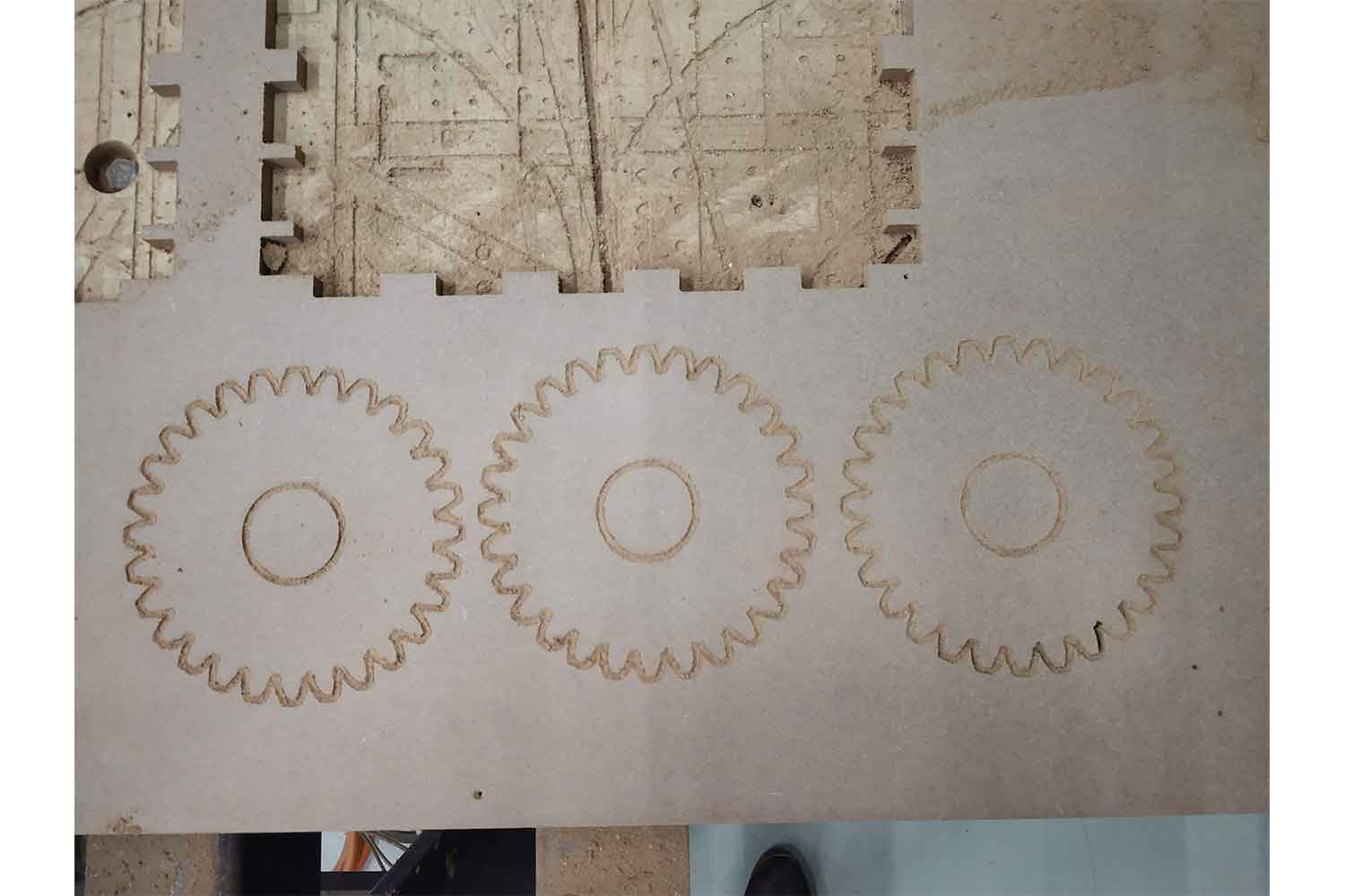
Before going for outer ring gear I want to check manually if I Need to give more clearance to teeth or not, I had to take many iterations in the Laser prototype that's why I wanted to be sure. for that tab error, I cut more 3 gear so I can have better motion.
Ring Gear making
After checking that tolerance is good enough I went for cut ring gears and frames.
Toolpath making procedure is the same but this time I tried a 6 mm drilling bit. I want to try it for increasing cutting speed.
Feed rate : 1.5 inch / s
RPM: 14000 rpmAnd I messed up!
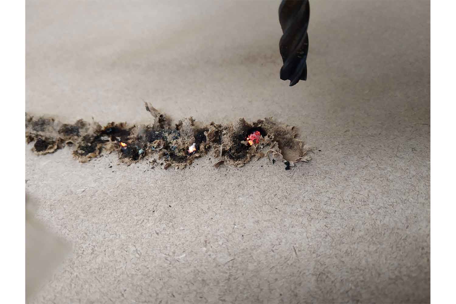
2 flute spiral bit
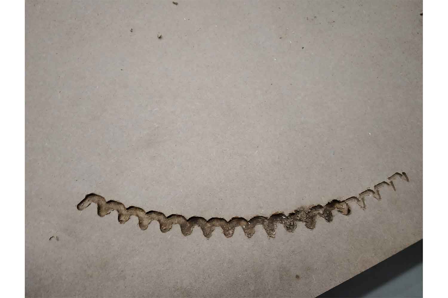
I thought this is because of speed so I reduced it but no help from that, I think the tool diameter is too much for the teeth profile and that's what it burning the sheet by slowing down at edges. Then I tried 2 flute spiral bit
3 mm
bit.
After that, I reduce the feed rate to 4.5 inch /sec and it was perfect!
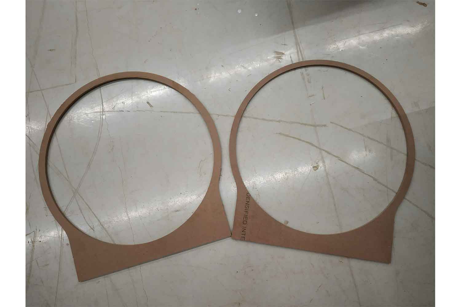
Frames
These are my frames for ring gear which will hold the ring gear in assembly. I gave an I mm pocket in the inner diameter of the frame so planet gears can rotate freely.
Ready to assemble
Starting from Frames
I had different options in Fabrications
Could use Buiscuit joinery by making slots in frame
Use of glue for permanent fix
Use of Nails for Fast assembly and disassembly
Using biscuit type joinery: it would be good if I could use Biscuit type joinery and I intended to do that, but two frames should be concentric for that if not they will misalign and I will not able to fit my planetary assembly. I needed something which is good to change the joints position if frames can't align.
Using Glue: Glue would be a permanent solution, if I kept little bit misalignment it cants be fixable.
Use of nails: for my case, it was a solution, I could realign if there's some error in misalignment, it is easy to add and remove also. ao I choose nails.
Fixing secong Frame
Using araldite glue
Since friction force was not sufficient enough to move the sun gears, so I used Araldite glue.
FUll assembly
First try full assembly
Oops !!! Sun gear is not able to hold its place in a vertical position, it was my design fault I think, I should have to take care of back support in sun gears, I tried it on the Horizontal position Anyway.
Sub assembly working
I was very happy it was quite smooth but I don't know where it is h=giving problems! even the sub-assembly of planet gear and ring gear was quite smooth but when I integrate them it became too tight to rotate and sun gear can t handle that thrust for a long time. But it was rotating though, below is the video.
Full assembly Second try
But I enjoyed it from the start to the end! The end results were not as quiet as expected though but it helped me to develop some maker skills to use different tools and though how you can do things step by step! At this movement, Our
Two
instructers and the whole team were helping me to make this thing work for me! It was a very good experience, appreciated !
Group work
In computer cutting group work we as a group was going to try a different speed and feed rate on MDF and Plywood so we can have a conclusion in which speed and feed are giving better surface finish.
my role was to handle the machining process in group work, I and Samiul were trying different speeds and feed on the materials and checking cutting behaviors! Click here to redirect on the group Website.
conclusion
As I mentioned above CNC week was amazing from start to end. it gave me a feeling of being a maker which was one of the main reasons I wanted to Do fab academy!
In CNC week I learned much more about laser cutting moving assembly, Partworks software, Shopbot and very much new to me how to assemble things. The last was not
perfect though. Still, a week was great!