Week 4 : Assignment
- Cut something on the vinylcutter design, lasercut and
- Document a parametric press-fit construction kit, accounting for the lasercutter kerf, which can be assembled in multiple ways and
In week 4 we are introduced to computer controlled-cutting. In computer controlled-cutting, we use computers to do fabrication processes. Instructions are given by codes of the line which can be
generated manually or we can turn the geometries into codes.
code which is used in machine for fabrication processes called "G-Code". G-Code is a numerically controlled programming language used in computer-aided manufacturing to
control the automated machines.
example of vinyl cutting - link
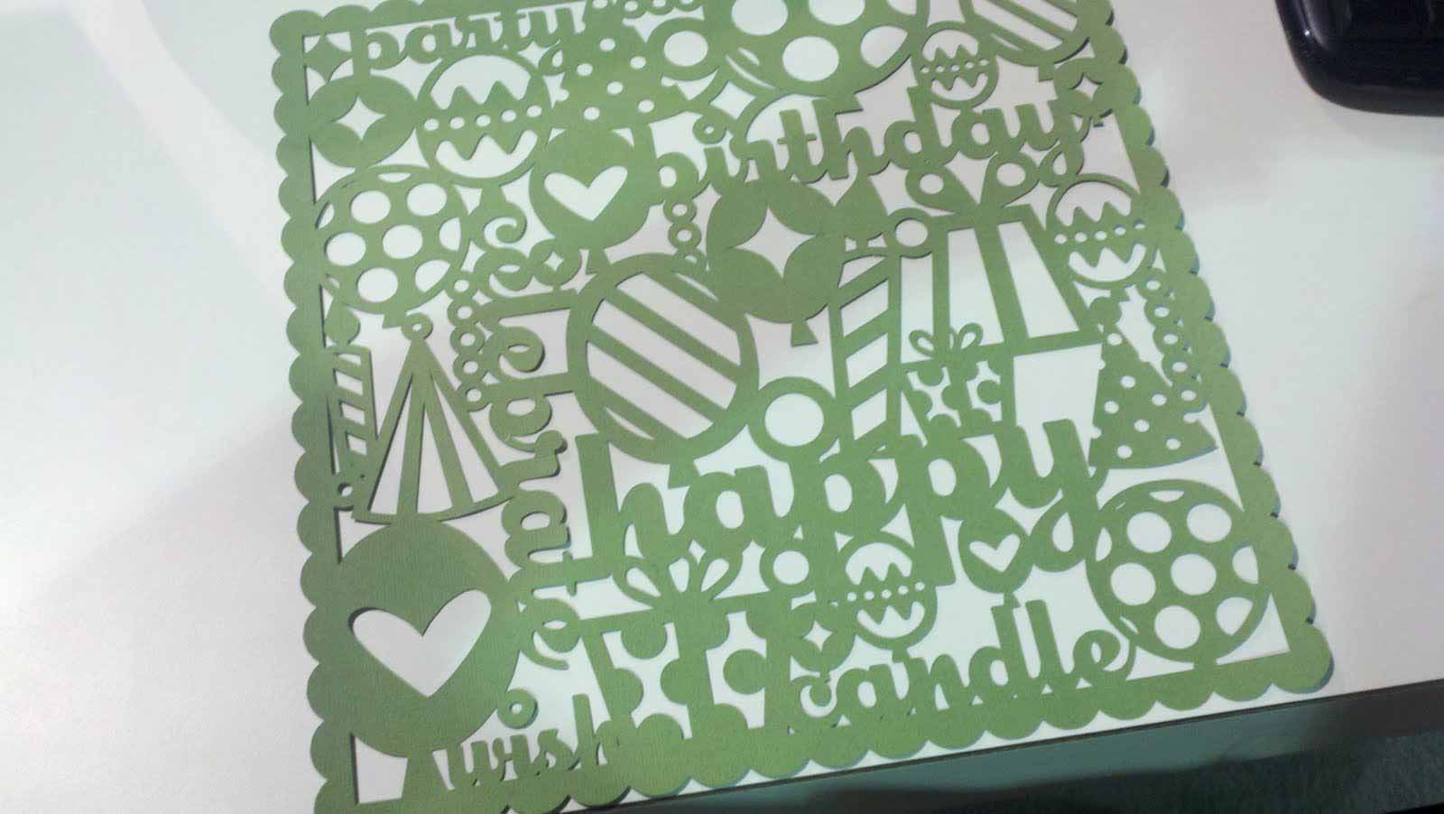
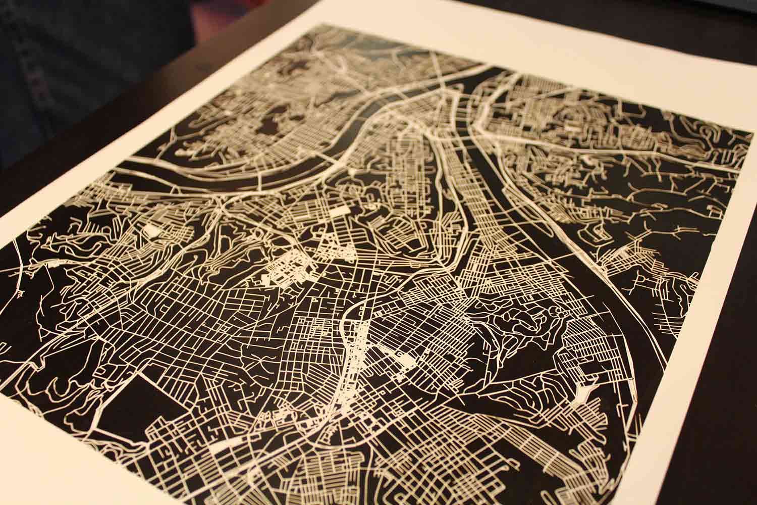
Road map of city - link
In this week I learn:
- Vinyl cutting- how to use Roland vinyl cutter
- Laser cutting- SIL laser cutter
- Rhino with grasshopper
- RD-WORKS laser cutting softwere
- Cut studio For vinyl cutting
vinyl cutting
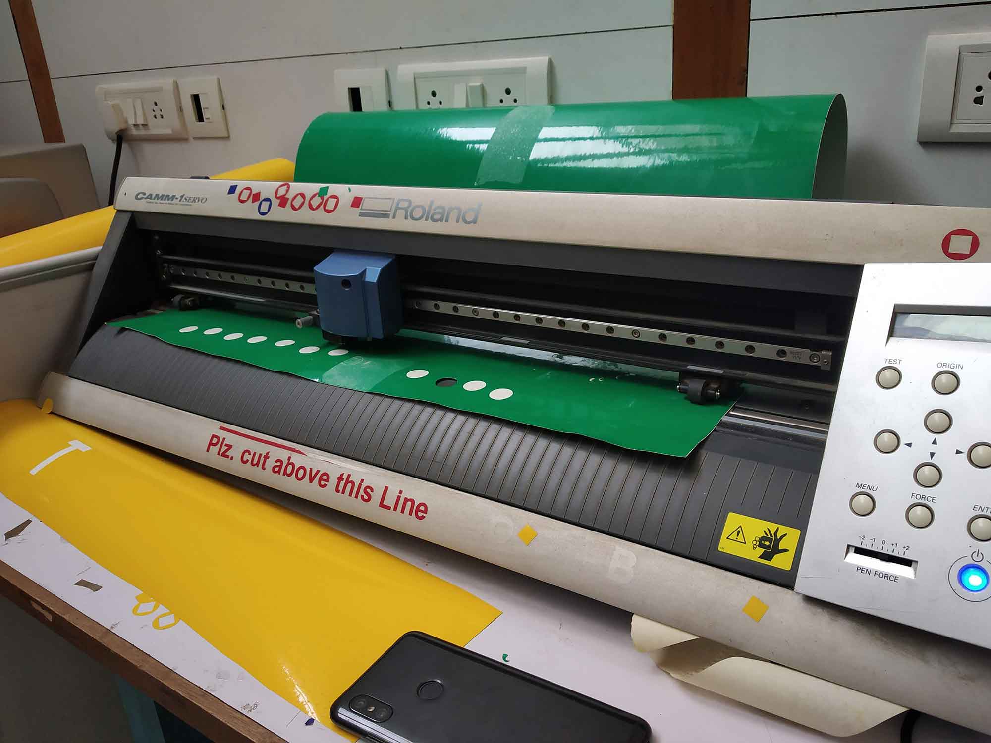
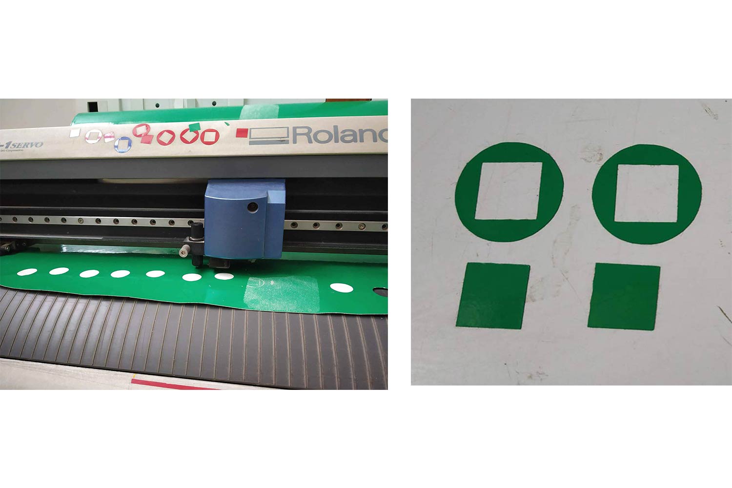
Machine : Roland GX24
A vinyl cutter is a type of computer-controlled machine. Small vinyl cutters look like a desktop printer. Like a printer controls a nozzle, the computer controls the movement of a sharp blade over the surface of the material. This blade
is used to cut out shapes and letters from sheets of thin self-adhesive plastic (vinyl). The vinyl can then be stuck to a variety of surfaces depending on
the adhesive and type of material.
To cut out a design a vector-based image must be created in a software program (usually Adobe Illustrator or Corel
Draw).
It is then sent to the cutter (Click Hear) where it cuts along the vector paths laid out in the design. The cutter is capable of moving the blade on an X and Y axis over
the material, cutting it into any shape we can design but there will be always one perfect setting for each design depends on the geometry. Since the vinyl material comes in long rolls, projects with significant length like banners or
billboards can be easily cut as well.
To know more about vinyl cutter you can Click here.
Controller of vinyl cutter
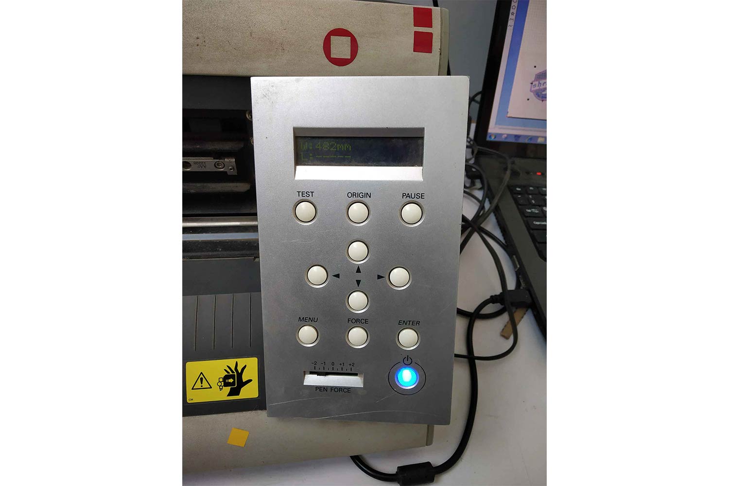
TEST : for testing the material or fixing the parameters like

ORIGIN : To set the origin of the machine

PAUSE : to pause the machine while running

POSITION CONTROLLERS : for positioning material and blade

FORCE : to enter the machine force

PEN FORCE : to give manual force while cutting operations (Increment / decrement)

ENTER : to select the required settings
Doing test cuts
First of all, we go for a test so we can know the cut abilities of the vinyl cutter. I used GSM - 20 material here, In Test cut, we found out at which speed and force Inner square can be removed from circle smoothly. For test cut I found Force = 150 gf and speed Speed = 20
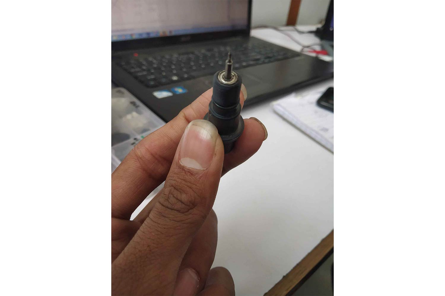
Change the blade
There was an issue we were finding in cuts they were not as smooth as we imagined, so we try another blade and it was quite good.
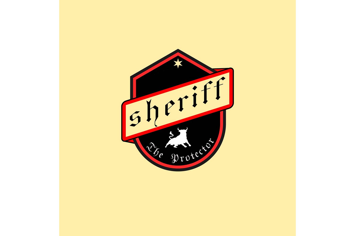
Logo making vinyl cutter
I decided to try my Sherrif logo which I made in Week 3 in INKSCAPE softwere. it has good deatils in the fonts I can also able to know what will be my design limitations in logo making,
Download files from here inkscape(.svg) , inkscape(.jpg), inkscape(.eps) .
Cut STUDIO softwere
I tried both Vector and Raster formats for logo making. I wanted to see the advantages of these two formats in machine operations. Cut studio can work on both vector and raster formats. you can import raster images of extensions (.bmp, .jpg, .gif, .tif, .psd) or vector images of (.EPS or .ai).
Raster Image
First ai went for raster image, raster image can be downloaded from Here . As I say which vector formats you need to upload on the cut studio, Uploading Raster formats are easy you can just import it without any pre Processing.
cut studio interface
This is a cut studio interface, it is quite simple and easy to understand, you can import images from file menu here. here in default state Origin will be in bottom-left.

Import jpg format
Only one limitation in raster formates is we can choose our cut paths directly we have to do some or cant generate all the desired path lines, we need to do some work on that by creating an image outline to generate the best paths we can.
(let's
understand this later). After importing the jpg image or any raster format (JPG in my case) you can just Right-click on the image and select Image outline. first, disable the image view.
What we are doing here is we are setting different contrast of images to create different path lines, these paths are going to be used by cutters. in the dark part, the software will target the more dense colors and in light parts, it
will target bright ones. I have to select in between to generate a tool path of the image.
Set origin
After setting the outline we have to set the origin of the machine, what we can do here that one can set the cutter ate the desired position and set that point as origin by clicking the origin button on the machine, that time origin for the
machine will be set. but we have to tell the software what is the cutting area.
For setting the cutting area we need to go Cutting > Properties and select GET FROM MACHINE.

Changing speed
In Roland-GX24 speed is 20 cm/s in default. it is the maximum speed of the machine, for my job it was Too high, letters can tear off during the cutting process. so I decided to keep it to 1 cm/s first.The force was 150 gf.
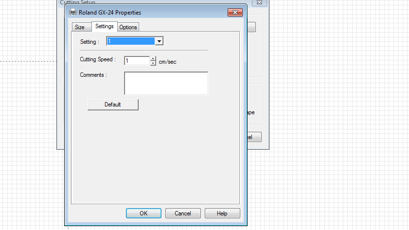
reducing the force
It was cutting Bad. Force was too high for cutting the material, so I decided to change it to the 110 gf.

Final Video
tools to know :- Image outline- This tool will scan the image and generate outline of image border
- Cutting- Cutting is used to set the origin point(from which machine can start cutting) of machine
Post Processing
After doing the vinyl cutting on material, it is time to make a logo out of it. It is a little sensitive process it needs to be done with proper way otherwise logo will take bad shape and will not be good to put on somewhere(Main objective)
Use of transfer tape
A Transfer tap is used to place the logo on the place where you want it to.
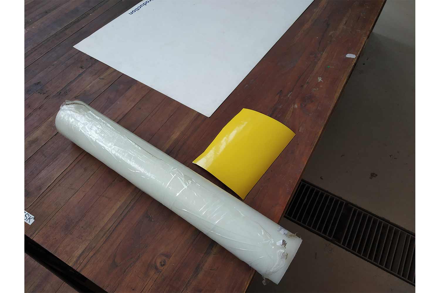
Cutting out transfer tap
First I cut the transfer tap I needed from a roll and place it on the part since our small roll of transfer was finished I have to take out bigger one and I cut one portion of it to place transfer tap on cut part.

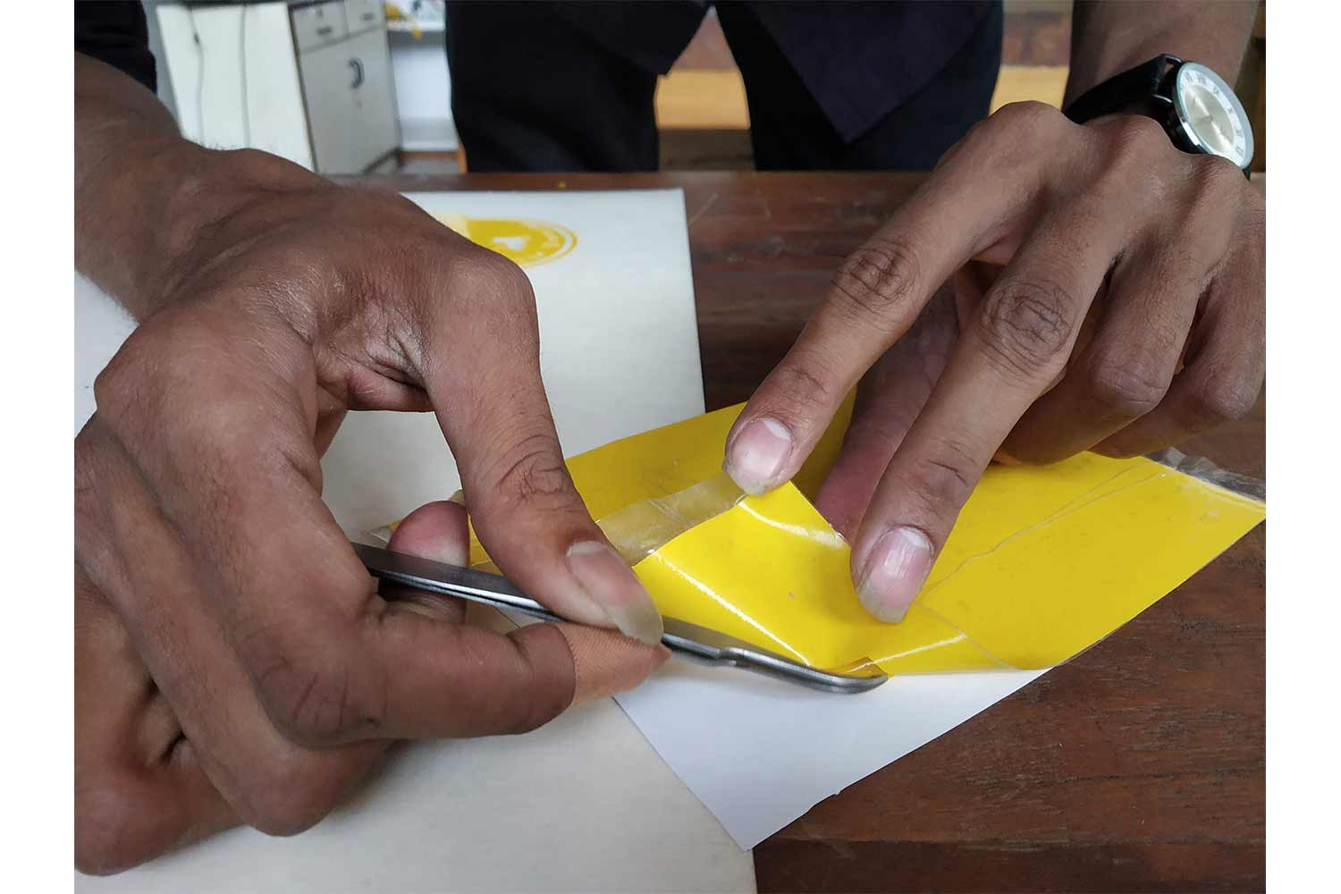
Pulling out unnecessary material
I removed unnecessary material first! For easy removal one should try to pull transfer tape parallel to the surface, in this case, shear will help to remove the material, directly pulling it up may brake the material and it will one have to make the logo once again.

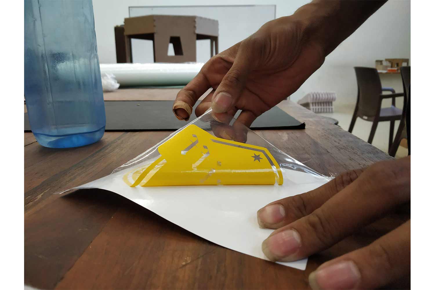
Using transfer tape one more time
Then I took out another transfer tap and removed my logo from a roll and place it where I wanted to.
What one can do here is put the logo one the roll( its negative side ) if you don't want to stick that on the instance and take it out when you need to, it helps when you have more than one logo to place.
I put it on my laptop.
 ,
,
With vector format
Then I did the same process with vector format, I used .eps format for it. The difference between this type of format I explained above, but vector formats are very good when you need perfect
cutting paths, it will cover all the vector lines in cut paths, but for that one will need vector formats, so I used .svg format, The original file of Inkscape. Click here to download.
In vector format the cutting process is very simple, you don't have to make contrast changes to generate a path, the tool path will be there initially, but the more complex thing is converting or preparing the image for the Cut
studio software. the procedure is little complex and needs to follow some certain ground rules, I will not say the method is not general but we need to use that for our cut studio version.
.eps format
As I wrote cut studio can run on .eps and .Ai formats. I tried with .eps format. I used Inkscape and illustrator to generate a .eps format.
Convert text into paths
It is good practice to convert text manually on paths. for doing that in inscape go to Path > Dynamic offset and select text.

Inkscape
You cant use export option in Inkscape to generate eps format, so go to save as and export the .eps file from there. you will find the option to upload in Postscript version, I checked both looked the same on eps format. But I recommend you to go for a lower version, in case you have an old system.
Click here to download file.
export from Illustrator
I exported with illustrator, I will show why I have to do it. but understand the process. in illustrator, one has to export in illustrator 8 EPS(for our cut studio version). Click here to download the file.


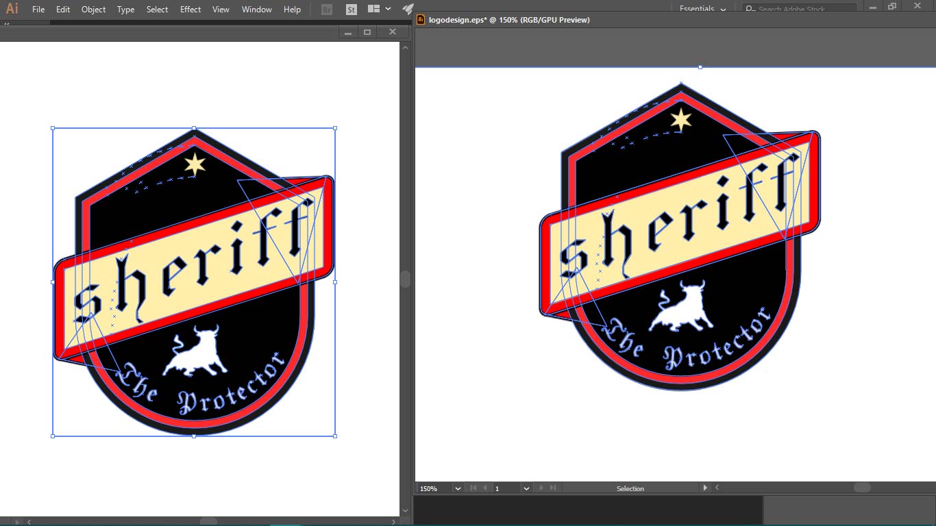
visual comperisson
The below image is a comparison of the eps file of Inkscape and illustrator. both look the same, both have same path lines generated but the problem is when you import it in cut-studio, for Inkscape file when you add the file on the software it will not show up, but illustrator file works well. that's why I have to choose an illustrator for Uploading.
imported on cutstudio
As I said toolpath will be generated initially and no additional process require to it, but one thing is to take care of is to remove unwanted paths, sometimes in vector, there are some path line remained while designing. These will mess your logo in the cut if you don't eliminate them.


Post processes
post-processes are the same in vector format as I mention on the raster but one advantage is that you will have more options about removing unnecessary material since each vector path is going to cut. below is an image of the vector cut logo.
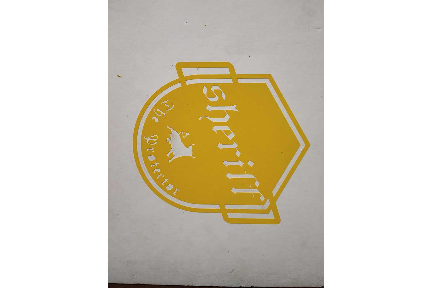
comperisson
Here the left one is Raster and Vector. I had better options to change font locations in vector. I could direct the toolpath more efficiently, but it is not good if you have a more complex logo, I generally
observe, if some path is going through design it will cut through it and it can lead to bad position while removing the logo and unwanted material.
For high contrast one can go for the raster type, it is also good for complex designs as far as software can detect edges properly.

Laser cutting
In Laser cutting, we are assigned to make one One press-fitting model using the concept of Parametric modeling.
Parametric modeling
Parametric design is a process based on algorithmic thinking that enables the expression of parameters and rules that, together, define, encode, and clarify the relationship between design intent and design response.
Parametric design is a paradigm in design where the relationship between elements is used to manipulate and inform the design of complex geometries and structures.
The term parametric originates from mathematics (parametric equation) and refers to the use of certain parameters or variables that can be edited to manipulate or alter the result of an equation or system.
In conclusion Parametric design helps the designer to modify the design very efficiently, in simple words I take one dimension and take it as the main parameter which affects other parameters directly or indirectly, I will try
to relate it
with other dimensions as a set of the equation, which I already have to follow in simple modeling also, this set of equation will help to redesign the model quickly, if I change one parameter, all dimensions related to it will change,
in the complex design, there can be more than one parameter which is main or call it dominant in design.
in Maths dominant parameters can be called Independent parameter and other parameters as Dependent parameters, because their values depend on other parameters.
How it works ?
I prepared some basic models of parametric modeling to understand how I can use it in properly, I initially used Constrains to have relations between vertices, these constrain don't follow any expression, they follow simple
geometric rules.
List is below
Skecth with constrains
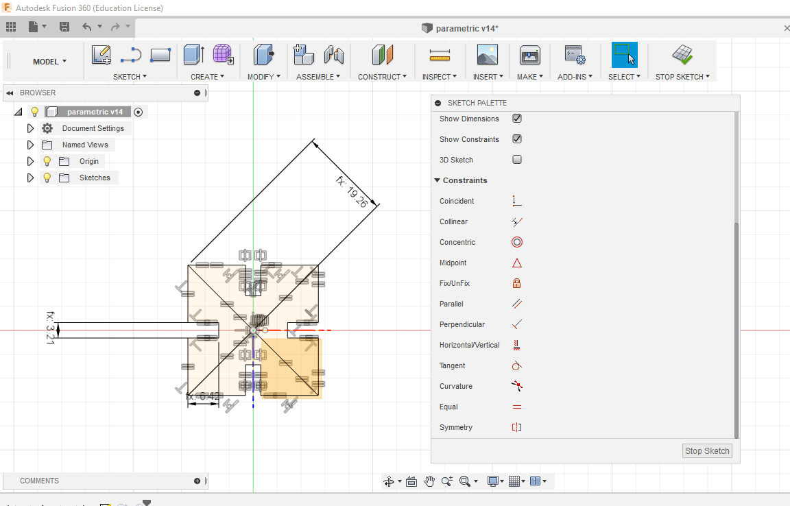
Below is a simple sketch I prepared and I used constrains like equal, perpendicular, parallel, horizontal, Symmetric. in this design, I have to think which parameter I should choose to be dominant because I have work-related
to press-fittings. I chose slot thickness as the main parameters because the thickness of the material varies and you may have to work on multiple materials in press-fittings, so here only slot thickness is dominant, and I
relate it which other parameters.
Parameters
In Modify menu click parameters to give the names of the dimensions, these names will represent the dimensions and it will be easy to work with names. Below is the image of my list of parameters, I choose thickness as the dominant one and it is related to the other one.

Other sketches relation
Here is the relation of thickness to other sketches, I used diagonal because it can control both sides of the square. no need to give every side relation. here Slot dimension is not used in the design, I gave it when I was figuring out whole parametric relation.

relations in sketch
You can put relations directly on the sketch plane. see below images, just define your dominant dimension(mine thickness) first, like Thickness = 3.21mm and then give relations like below.


feasibility in design chnages
The gif shows feasibility in design changes in parametric modeling.

trying another shapes
Then I tried different shapes. these designs are not for press-fitting, the only purpose was to understand the process.
Laser cutting format
Then I uploaded files for laser cutting. In Fusion-360, one needs to create .dxf file for laser cut. for that Right Click on the sketch of geometry and select save as .dxf format. Our laser cutter(SIL) was
working on the works and it demands to have .dxf files of version 2004. details about rd-works software are included in the Rhino section.
In case Fusion-360(.DXF) file is not importing in Rd-works, open it on AutoCAD and export again as version 2004 in DXF.
In AUTODESK
Then I opened the Autodesk command to delete the overlay using overkill command it is needed because if some lines are overlayed laser will cut twice that part and may remove unwanted material there.
OUTPUT
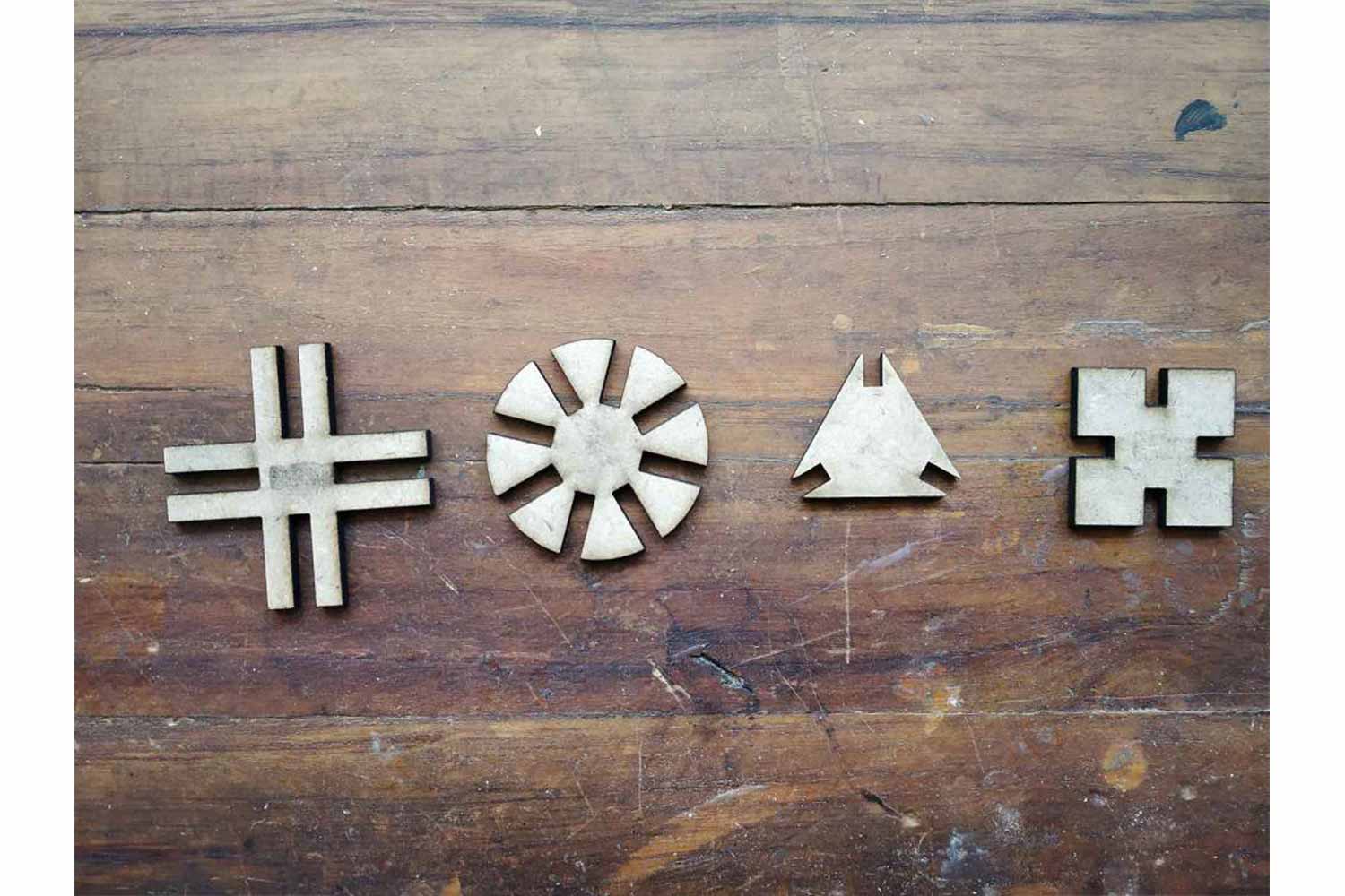
It was my first laser cut and it very pleasing to see these different shapes.Get file from Here Fusion file(.f3d)
Press fitting
Press fitting is joining of the two parts without any fasteners and glue, but only friction will be there. friction will help the modules to be connected. you can know more about press-fitting in Fab academy-tutorials. they explained the whole process of press-fitting.
KERFING
For press-fit cutting, I have to make one comb for measuring kerfing. kerfing is the removal of material by the laser in process,
so it will be always dimension difference in the parts you want to join from the original one. for component the removal of the Material, one may have to add or subtract dimension from the original one on cad.
To measure kerf of the material
Comb test
To know which dimension is good for the material Comb test is necessary. In comb test original dimension may Increment in some fraction (i.e., make some at w-.002″, w-.001″, w+.001″, w+.002″, etc. w is an original dimension) Use kerf
value
on increment/decrement. and after cutting you can test each slot by fitting in each one. Try to figure out which dimension is good to apply to the design and select it.
In my case, I was working on the material which thickness is 3.25 mm - MDF
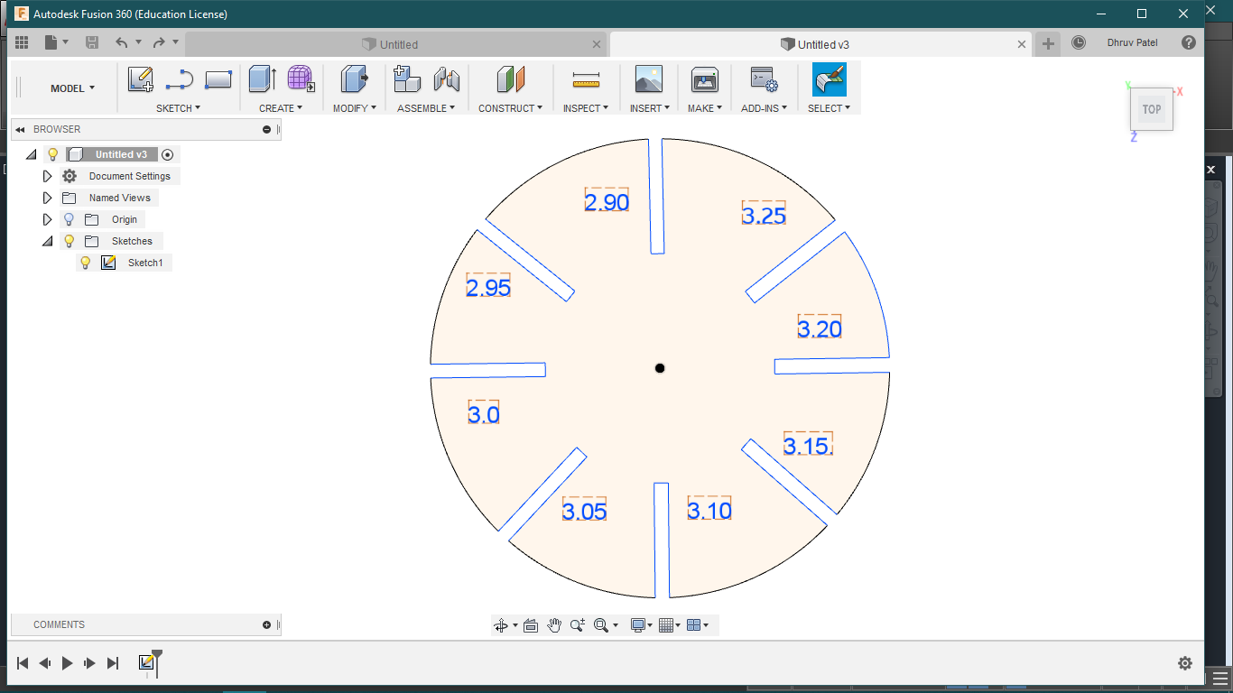
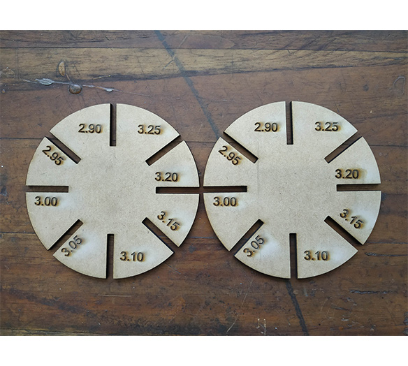
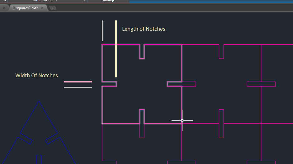
Design of comb wheel
you can see in the picture I have given various thickness's the comb slots to find out which one fits better, usually for female slots always less thick then original dimensions and male slots are thicker than the original one. You can download files from here.
3.25 mm comb test
Since my material thickness is 3.25 mm. I am preparing the file accordingly.
Generate DXF file from fusion.
To generate Dxf format from the fusion-360 Right-click on the sketch and click Save as Dxf format.

modification in autocad
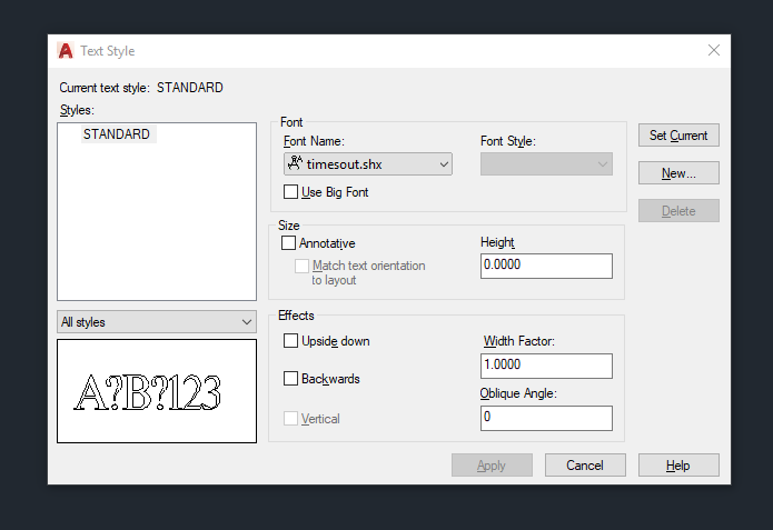
As I mentioned in the trials section, directly generated files from fusion-360 may not work, because of DXFs version issues. I lost my text I exporting the file, so I have to do some modification.

change of text
I changed the text to Timeout.shx. one can change fonts on autocad on Annotate > Text style > Font name. you can do post-processes like Join command and overkill command to ensure clean sketch. In my sketch, I have to use the overkill command because of overlapping lines. Just write Overkill on command and select a sketch.

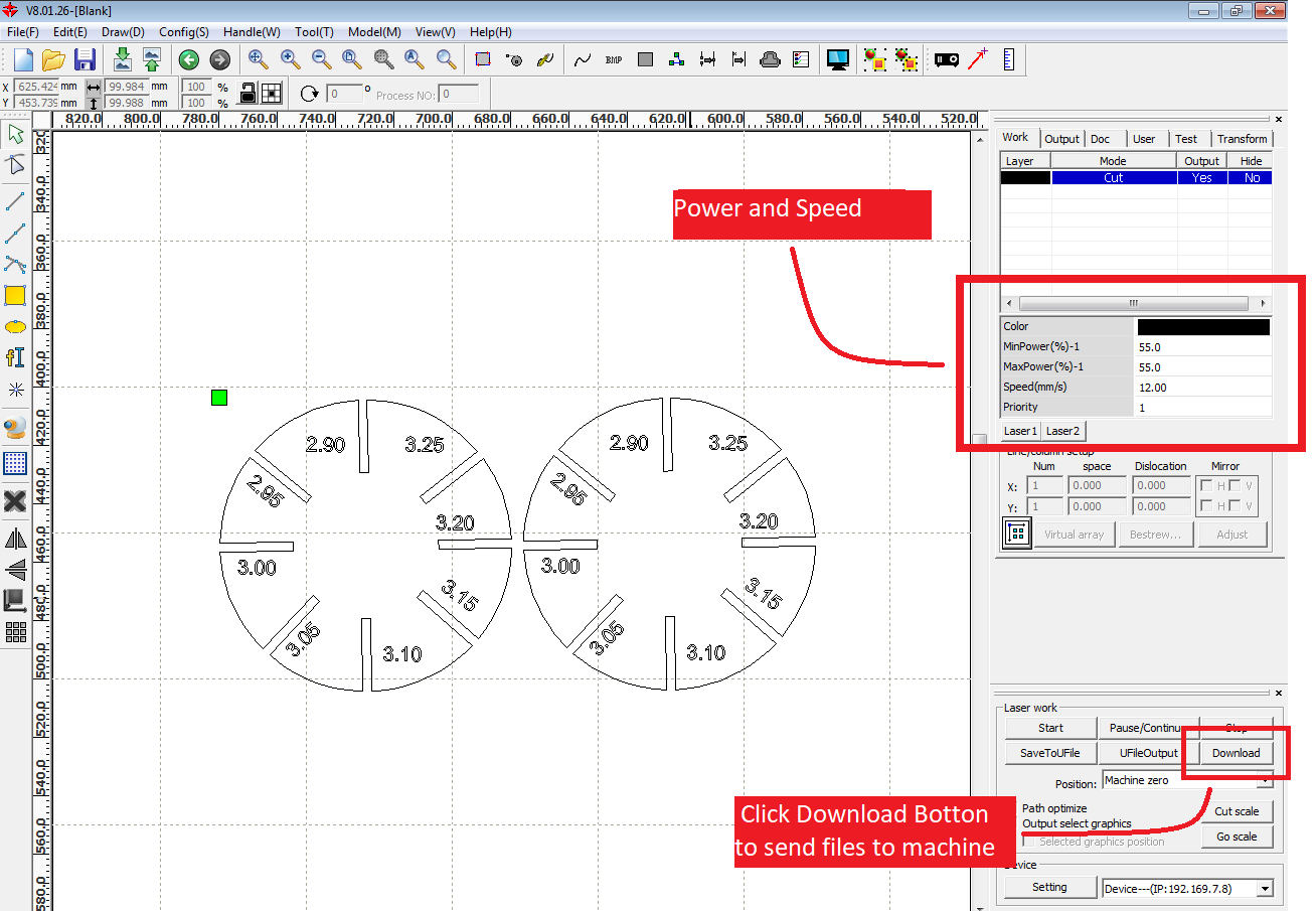
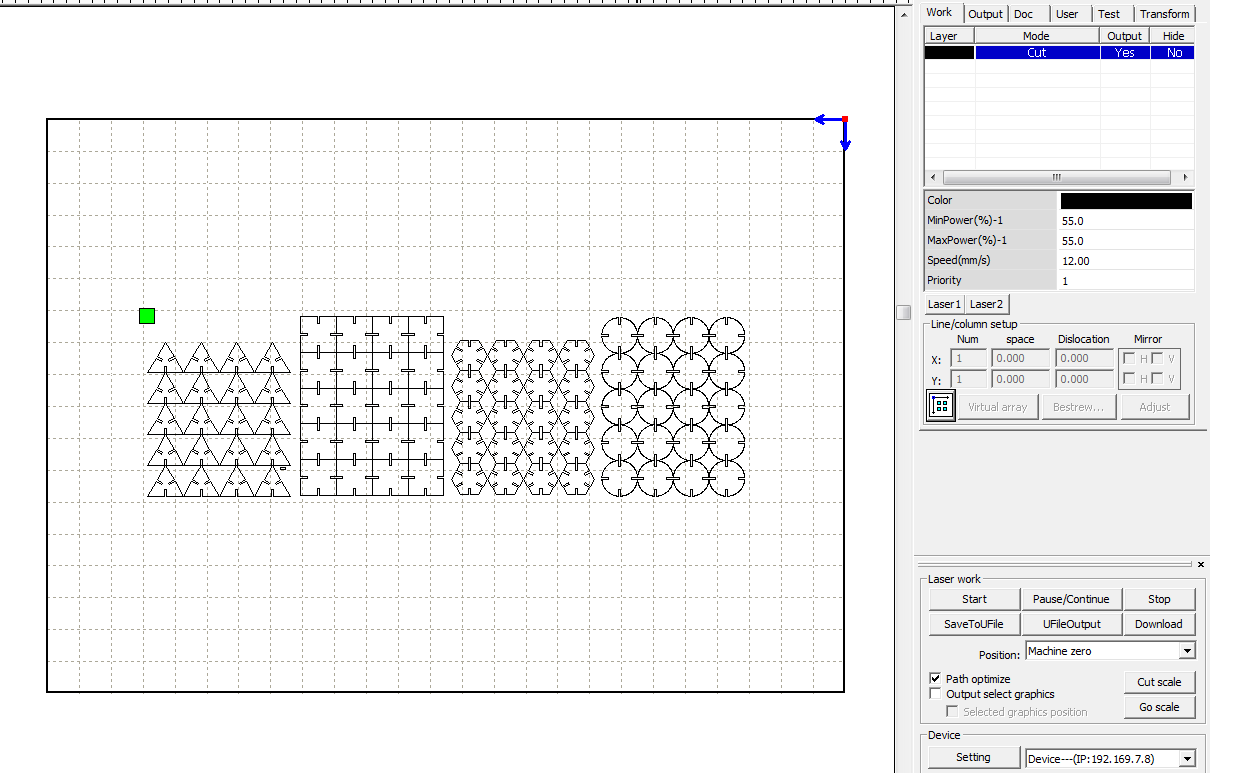
IN RD-WORKS
In Rd-Works there are sections for different tasks, listed Below.
Combine curve - for joining the curves if they are not
Delet overlays - For deleting the overlay lines
Curve Auto close - if one curve is not close itself, this tool will do that
Data check - will check above details by one click
Preview - Will simulate the toolpath
Power and speed settings :
POWER:
How much power in percentage will be provided to a machine
SPEED:  Speed of the machine while cutting
layer:  the layer will help to set the priorities in a different profile
Laser cut controlls
Start
Pause
Stop
download : the download will create a prepared file for laser cut and send data to the machine.

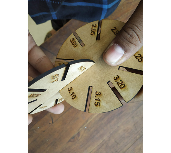
comb test
Laser cutting Machine
In laser cutting, we have SIL - laser engraver machine. it is co2 based laser engraving machine. since it is co2 based laser engraver it can not cut the metal, but it has good results with materials like MDF, plywood, Thin wood sheets, buff board, cement board, Acrylic. these are the MATERIALs I tried with the machine I placed details on group work.
OUTPUT FOR 3.25 MM MDF
On the comb test, I found, the thickness of the 3.10 will be perfect for my press-fitting kit. So my material kerf was 0.07 (One side of the notch)
RHINO AND grasshopper
During experiments, I found some problems with the Fusion-360. The software was taking to much load time when I was changing Parameters, it was beyond my machine's limitations so I go for Rhino and grasshopper.i was familiar
with rhino but I have no idea how to use it for parametric design, through it was for parametric designs I was sure I can use it for good. I saw last year's fab academy student Adhitya-ss documentation for any clue in parametric software.
I found a solution. this video is teaching to create Notches on geometry. I followed the whole process.
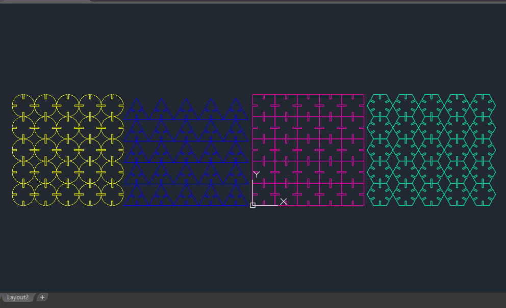
MAKING MODULES(SHAPES)
I was taking time to understand the Workflow of the grasshopper since it was very new to me but I figure it out somehow and started making processes
MAKING MULTIPLE MODULES
I am still figuring out the workflow of the grasshopper, and I tried different modules myself later.
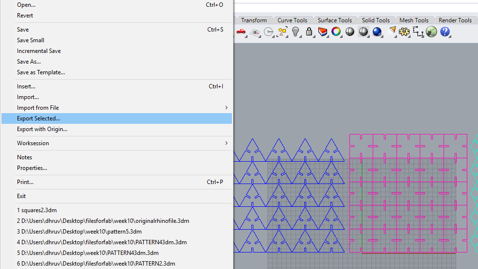
export File from rhino3d
Select "Export selected" option and select geometry, select Autocad(.DXF) format. then go to Options and select "natural 2007" version.
These methods are essential for our system. You can do some post-process on AutoCAD also.
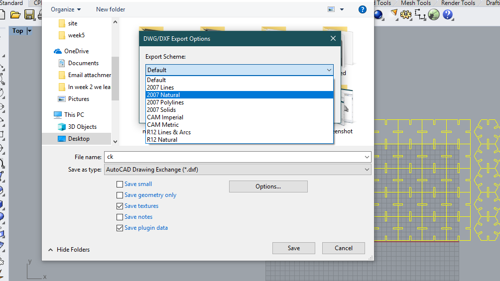
Dxf file
If you do some work on Autocad, like overkilling and joining better if Autocad file is exported on the 2004 version. Converting files into .DXF, it is the format that RD-WORKS can read. for our system, it is recommended to use .DXF 2004 version.
Dominant parameters
Talking about the dominant parameters in the design, there are two main two parameters which are dominant.
RDworks softwere

Laser cutting
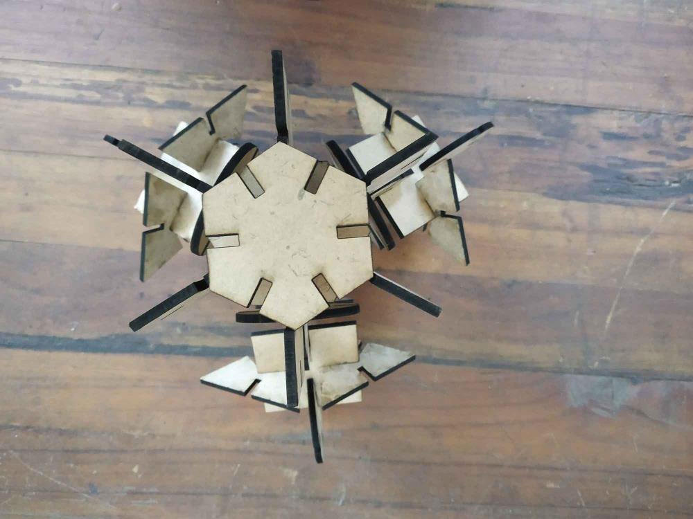
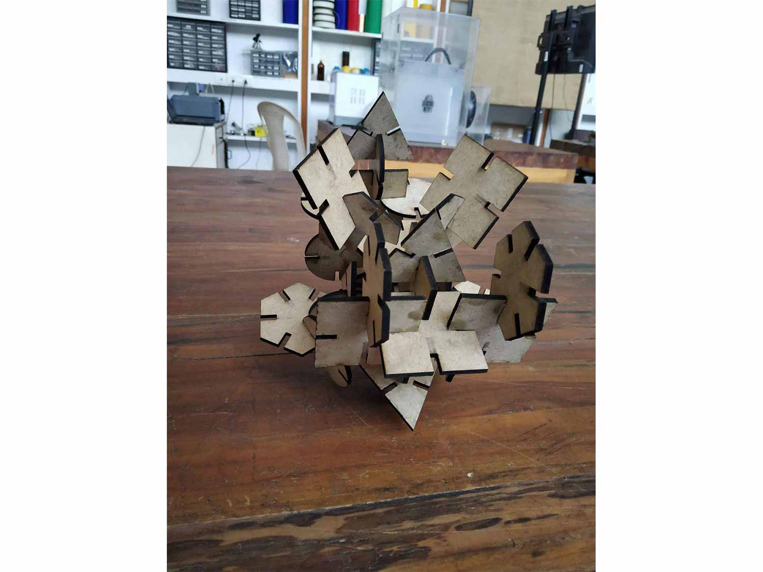
final parametric design
First construction


second construction

Group work
In a group work our role was to understand the Laser cutter and to do that by trying different operations like cutting, Etching, cutting on different power, and speed on the different
cutting paths ( Straight or curved ). everyone choose different material to test, I choose Acrylic. it is known for its transparency and elasticity.
Click here to redirect on group website .
Thickness of material: 1.5 mm
Power for Texts and etching: Power max: 7 % Power min: 40 %
Speed for text:	200 mm/s
Suitable for Etching: only up to 70 % power(IN SIL)
Minimum diameter can be cut: 1 mm
Kerfing: 0.07 mm
Minimum text can be cut: 1 mm
Living hinges: good material for living hinges

general conclusion about SIL :
COMPUTER CONTROLLED MACHINING WEEK
In computer control Machining week I have done some work in Parametric design and Laser cutting. In Week 8 I designed Plnatery gear Box. since I never made gears I wanted to understand it first in
real, so I made one prototype using the Laser cutter. The whole system is parametric so I don't have to redesign everything if something goes wrong.
Click here for week 8 page.
Conclusion
This week I finally started working with machines, I learned things which are very new to me and things I always wanted to do, to make it(my designs) work on real life. now computers are smart enough to make any type of 3d or 2d design we
want but one always has to think about some constrains and try to overcome creatively if they want designs in the physical environment. I think that I wanted to do so far and from this week I got a chance to do that.
in the vinyl cutter, I learn to control the speed and force to do cut part right, for more complex design one will also have to think about its easy and better removal.
in laser cutting, SIL is a very good laser cutter but it also comes with some limitations, limitations I have written on the group work sections. in my design, Kerfing was only limiting parameters that can affect
the construction. the overall week was good. :)