Week 12 : Assignment
- add an output device to a microcontroller board you've designed, and program it to do something
In week 12 assignment was to add an output device in microcontroller and I have to program it to do something ! I thought it will be a good idea to use the input devices I used in week 11.
All Details of 328p board is uploaded in week 11.
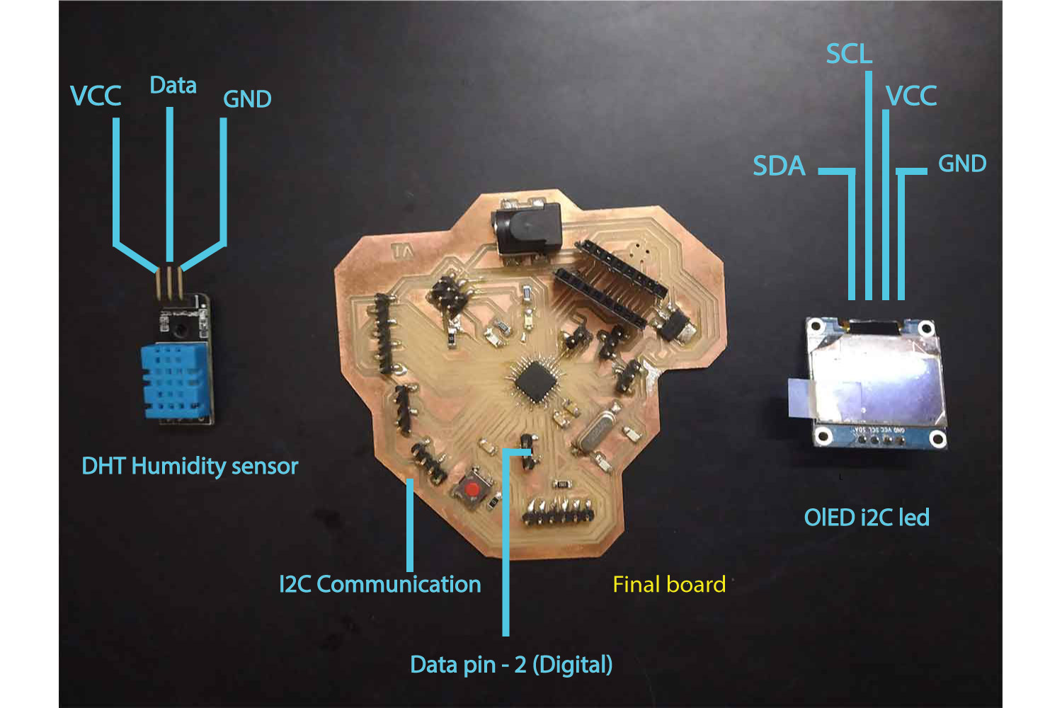
Humidity sensor with OLED
I already used the humidity sensor and print details on serial Monitor, I wanted to print them on my OLED now.
OLED (Organic Light-Emitting Diode) is a self light-emitting technology composed of a thin, multi-layered organic film placed between an anode and cathode. In contrast to LCD technology, OLED does not require a backlight. OLED
possesses high application potential for virtually all types of displays and is regarded as the ultimate technology for the next generation of flat-panel displays. my
reference for this code.
Click here to know more.
setup
in setup, I connected
Code
I got these codes from Random Tutorials and About OLED and DHT sensor. I still needed to understand this code, I wrote in every comment what each line is doing, the way
I understand...The below code will show Humidity and temperature.
Don’t forget to include
  /*
  * Random Nerd Tutorials - Rui Santos
  * Complete Project Details https://randomnerdtutorials.com
  */
  // require libraries one will need to run the code

  #include <Wire.h> // wire library for I2C communication

  // Adafruit library for the OLED printing
  #include <Adafruit_GFX.h>
  #include <Adafruit_SSD1306.h>

  #include <DHT.h>// library for Dht sensor

  #define DHTPIN 2 // digital pin is defined to humidity sensor
  #define DHTTYPE DHT11 // defined reading
  #define OLED_RESET 4 // OLED HAS TO DEFINE RESET IN EVEN IT IS NOT IN PINOUT
  Adafruit_SSD1306 display(OLED_RESET); //FOR DISPLAY

  // Initialize DHT sensor
  DHT dht(DHTPIN, DHTTYPE);

  void setup() {
  Wire.begin();
  dht.begin();
  display.begin(SSD1306_SWITCHCAPVCC, 0x3C);// initialize with the I2C addr 0x3C
  }

  void displayTempHumid(){
  delay(2000);
  // Reading temperature or humidity takes about 250 milliseconds!
  // Sensor readings may also be up to 2 seconds 'old' (its a very slow sensor)
  float h = dht.readHumidity();
  // Read temperature as Celsius
  float t = dht.readTemperature();
  // Read temperature as Fahrenheit
  float f = dht.readTemperature(true);

  // Check if any reads failed and exit early (to try again).
  if (isnan(h) || isnan(t) || isnan(f)) {

    // if sensor failed to received any of three data it will fullfill this condition, if readings are available it will skip this loop

    display.clearDisplay(); // clearing the display
    display.setTextColor(WHITE); //setting the color
    display.setTextSize(1); //set the font size
    display.setCursor(5,0); //set the cursor coordinates
    display.print("Failed to read from DHT sensor!");
    return; // it will return to start if condition fulfilled
  }


  display.clearDisplay();
  display.setTextColor(WHITE);
  display.setTextSize(1);
  display.setCursor(0,10);

  // prints on display from below

  display.print("Humidity: ");
  display.print(h);
  display.print(" %\t");
  display.setCursor(0,20);
  display.print("Temperature: ");
  display.print(t);
  display.print(" C");

  // you can get tempreture values from below in fahrenheit

  //  display.setCursor(0,20);
  //  display.print("Temperature: ");
  //  display.print(f);
  //  display.print(" F");
  }
  void loop() {
  displayTempHumid();
  display.display();
  }
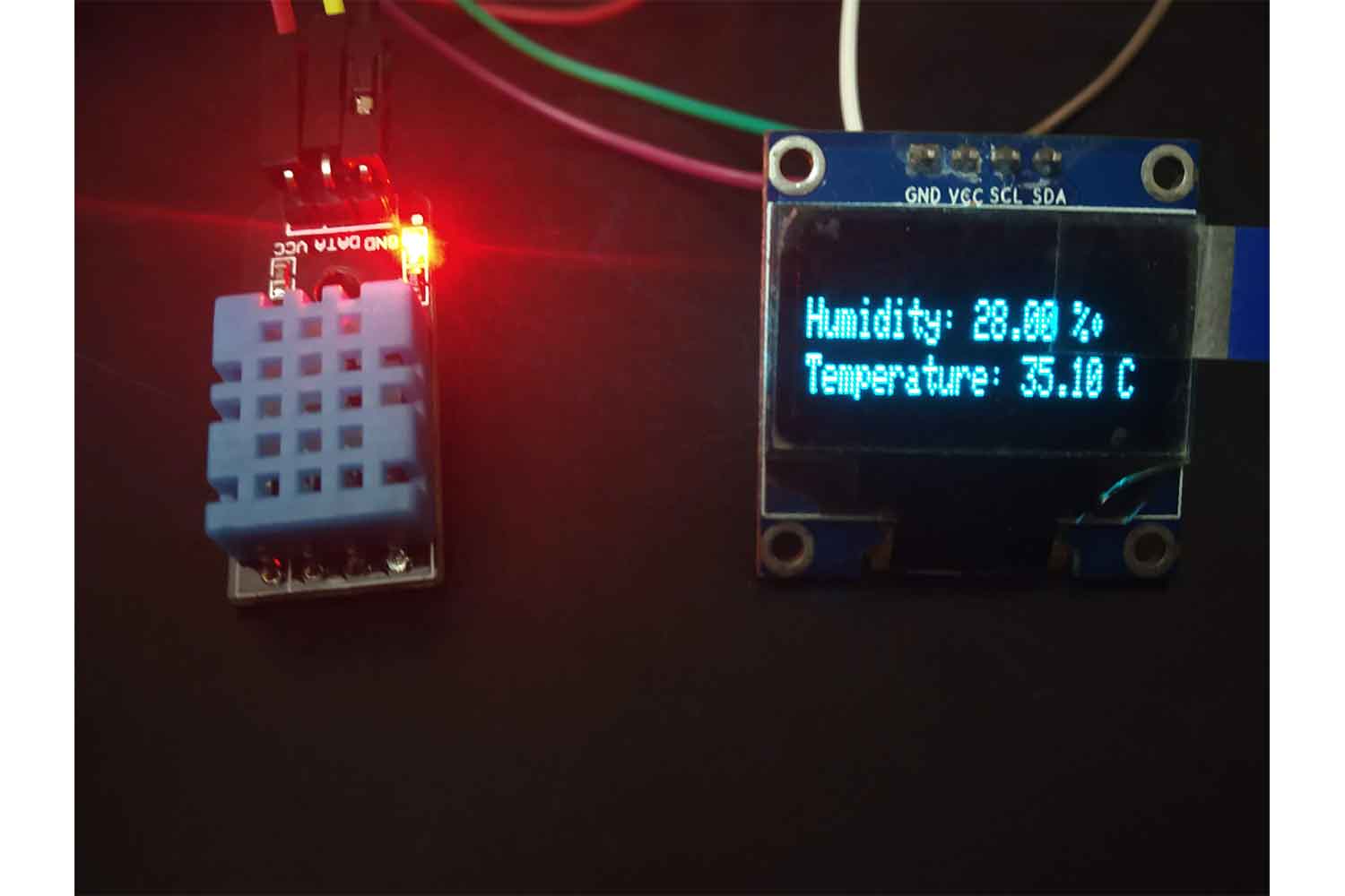
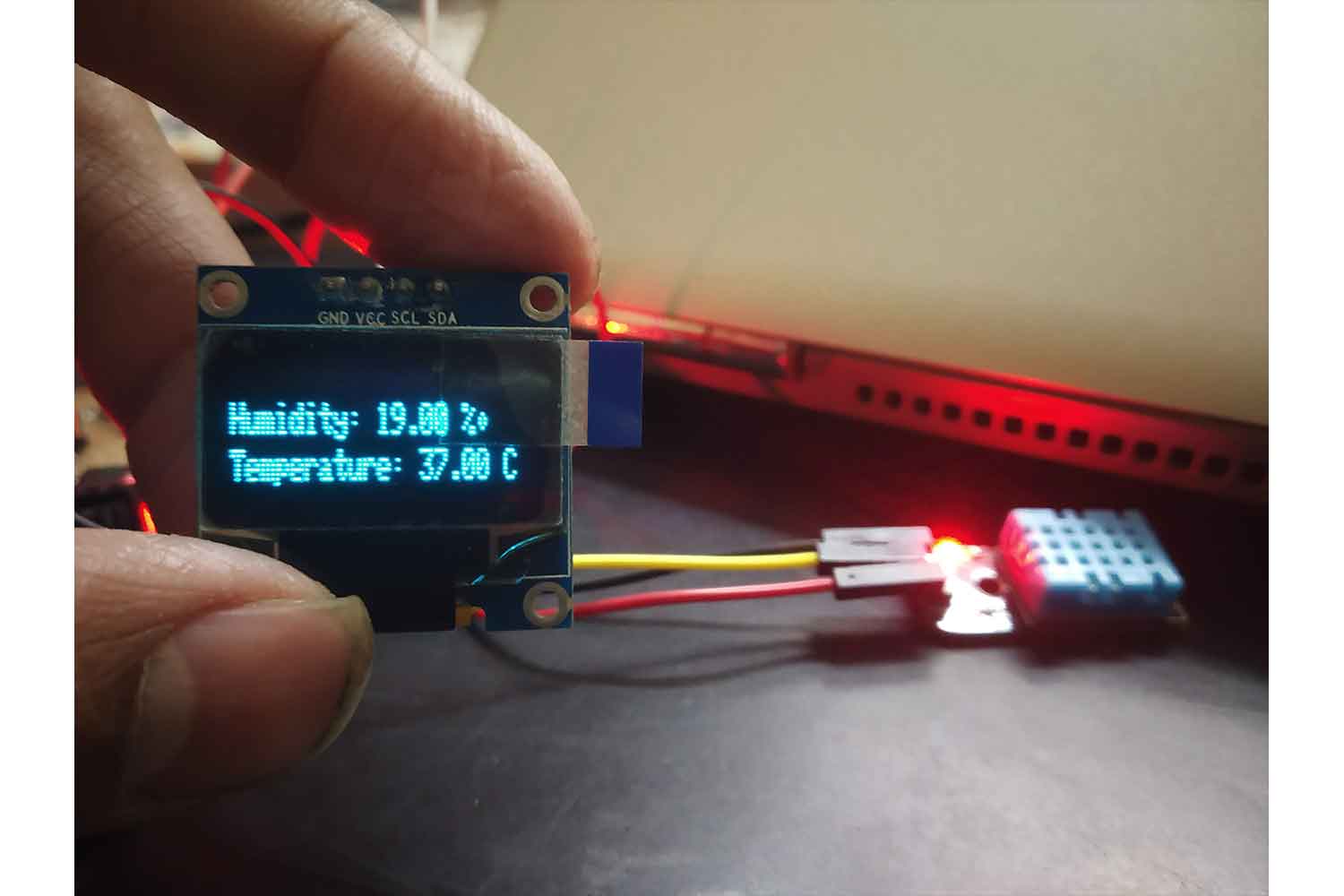
Output
Below I am trying to increase the humidity with a wet Handkerchief, see Below in video!
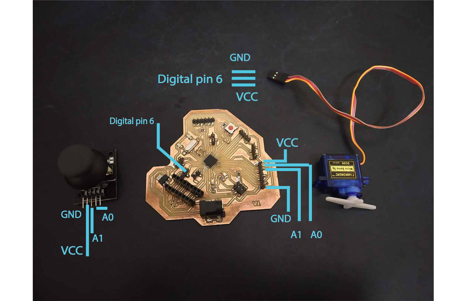
Servo motor with the Joystick
Then I tried to run Micro-servo with joystick module!Setup
Joystick connected to (A1,A0) // Vrx, Vry
servo pin 6
Code
II explained code in the comments, I thought it would be a more efficient way, for simplicity copy code in Arduino and read, it will be more clear there.
Don’t forget to add a library of servo below.
  #include <Servo.h>

  // including servo library

  Servo servo1;
  // define servo name

  // initialize variables and define pins
  int x_pos;
  int y_pos;

  // Define pin for servo, define PWM pins
  int servo1_pin = 6;
  int initial_position = 90; // defined initial position, wanted to rotate both side

  // set initial numbers
  int xPosition = 0;
  int yPosition = 0;
  int SW_state = 0;
  int mapX = 0;
  int mapY = 0;
  int VRx = A1;
  int VRy = A0;
  int SW = 8;

  void setup ( ) {
    Serial.begin (9600); // defining the input and output pins
    servo1.attach (servo1_pin );
    servo1.write (initial_position);;
    pinMode(VRx, INPUT);
    pinMode(VRy, INPUT);
    pinMode(SW, INPUT_PULLUP);
  }

  void loop ( ) {
    // cod is reading joystick x and y axis readings
    xPosition = analogRead(VRx);
    yPosition = analogRead(VRy);
    SW_state = digitalRead(SW);


    // printing on serial monitor
    Serial.print("X: ");
    Serial.print(mapX);
    Serial.print(" | Y: ");
    Serial.print(mapY);
    Serial.print(" | Button: ");
    Serial.println(SW_state);

    delay(100);

    x_pos = analogRead (xPosition);    // reading position for servo control

      // below code dividing the values in two segments, (0,300) and (700,1023).

      // first part, lets say it is for rotation servo anti-clockwise code

      /* Below if position comes below 300 */
      if (x_pos < 300){
      if (initial_position < 10) {
        } // first it will check it is below 10 or what, if it is it will do nothing and forward the loop
      else{

        /* else it will decrease the data by 10, and new servo position will be available, this position values
          will be added or decrease depends on the readings
        */

        initial_position = initial_position - 10;
            servo1.write ( initial_position );
            delay (120); }
        }

      // second segment if values are greater then the 700, it will run servo to rotate oposite side

      if (x_pos > 700){
      if (initial_position > 980)
      {
      }
      else{
            initial_position = initial_position + 10; // it will just increase the values
            servo1.write ( initial_position );
            delay (120);
          }
       }


   // same things for y

        if (y_pos < 300){
      if (initial_position < 10) {
        }
      else{ initial_position = initial_position - 10;
            servo1.write ( initial_position );
            delay (120); }
        }
      if (y_pos > 700){
      if (initial_position > 180)
      {
      }
      else{
            initial_position = initial_position + 10;
            servo1.write ( initial_position );
            delay (120);
          }
       }
  }
video
Group work
in group work, we have to measure the power consumption of any output component possible. we measured Power Consumption for a BLDC motor. In this group work, we don’t need to divide specific tasks! we did it together so.
Check group website for more information.
- For lower speed around 12, power consumption was 2.54 w (0.212 A on 12 v )
- For highest speed around 140, power consumption was 8.412 w (0.701 A on 12v)
Conclusion
This week made input week complete, learned I could use an input device to get different types of outputs.