Week 7 : Assignment
- redraw the echo hello-world board, add (at least) a button and LED (with current-limiting resistor)
- add (at least) a button and LED (with current-limiting resistor)
- check the design rules, make it, and test it
In week 7 we are going to design our Echo hello-world board using Eagle or Kicad and we have to fabricate it. we have to attach an LED and button to the circuit to check the working of the micro-Current, Voltage,
Resistance.
I am familiar with them because in mechanical we are quite used to deal with Electronic fundamentals(Theories) but applying it in real life or something I am going to use in my final project it was a different thing.
What is Circuit ?
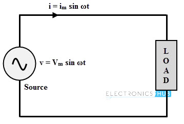
In Electronics, a circuit is a path between two or more points along which an electrical current can be carried. This circular path, which is always required to get electricity to flow and do something useful, is called a
Circuit A circuit is a path that starts and stops at the same place.
*Benjamin Franklin originally wrote that electricity flows from the positive side of a voltage source to the negative side. However, Franklin had no way of knowing that electrons flow in the opposite direction - at the atomic level, they
come out of the negative side and loop back to the positive side. Because engineers followed Franklin's lead for hundreds of years before the truth was discovered, we still use the "wrong" convention to this day. Practically speaking this
detail doesn't matter, and as long as everyone uses the same convention, we can all build circuits that work just fine.
I get to learn some terms like Load, Short circuit, open circuit.
What is load ?
These things are called loads because they “load down” the power supply. it’s possible to load down a power supply too much, which will slow down the current flow, it’s also possible to load down a circuit too little - this may let too much current flow (imagine running too fast if you weren’t carrying any weight), which can burn out your parts or even the power supply.
What is short circuit ?
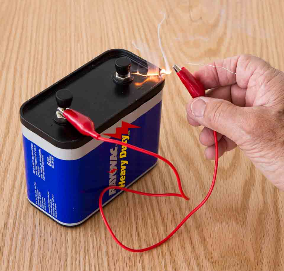
If you directly connect positive and negative power supply. you'll create what is called a short circuit.
If you do have a load in the current, the current flow through your circuit will be limited to that which your device consumes, which is usually a very small amount. However, if you don't put anything in to restrict the current flow,
there won't be anything to slow down the current, and it will try to be infinite!
Your power supply can't provide infinite current, but it will provide as much as it can, which may be a lot. This could cause your wire to burn up, damage the power supply, drain your battery.
Most of the time
your power supply will have some sort of safety mechanism built into it to limit the maximum current in the event of a short circuit, but not always. This is the reason all homes and buildings have circuit breakers, to prevent fires from
starting in the event of a short circuit somewhere in the wiring.
What is integrated circuit ?
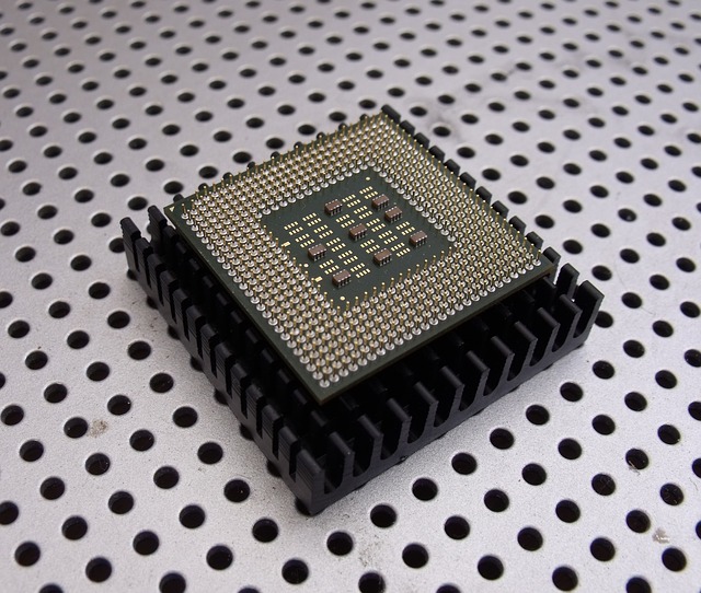
An integrated circuit, or IC, is a small chip that can function as an amplifier, oscillator, timer, microprocessor, or even computer memory. An IC is a small wafer, usually made of silicon, that can hold anywhere from hundreds to millions
of
transistors, resistors, and capacitors. These extremely small electronics can perform calculations and store data using either Digital or Analog technology.
Every electronic appliance we use in our day-to-day life,such as mobile phones, laptops, refrigerators, computers, televisions and all other electrical and electronic devices are manufactured with some simple or complex circuits.
Electronic circuits are realized using multiple electrical and electronic components connected with each other by connecting wires or conducting wires for the flow of electric current through the multiple components of the circuit, such
as resistors, capacitors, inductors, diodes, transistors, and so on.
source
echo hello board
This week's assignment was to make Echo hello board with One led and push button. The goal is to control the led blinking with the micro-controller and make communication with a laptop or computer with the micro-controller with the help of the Push-button.
Original Echo hello board.
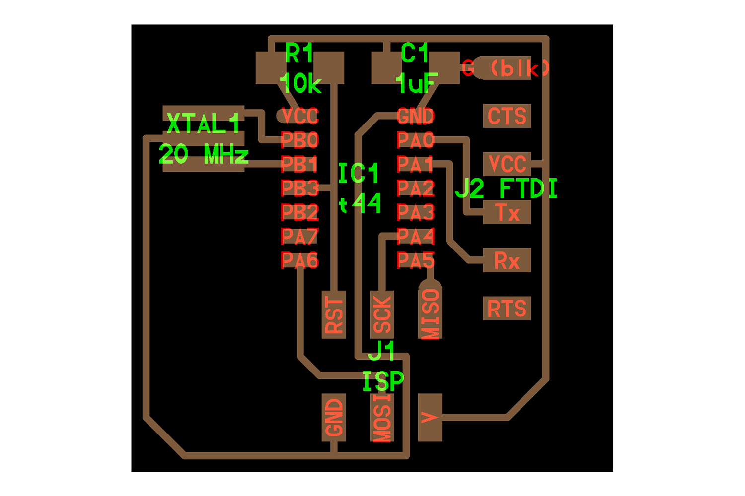
Component List
ATtiny44 (echo hello board) - Microcontroller - Microcontroller is a small computer on a single integrated circuit. it will take command in the sense of programs and execute them physically with the help of various components attached to it.
FTDI-SMD header - For serial communications, this header is used for the Asynchronous serial communication.
Resonator - 20 Mhz - For Generating specific clock speed to transfer data, a clock is necessary for transmitting the data in Synchronous serial communications
AVRISP header pin - To program the micro-controller, as Asynchronous communication uses the FTDI pins, for Synchronous communications these header pins are used. interface is Serial Peripheral Interface
Pull out Resistor - 10k - pull-outs voltage from the microcontroller for safety, these resistors will be found in any circuits. their function is to give the reset pin High voltage. if the pin is given low voltage it will reset the microcontroller, we can do intentionally by putting switch there.
Power Filtering Capacitor - 1uf - Filters the power input which will go into the micro-controller, should be kept near the MCU as possible as can be.
Terms
Vcc - 5-volt input
GND - Basically, GND is the reference Line from which VCC is measured. Like pressure, we don't measure the direct value of it because it doesn't matter, what we need is pressure Difference from reference. Same with Voltage difference.
MOSI - Master out and slave input
MISO - Master in and slave out
RST - RST pins are used for resetting the microcontroller while programming.
SCK - Serial Clock pin. Click here to know These terms in details.
Tx - It's for transfer of data from the Master( Computer, programmer ).
Rx - It's for Receiving data to the Master( Computer, programmer ) from the program.

TX and RX will be with respect to the Master
Trace and Cut File
This is the original design of the Echo hello board. These are the minimal design components which mean every Microcontroller will need these components to be Programmed, to be
Communicate with other boards, and to Do their specific task.
Click here for Trace file And Cut file.
Additional components
Below are additional components I will need to make the Led blink with the Switch.
LED - To get outpoot indication
SWitch - for blink the LED with pc and communication purpose with PC in "Echo hello Code"
ATTiny44 Pinout
Click here, to know the source.
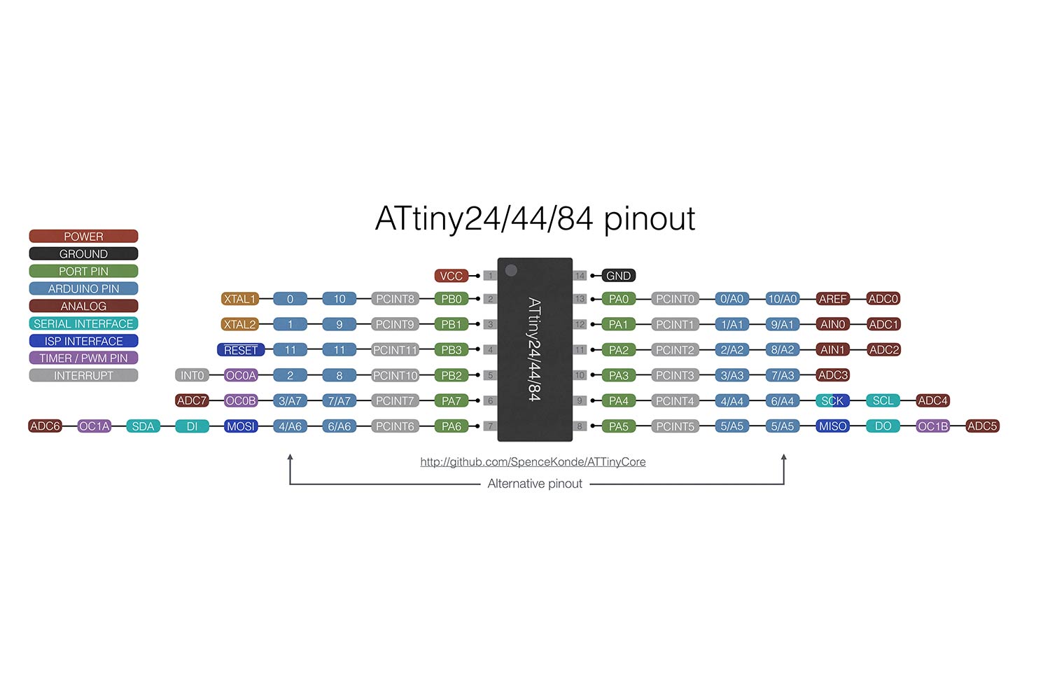
Pins description
Vcc - 5-volt input
GND - reference voltage - consider Zero
Port Pins - These are the pins that can be used for input and output. These pins some of have a special purpose. pins that can be used for the SPI interfac or Serial communication using RX and TX as I have written above in terms.
Arduino pins - These pins Indicate Arduino pin number, If one is using Arduino IDE for the programming the PCB board this pin will be used.
Analog pins - All the pins of the Attiny44 can be used as the Analog input, except VCC, GND, RESET, Pin8(PWM pin).
Serial interface Pins - SDA and SCl pins. pins are used for communication protocol I2c. Here is a link for compare communication protocols(I2C, SPI, Asynchronous).
SPI interface pins - MOSI, MISO, SCK, RST Pins for the serial interface
Timer and PWM pins - These pins can be used for the Pulse generation and oscillator applications in an electric circuit. PWM is a very interesting one, which can modify the duty cycles of zero and one state. Click here to understand the PWM.
Interrupt pins - In a simple way, I understand this pin can Pause the program if some interrupt is accurate and start them automatically when it's gone. Click here to understand.
Schematic Diagram
Note :
The below procedure is general for making any Circuit design, Since electronics is new to me I failed at some point while making my PCB design. I have written what goes wrong and how it can be improved but for saving time I will redirect you to final output.
Pcb Design on Autodesk-Eagle(version 8.0.1)
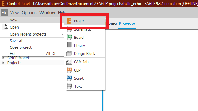
go to File > New > Project.
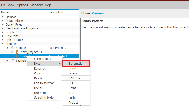
Open schematic
Follow the below image and Right-Click and go to New and Select Schematic.
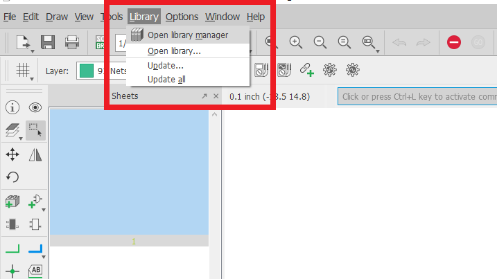
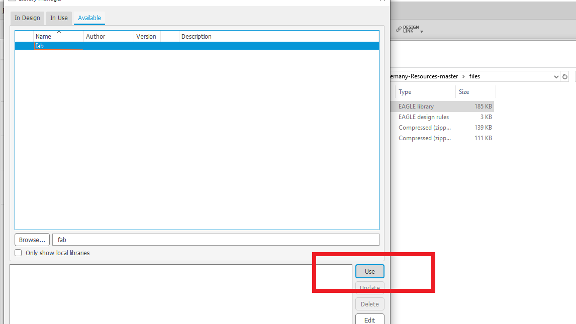
Include Fab-Library(Link!)
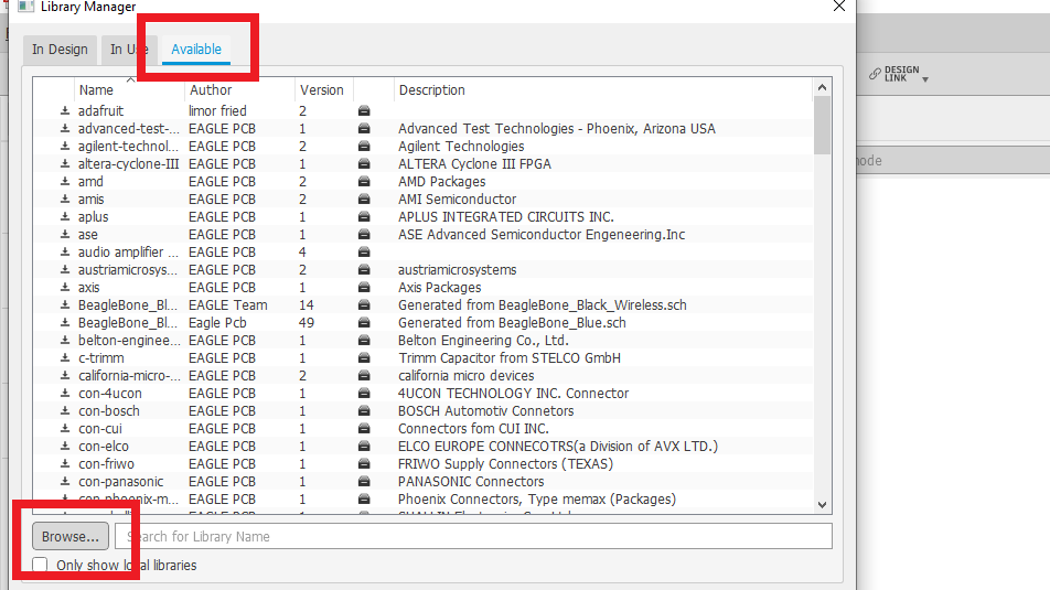
Click on the library and open the library manager. Go to Available and search the location of the Fab library. Select it and click Use.
Follow below steps.
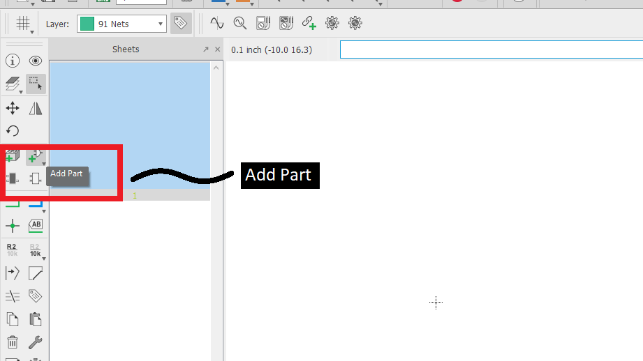
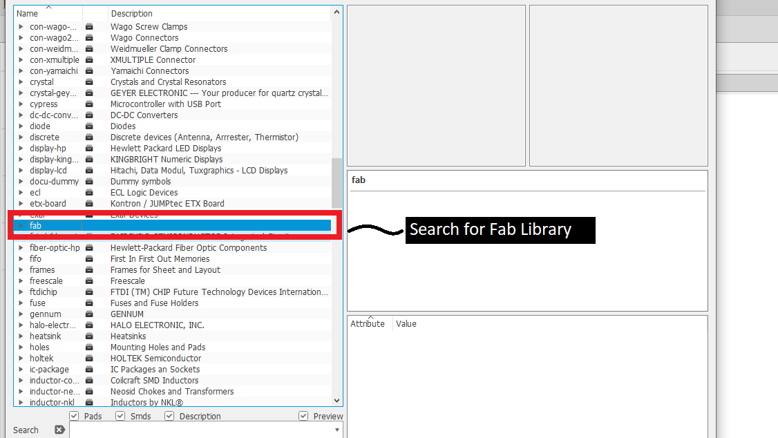
Add components
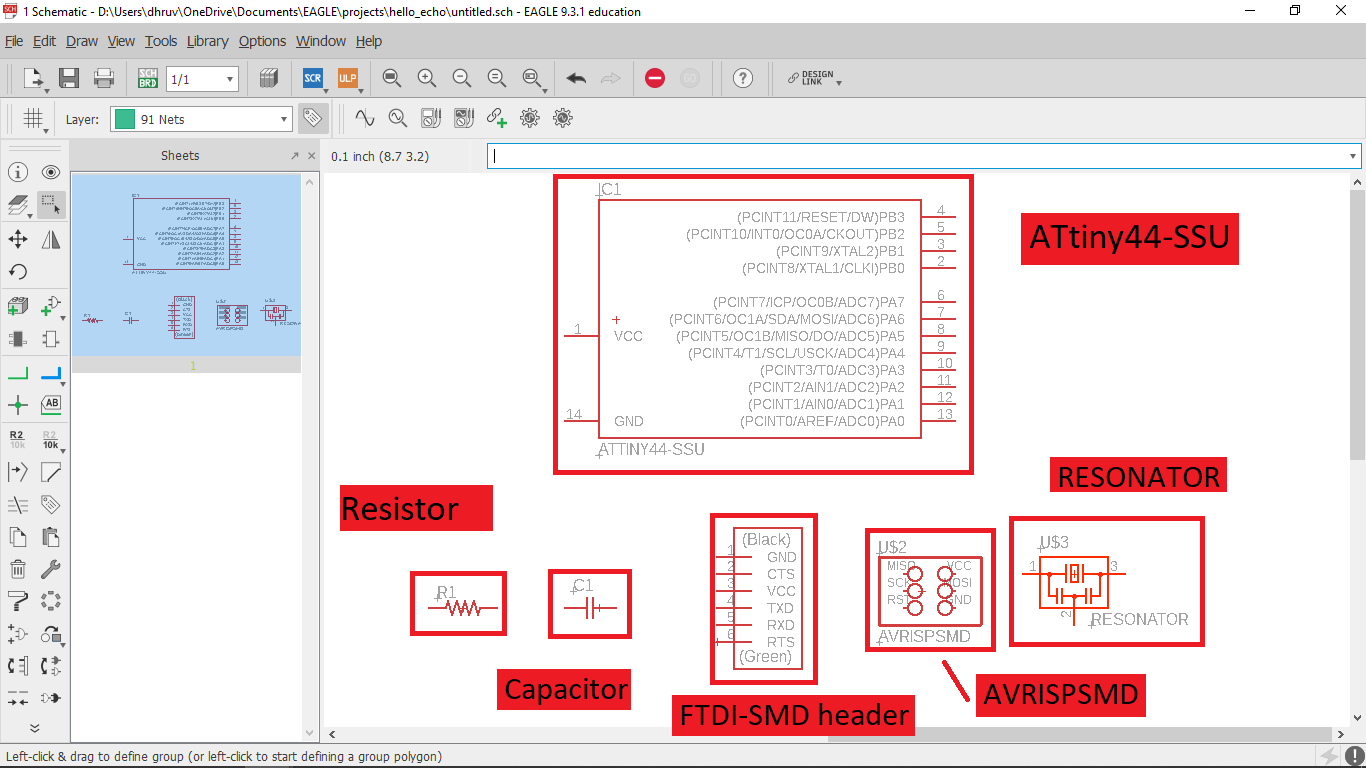
Click Parts to add components. Search for the fab library, there are many built-in libraries here but we are recommended to use Fab-library to make sure availability of the Components.
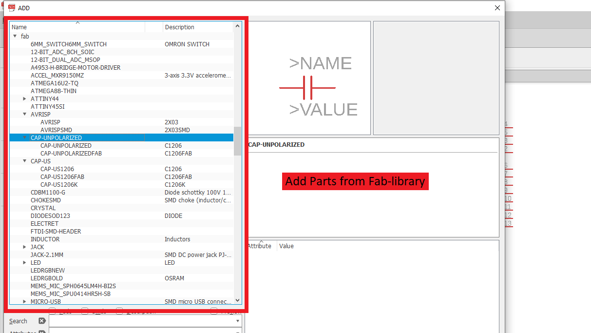
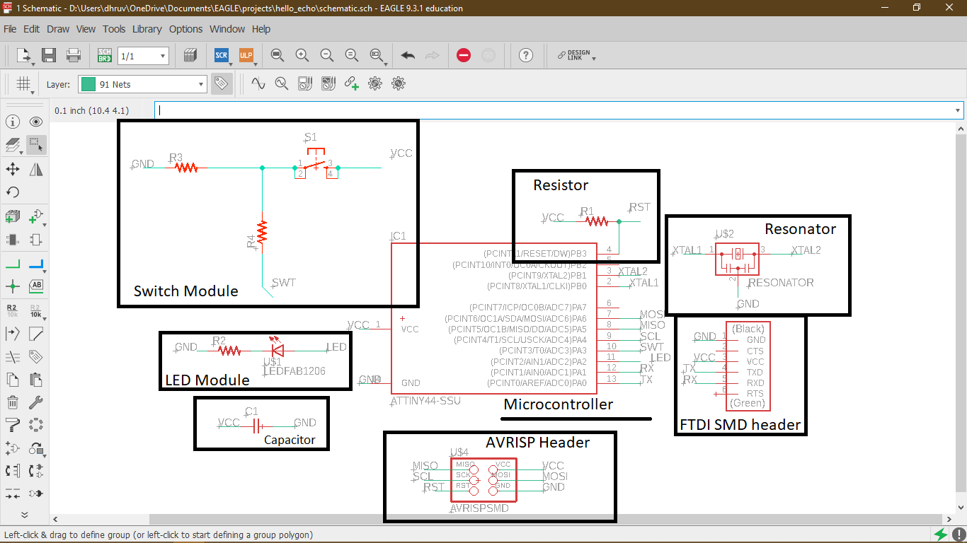
General components
These components are essential to program the controller or to work with any microcontroller.
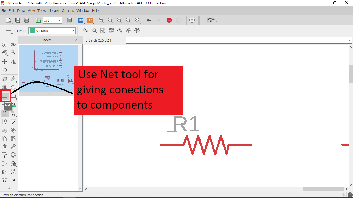
Net tool
What Net tool do is, it gives connections between the components, its just like virtual wires which help us to visualize the circuit better and try to give a perfect explanation of how the components on the circuit board are connected.
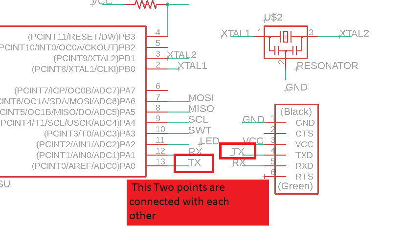
Name tool
You can connect the components by directly joining both the components with nets or by giving a specific name on each side of the net with the Name tool. These names help us to connect the components without making it complex.

Additional components
LED and Switch are additional components.
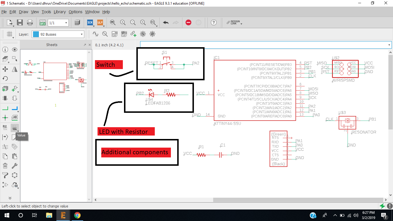
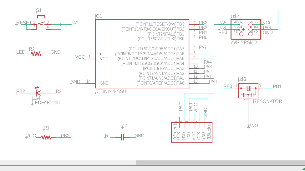
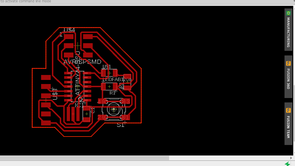
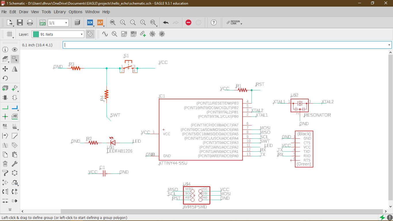
Complete Schematic
This is a complete schematic of my first design, I Request not to follow this schematic if you are, I made mistake on schematic since I had no information of where to put the Switch I put it on rest pin and its functionality will change It will reset the board instead of controlling the LED, I will redirect you to working schematic. as I was designing the first time I was not sure about these mistakes, so I kept on and mad one board.
Mistakes
I gave names improperly.
I connected my switch with the reset pin of the microcontroller, It will not full-fill my objective here (it will not give a signal to pc instead it will reset my micro-controller, which is a good thing for big boards or different applications).
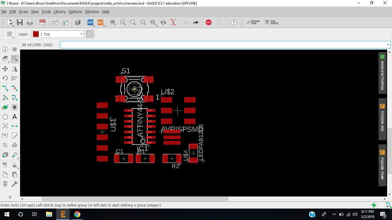
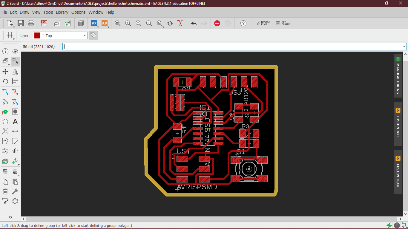
Generate board diagram
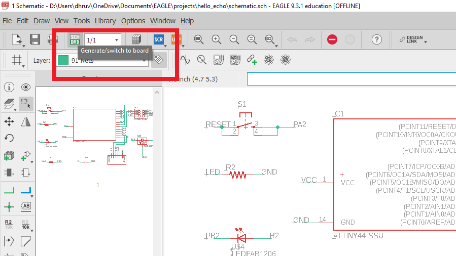
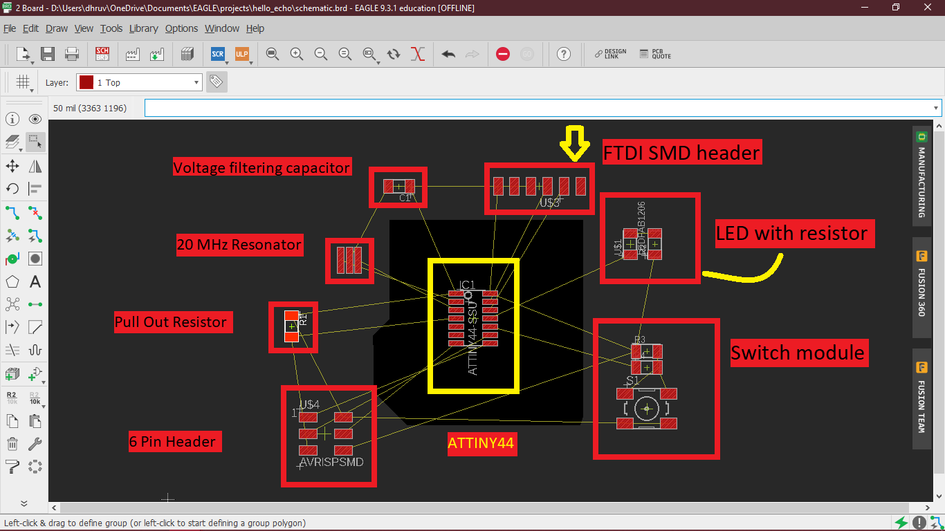
Arranging components
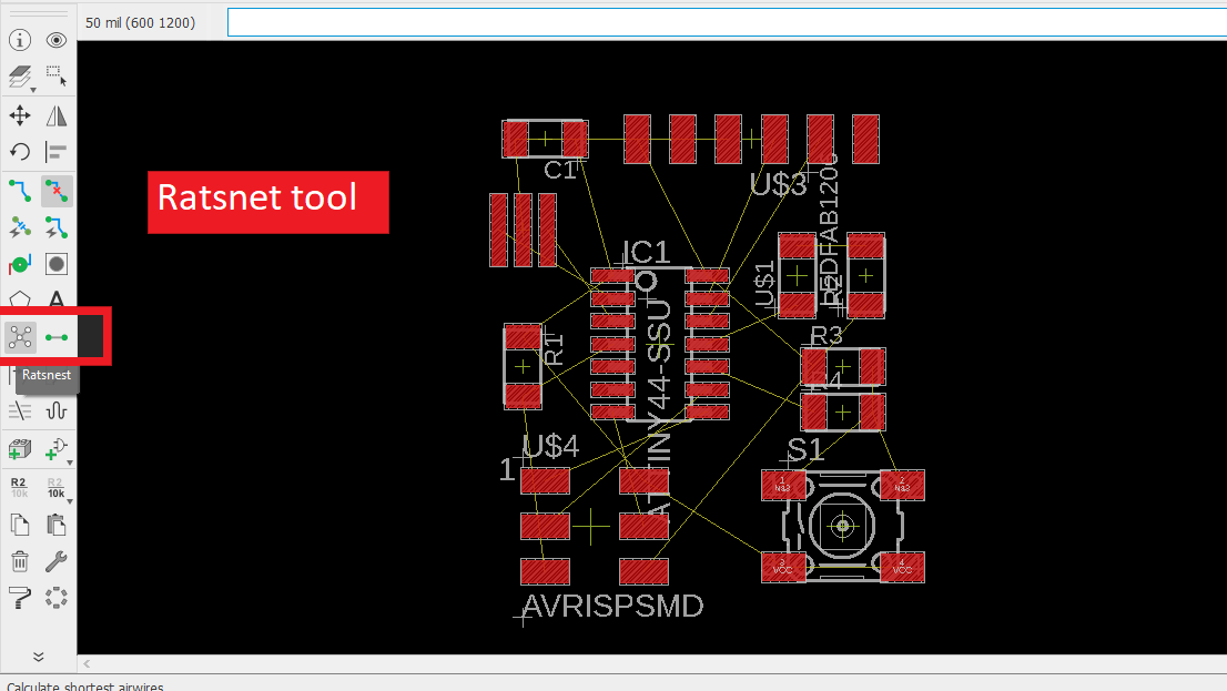
Ratsnet tool
Arranging the components for the circuit, inboard diagram we arrange the components the way we want to see than real output.
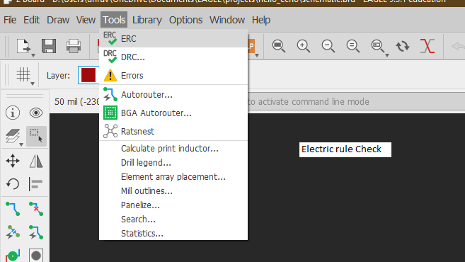
Design rule checks
Electric rule check (ERC)(link!)
It generally checks the schematic of our electric design. It compares Schematic with the general rules of electric circuits.
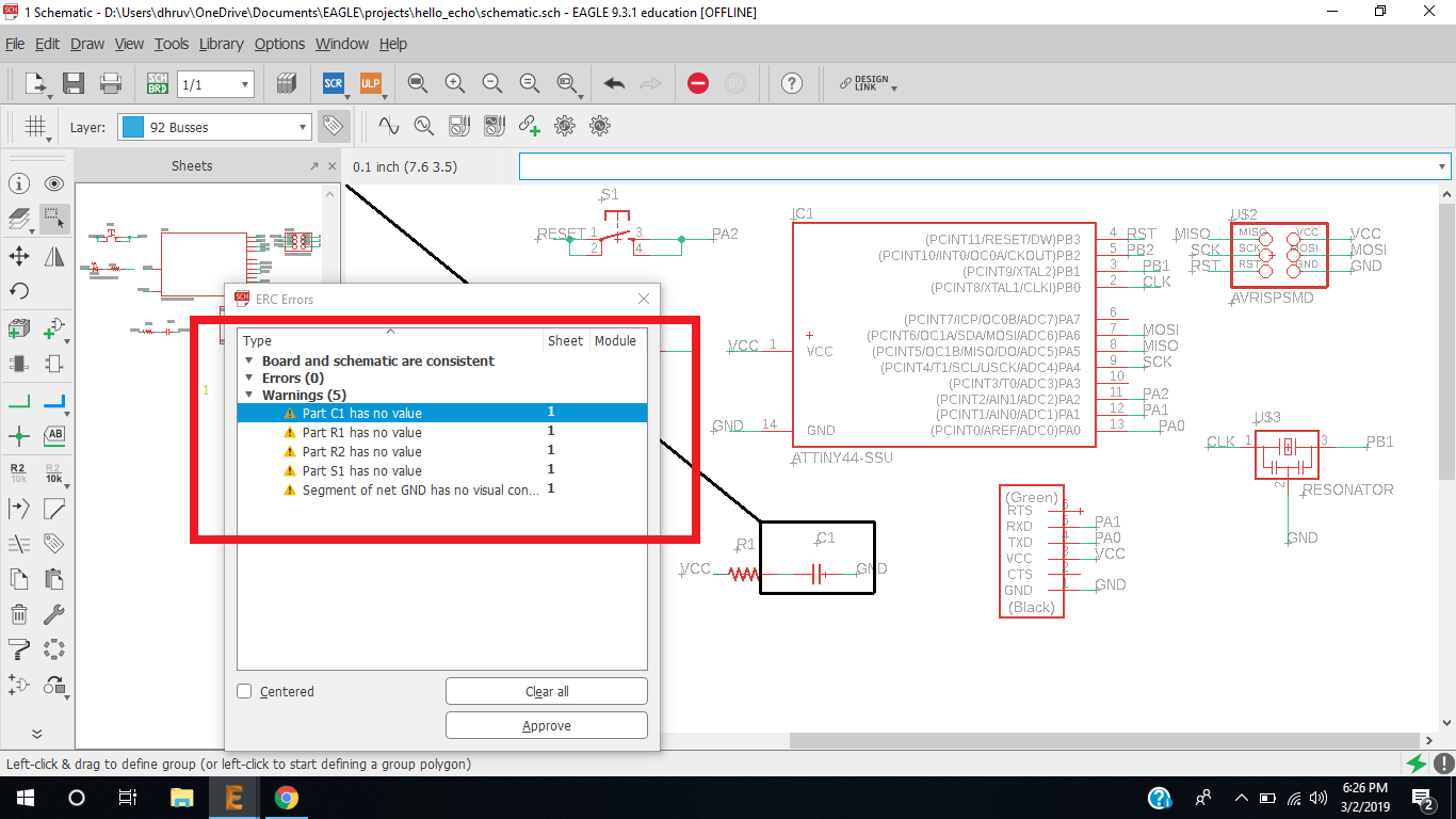
Schematic errors
I got some schematic errors, Error was for values, if you are simulating the circuit or giving the schematic to another person or if you are going to use it after some time, you got to put values there, I didn't because I was experimenting. for pulling out resistor and power capacitors I have given the values above. and I am going to use a 10k Resistor with LED.
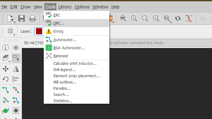
STEP 13 : Design rule check (DRC)(link!)
Open DRC check.
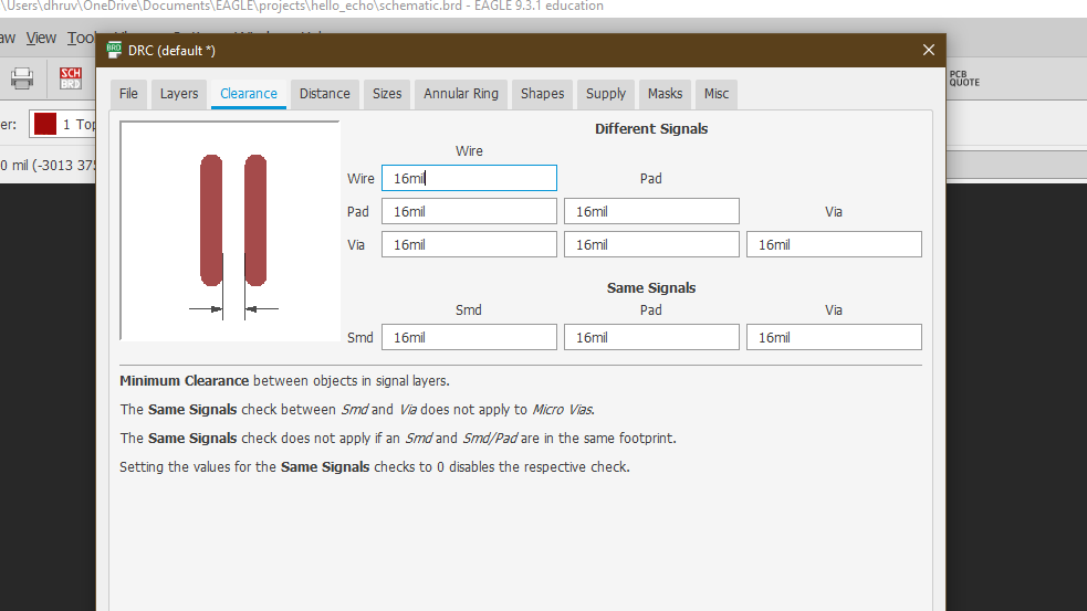
Settings in Clearance
Mil - Mil is dimention for traces, it is 1000th(1/1000) of Inch
Wire - It is representing the Copper wire traces
Pad - Pads on which electric components will be mounted
Via - Its through hole Diameter.
Below is the Clearance section. you can decide How much clearance you will need between these Wire, Pads, Via.. I gave the setting to 16 mill because in tracing I am using 1/64(0.4mm) = 16 mil tool so , in fab modules it can generate the toolpath.
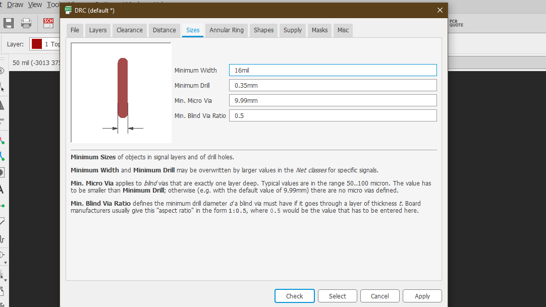
Traces width
To ensure the minimum trace width to be safe side, I kept Trace size to 16 mil. Other settings are default in DRC then CLICK check to ensure that your board diagram is Following DRC criterion.
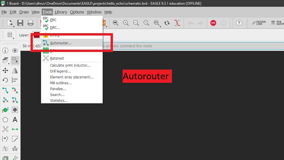
STEP 14 : Autorouting
Auto-routing is a tool that helps to generate the traces automatically by using mathematical functions. The autorouter is a useful tool that creates many routing variations for the current component placement. However, it is not a complete replacement for the manually routing method. It can help you in specific situations to augment your abilities, not replace them. (link!). Open the auto-routing path for generating traces automatically.
Require Settings
Give this required Settings.
Efforts - How Much efforts do you want from computer to creat routing, It will effect your time and computing power of computer.
Bottom - If you are not using Two side pcb Keep it two none.
Number of threads - how many threads of the CPU you want the autorouter to use? This surely will affect the time it takes to finish. Click here to know more.
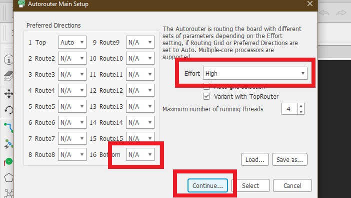
Rounting grid - How many attemps you want your computer to do on Auto routing I kept it 16.
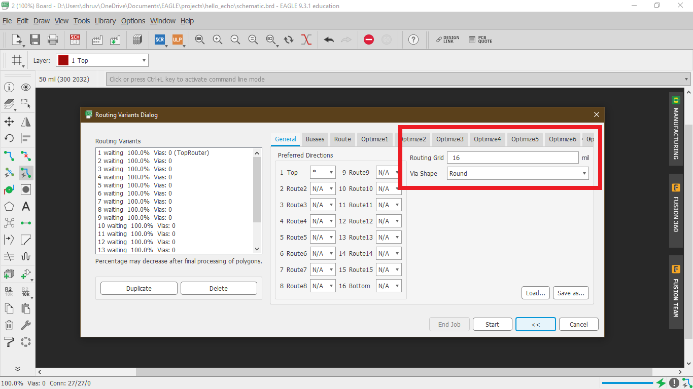
Choose 100% autorout
Choose the 100% option and press End job, (It will be not easy to get 100% Path connections though).
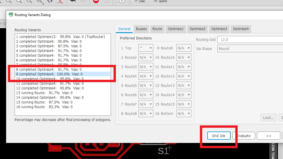
Note :
If you are not getting 100% you can place the components on a different location to generate 100% Routing, for that you have to remove old generated traces, you can write the "ripup;" command on the command line.
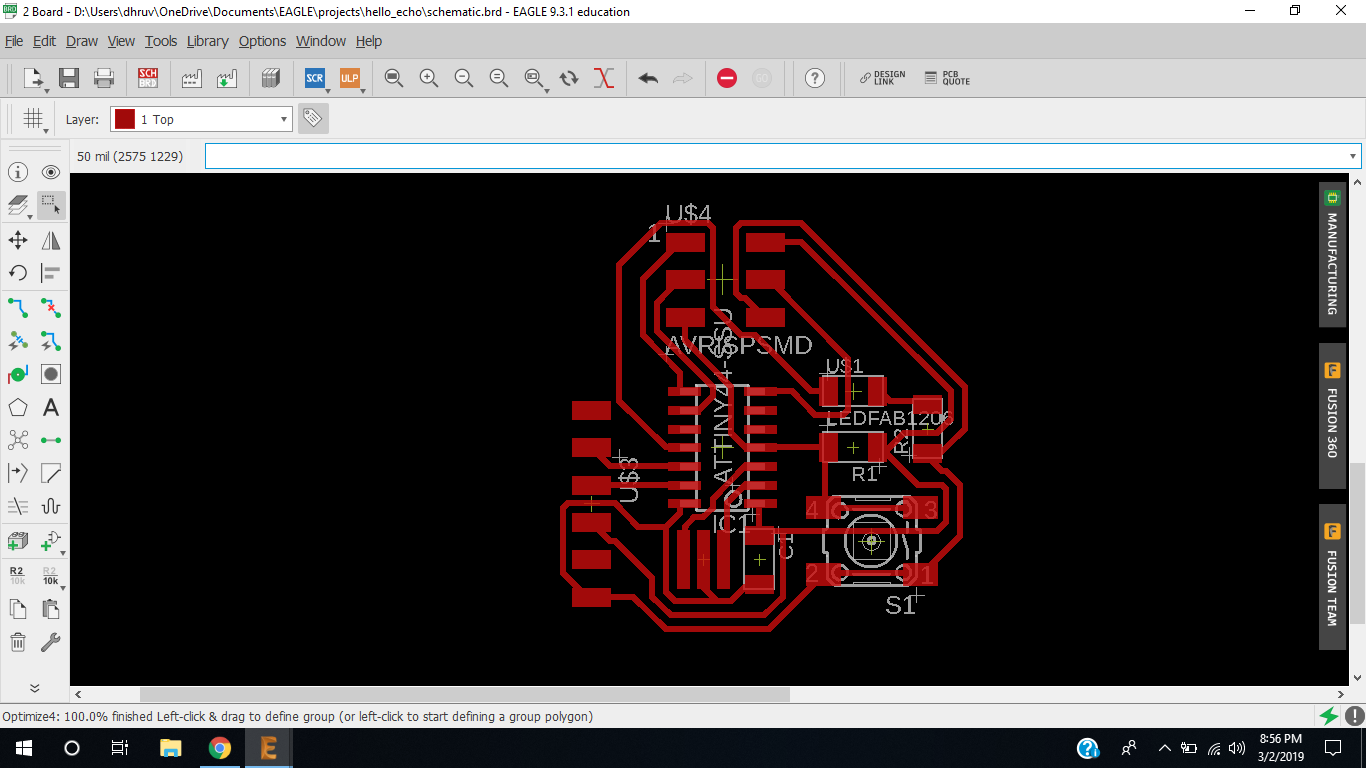
Final design
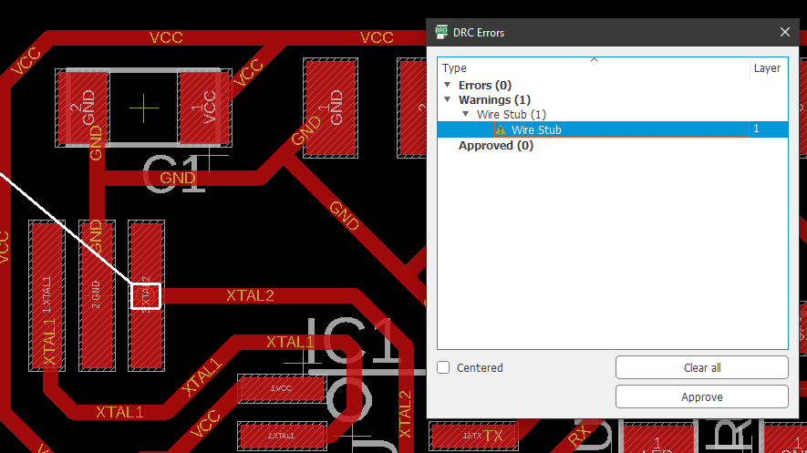
Error checks
On Check I had warnings of wire stud, Warning and errors are different things, when you get errors it will face some problems while PCB milling for sure, and when you get warnings it means you might face some issues while PCB milling, warnings have a relatively small weight, but it should be in consideration if you are new to PCB milling.
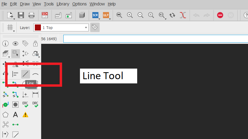
Create border of circuit
we have to create a border of the circuit to define the boundary of the circuit, it also defines how your circuit will look, You can use the line tool to create a border.
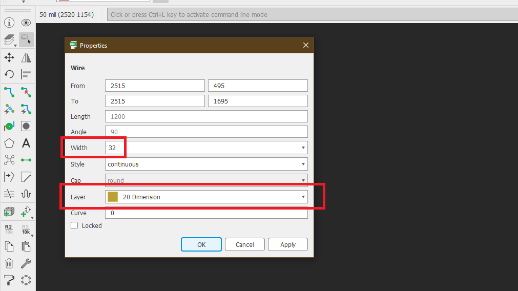
Properties menu
Right-click on the lines and go to Properties and change the Width and Layer(Change layer only if you want a border in a different layer), Here I Don't.
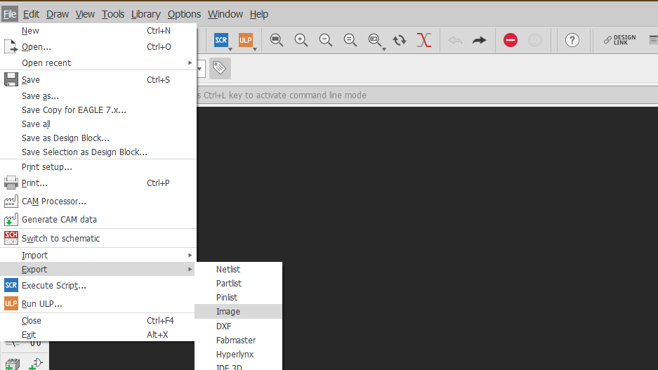
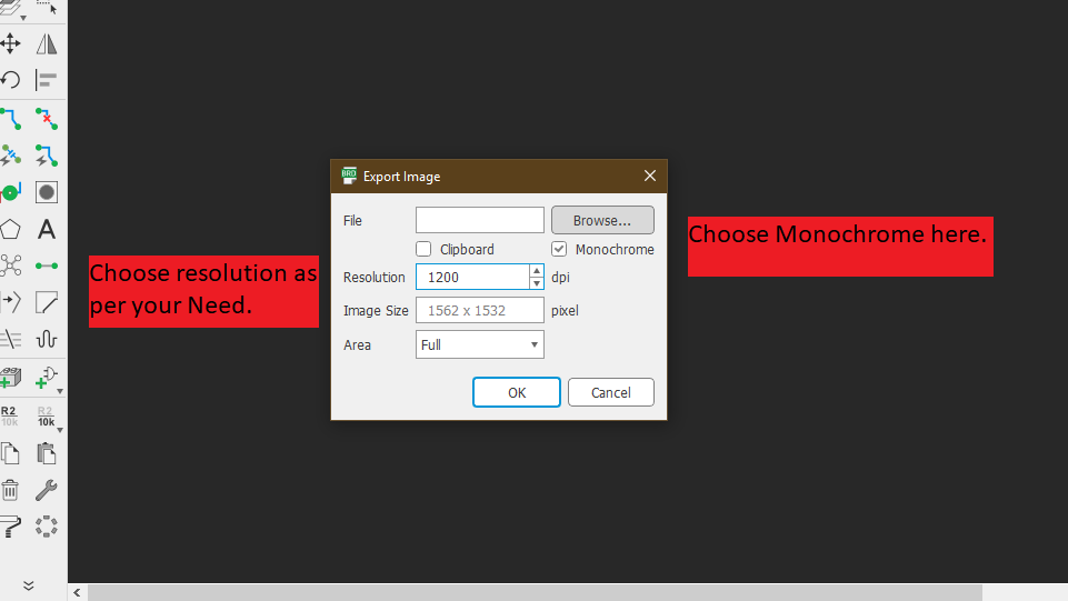
Exporting image in monochrome
Go to File > Export > Image
Choose monochrome and Give resolution you want.
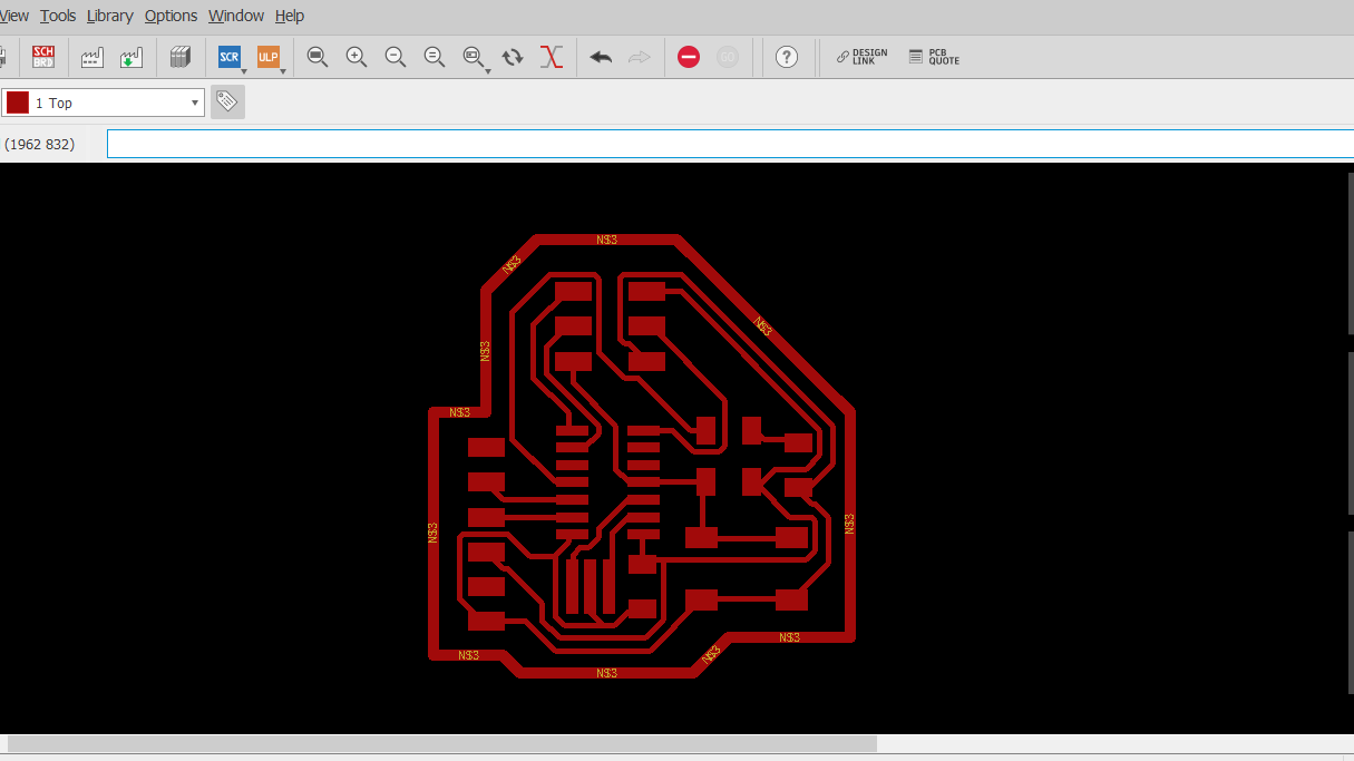
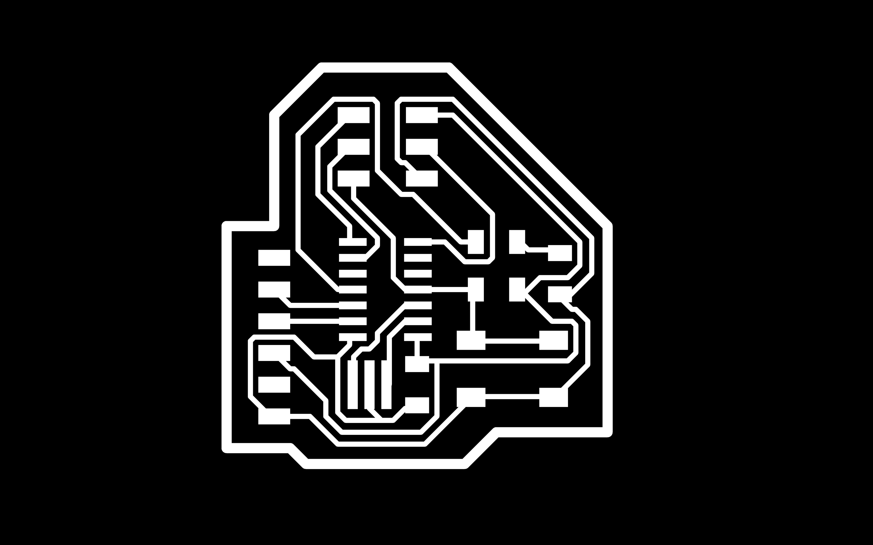
Final output
Every Trace and Border will be converted into White Color and the background will be converted into black. Remember To delete that Yellow rectangle border which comes Default. Otherwise your trace file and cut file dimensions will increase after editing in photoshop.
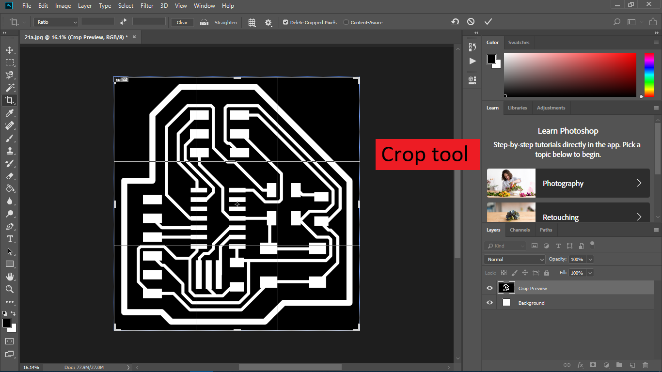
Photoshop
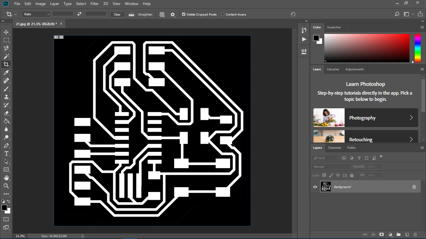
Crop the image. Remember to crop first and don't separate the trace file and cut file.
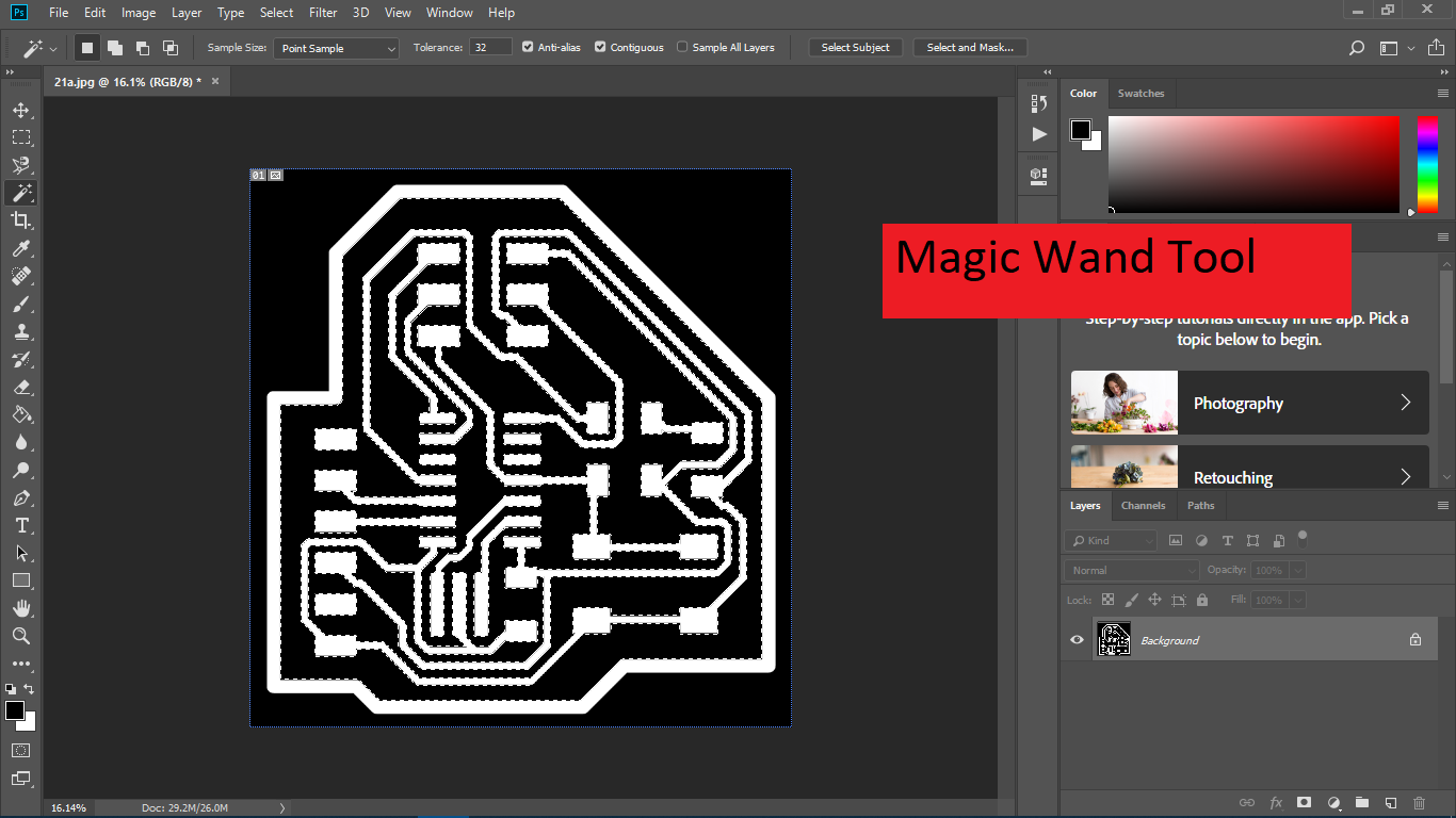
Select the traces with the Magic wand tool.
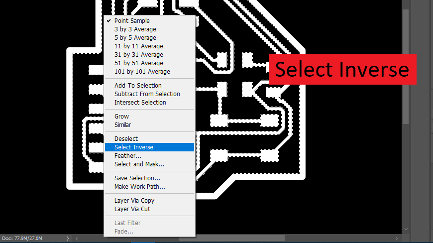
Inverse the selection
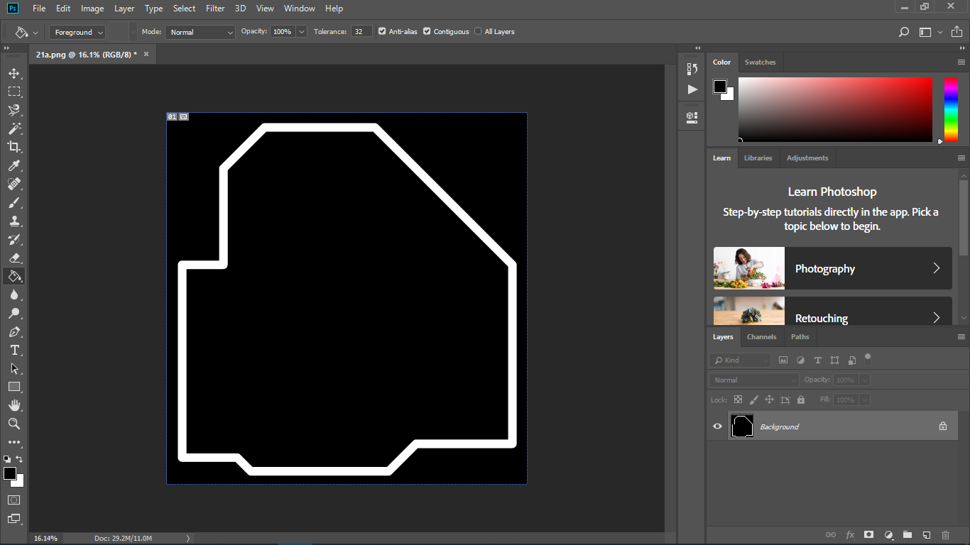
Use bucket tool to color the cut border
Do the same for generate Cut border
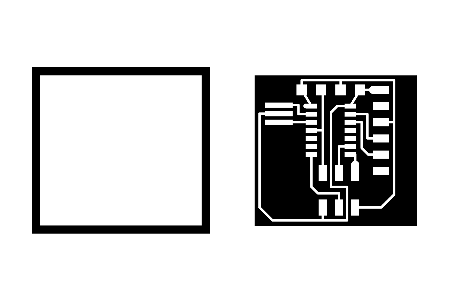
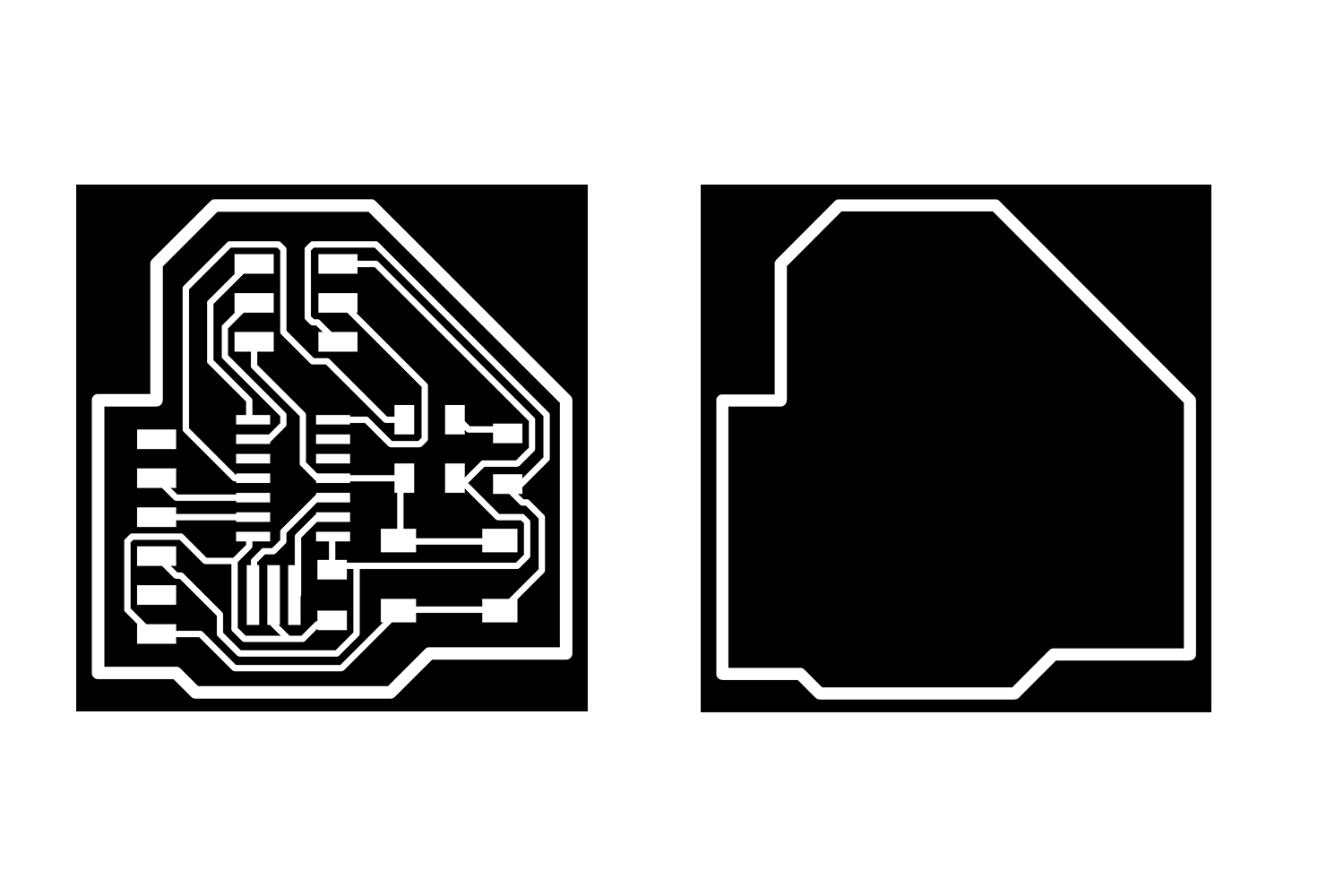
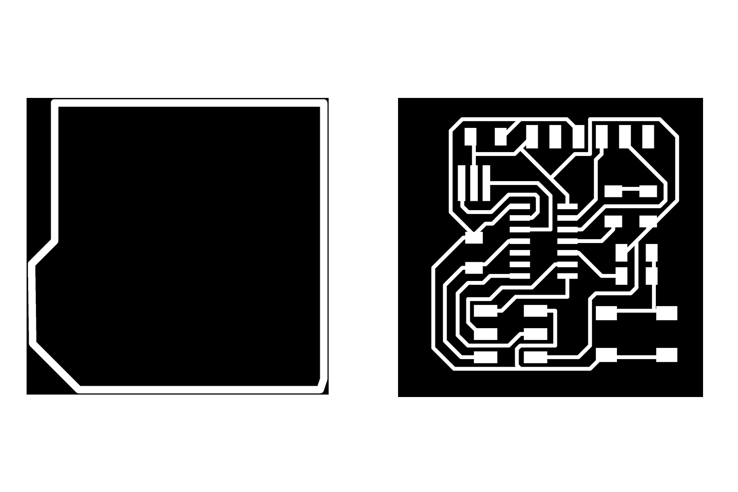
Cut and Trace Files
Click to get the Trace file and Cut file
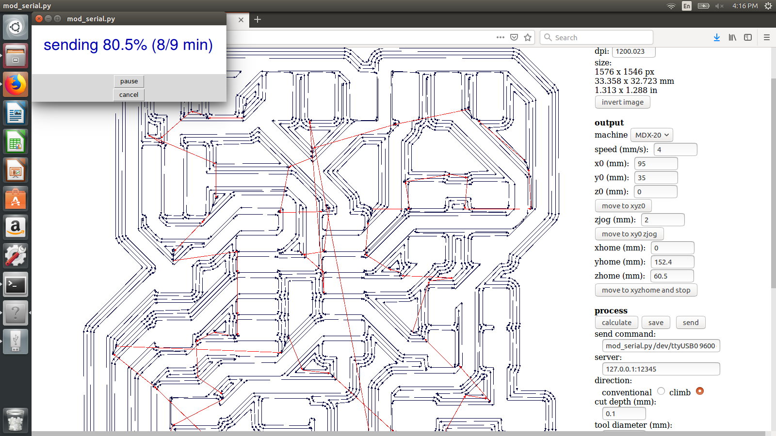
Milling
Click Here to Know procedure in the Roland MDX-20 Milling machine.
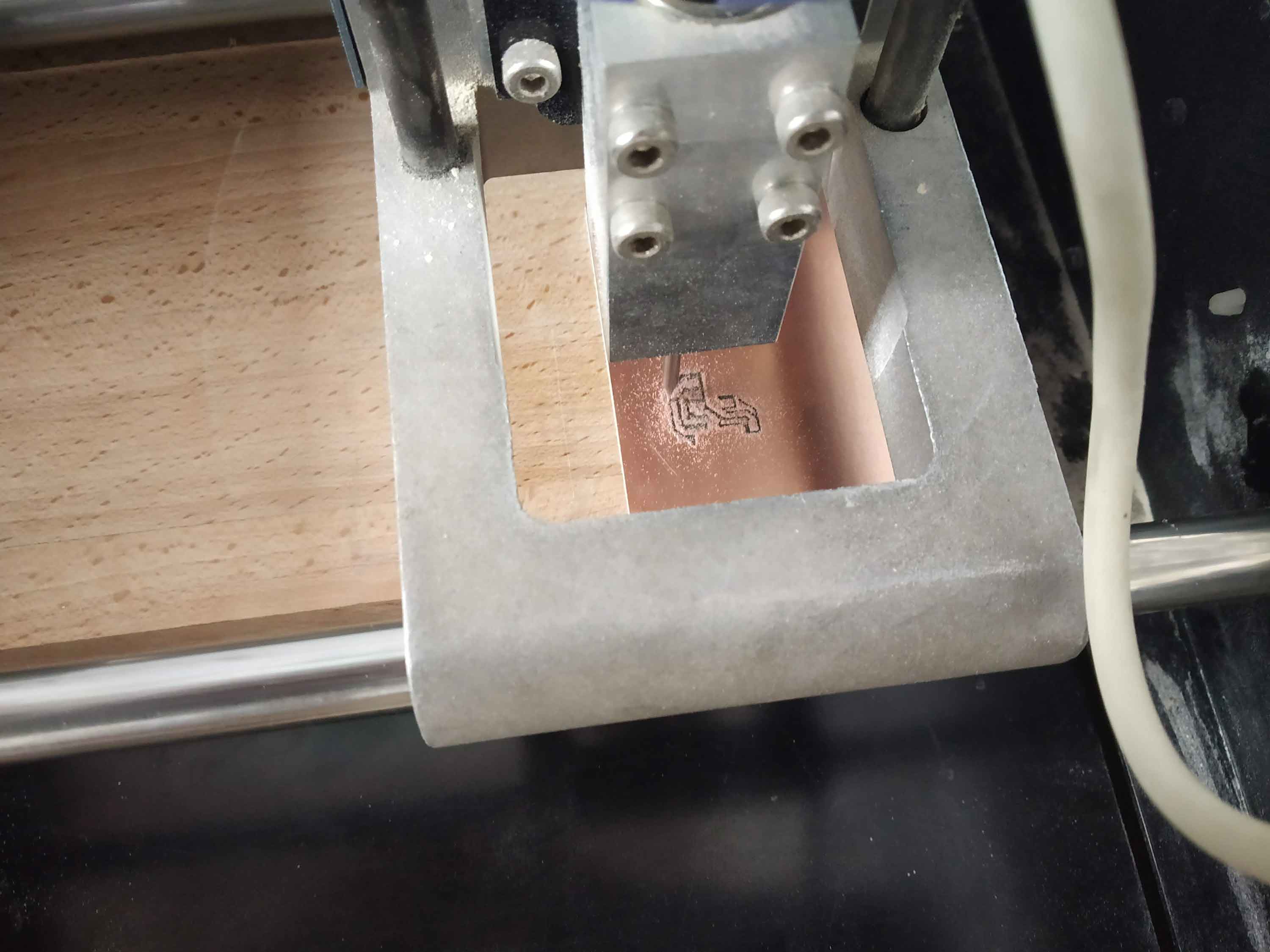
Trace part
Cut part
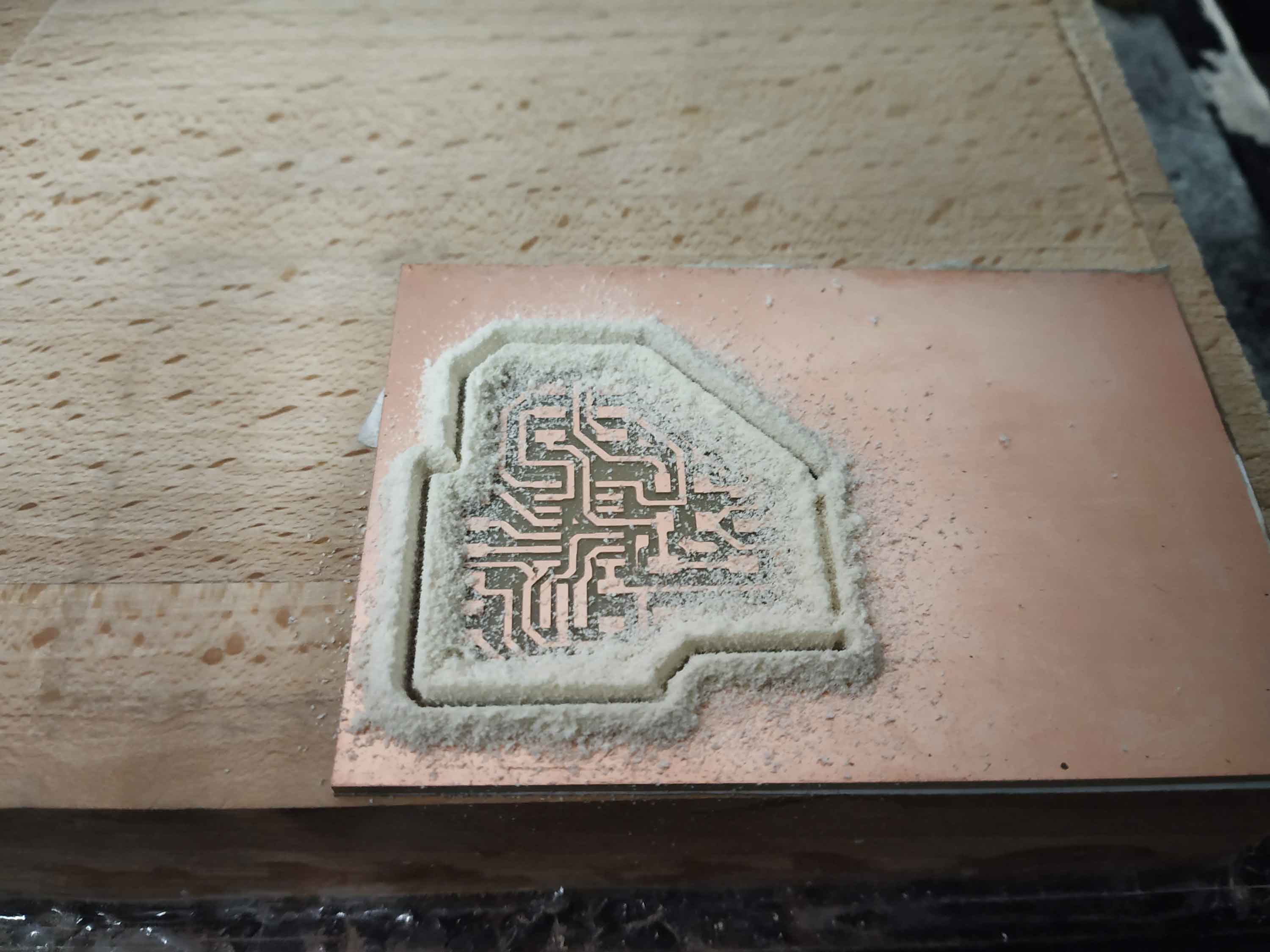
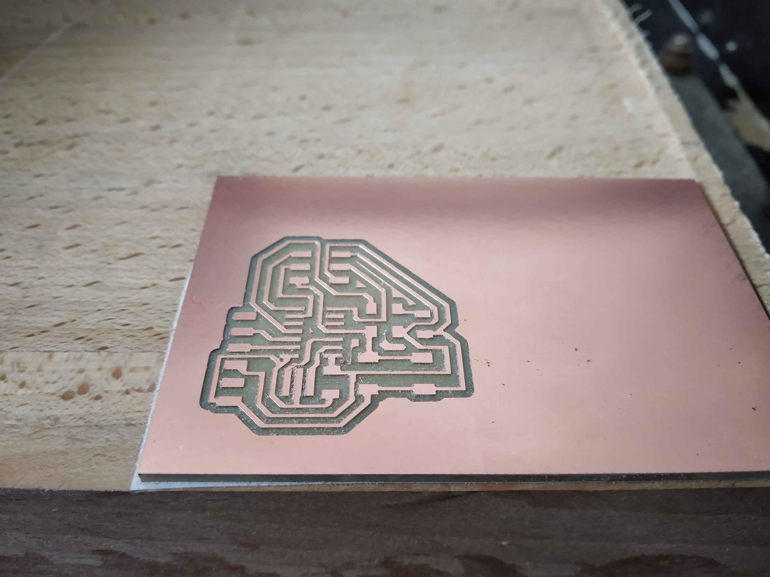
Output
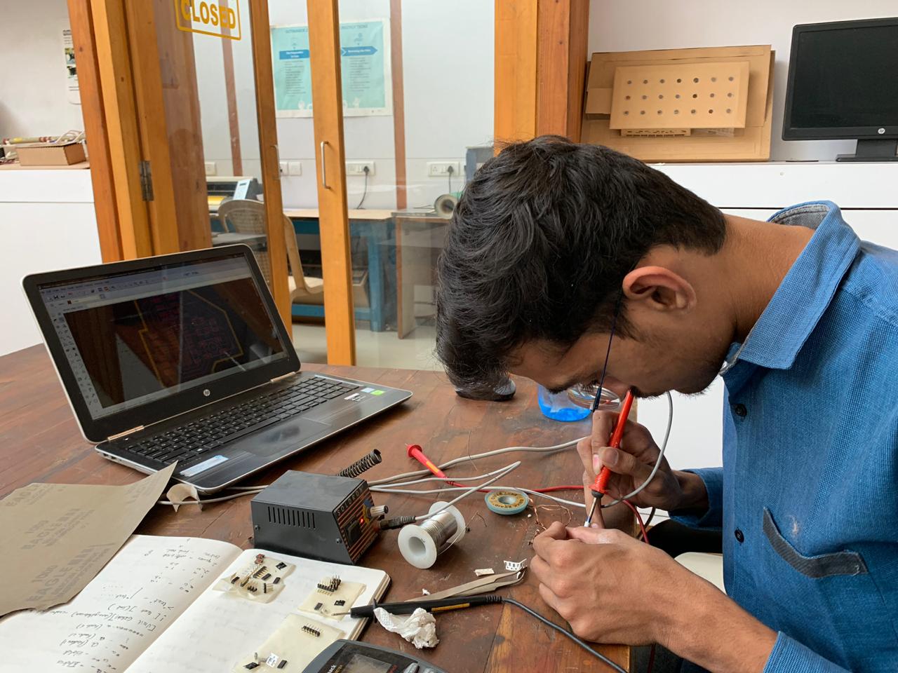
Soldering
Link for soldering basics, Week5.
Final Output
Accidently I touched the soldering iron on the button, That's why it looks weird.
This is The whole Procedure I explained, As I already mentioned on top I had a problem with the Schematic, I have to redesign the
board, but the procedure is the same.
Redesigning the Schematic
schematic of new board
This is the new schematic of my Echo hello board. I made a few changes here.
Switch Module- the switch is directly connected to power(VCC) and it is connected to R3 and R4 Pin swt will be low unless I will not press the switch.
R4 is connected to the microcontroller's pin which is named SWT(Switch) and R3 is connected to the ground.
You can download the original schematic from the link HERE and Board from Here.
You can download original Board diagram from link HERE.
Download Trace file and Cut File.
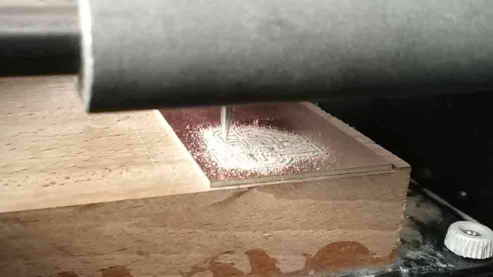
On Milling machine
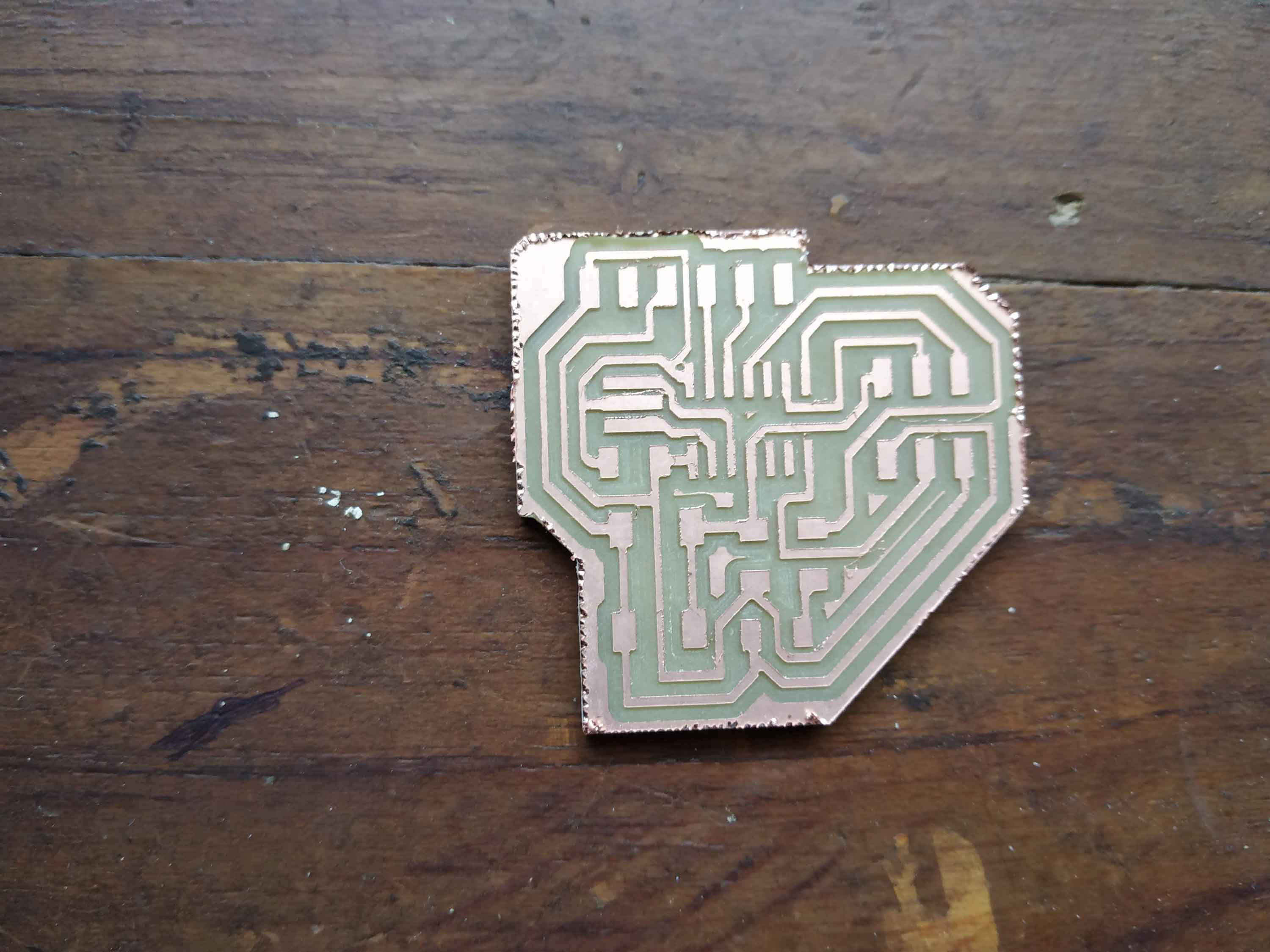
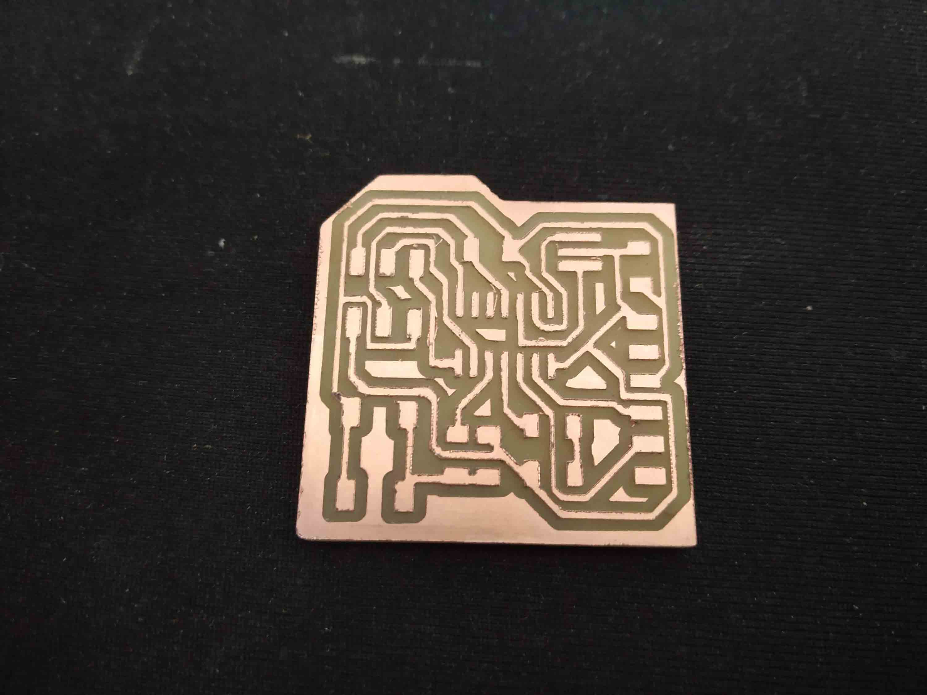
Output
traces are not that fine, copper was sticking with Bit. but somehow after Sanding, I start for soldering.
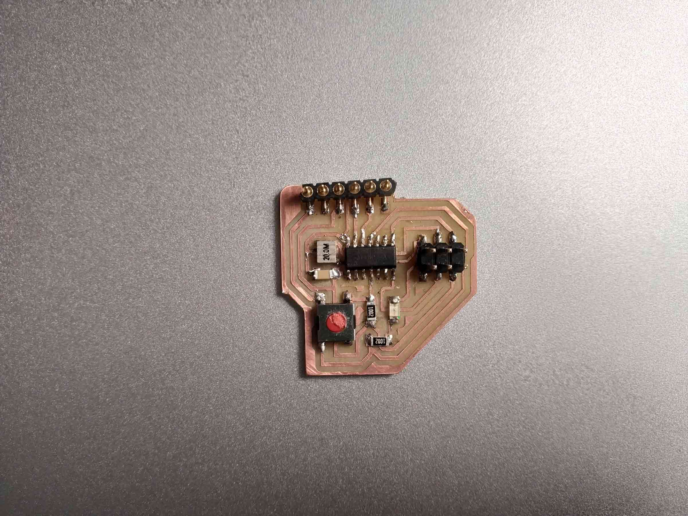
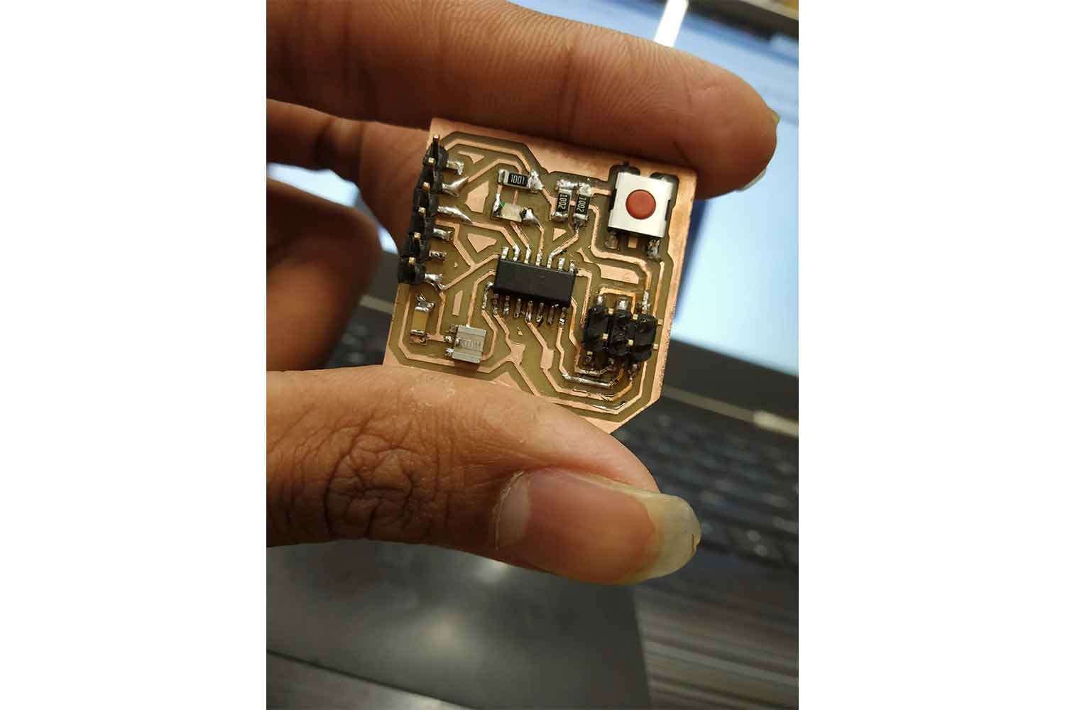
Soldering Output
Programming Board
I am going to program the echo hello board. there was a missing resister in echo hello in my design, I noticed it later, it was connected between Vcc and reset pin, will not affect working anyway.
Arduino tiny core
you have to paste
"http://drazzy.com/package_drazzy.com_index.json"on the additional board manager section.

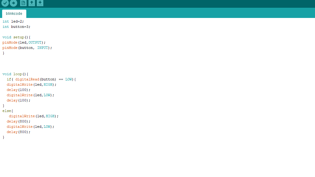
Controlling the blink of Led
To see the Microcontroller's action on the LED I Decided to make one relation between the Switch and the LED.
Code with the Switch. Since I put the Switch to the PA3(Arduino pin 3) and LED to the PA2(Arduino pin 2) in general I have written a code that tells the microcontroller to control the led blinking when I am pushing the button. Code link. here I am giving power
throught the FTDI.
I wrote the code to tell the microcontroller that if the Switch pin is low then let led blink faster, and if the switch pin is High then slow the blink rate of led, I am controlling the blink with delay() function.
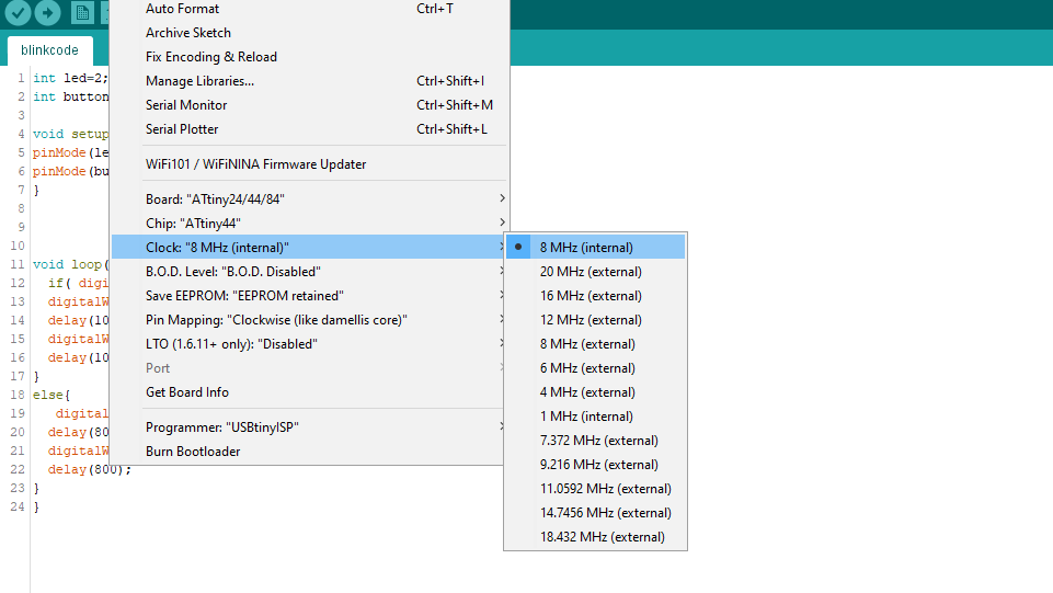
Give this settings.
Board: Attiny24/44/84
Chip: Attiny44
Clock: 8 Mhz here I am taking 8 Mhz because as a programmer I am going to use USBTinyisp.
Programmer : USBTinyisp, check week 5 to know more about FABtinyisp.
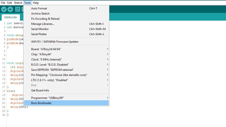
Then burn the bootloader
Burning the bootloader will set the fuses to the Microcontroller, it will set the Clock rate on the input and output pin. it will also allow you to upload the program using the FTDI - TTL converter you will not need a programmer after burning the bootloader once. Click here to know more.
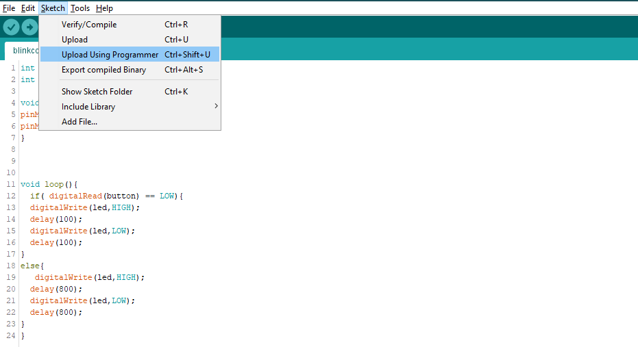
upload the sketch
Then Go to Sketch > upload using Programmer
Working PCB
Group work
In Electronic Design, group work is to use the different test equipment in our lab to observe the operations of microcontroller in the Circuit board.
we have
in group work there are not much more tasks that can be divided so we did it together, I get to learn Oscilloscope in group work, how can I use it to get a perfect delay between the data transmission. we did that on Neils Bigbanging code. everything is written in detail in the group web-site.
Conclusion
Electronics weeks are totally focused on learning new things and understanding weird names though, Still, I am getting used to it. What I learned this week is the only way to learn electronics is to do it over and over again. Here failure of the circuit is a normal thing, It doesn't matter how many time you give to orient the board diagram and design the schematic if the led didn't blink or the microcontroller got hot after plugin you probably messed up something and you are lucky if you got to know what is wrong with your circuit. Still, the week was Great.