Week 9 : Assignment
- Study Datasheet of microcontroller
- Program board with as many langauge as possible
This week we are going to learn about microcontrollers and embedded programming, our assignment was to understand the microcontroller by reading its Datasheet, to know different terms in micro controller and use them effectively in future to make own board in future as well. I want to start with very bottom , since I had some imformation about Electrical components in week 5. I started with terms like integrated circuits and microcontrollers.
Integrated circuit
An integrated circuit (IC), sometimes called a chip or microchip, is a semiconductor wafer on which thousands or millions of tiny resistors, capacitors, and transistors are fabricated. An IC can function as an amplifier, oscillator, timer,
counter, computer memory, or microprocessor. A particular IC is categorized as either linear (analog) or digital, depending on its intended application.
There are two types of IC. Linear IC and Digital IC.
Linear IC
Linear ICs have continuously variable output (theoretically capable of attaining an infinite number of states) that depends on the input signal level. As the term implies, the output signal level is a linear function of the input signal
level. Ideally, when the instantaneous output is graphed against the instantaneous input, the plot appears as a straight line. Linear ICs are used as audio-frequency (AF) and radio-frequency (RF) amplifiers. The operational amplifier(op
amp)
is a common device in these applications.
Digital IC
Digital ICs operate at only a few defined levels or states, rather than over a continuous range of signal amplitudes. These devices are used in computers, computer networks, modems, and frequency counters. The fundamental building blocks of digital ICs are logic gates, which work with binary data, that is, signals that have only two different states, called low (logic 0) and high (logic 1).
microcontroller
It’s like a small computer on a single IC. It contains a processor core, ROM, RAM, and I/O pins dedicated to performing various tasks. Microcontrollers are generally used in projects and applications that require direct control of users. As it has all the components needed in its single chip, it does not need any external circuits to do its task so microcontrollers are heavily used in embedded systems and major microcontroller manufacturing companies are making them be used in the embedded market. A microcontroller can be called the heart of the embedded system. Some examples of popular microcontrollers are 8051, AVR, PIC series of microcontrollers.
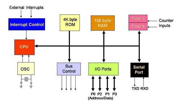
architecture of 8051 microcontroller
Below is the architecture of the 8051 microcontrollers. And you can see all the required components for a small project is present in a single chip.
Wiki definition
A Microcontroller (MCU for microcontroller unit, or UC for μ-controller) is a small computer on a single integrated circuit. In modern terminology, it is similar to but less sophisticated than, a system on a chip (SoC); an SoC may include a microcontroller as one of its components. A microcontroller contains one or more CPUs (processor cores) along with memory and programmable input/output peripherals. Program memory in the form of ferroelectric RAM, NOR flash, or OTP ROM is also often included on-chip, as well as a small amount of RAM. Microcontrollers are designed for embedded applications, in contrast to the microprocessors used in personal computers or other general-purpose applications consisting of various discrete chips.
Memory types
RAMRandom Access Memory (RAM) is a term commonly used to describe the memory within a computer. Unlike ROM, RAM is a volatile memory and requires power; if power is lost, all data is also lost.
Flash nor
Flash memory is an electronic (solid-state) non-volatile computer storage medium that can be electrically erased and reprogrammed.
OTP (One time programmable) ROM
A programmable read-only memory (PROM) is a form of digital memory where the setting of each bit is locked by a fuse or anti-fuse. It is one type of ROM (read-only memory). The data in them is permanent and cannot be changed. PROMs are used
in digital electronic devices to store permanent data, usually low-level programs such as firmware or microcode.
The key difference from a standard ROM is that the data is written into a ROM during manufacture, while with a PROM the data is programmed into them after manufacture.
Difference between Integrated Circuit and microcontroller
The microcontroller is a register-based clock-driven integrated circuit that reads data from input, performs actions based on the instruction written in the memory, and displays the results at o/p. the biggest difference between a microcontroller and a normal IC is that it can be programmed through software instructions to perform different tasks. while an IC for e.g, IC for not gate performs just one function (of inverting the signal) and needs to be assembled on a breadboard or PCB board every time it is being used. It doesn't have any memory elements.
Microprocessor
The Microprocessor is one type of simple electronic or computer device which stores and processes the data, not a desktop or computer hardware include one or a few Integrated Circuits. It is similar to a microcontroller but does not have any peripheral devices like RAM, ROM, etc. The task of microprocessors is dependent on the exterior circuits of peripherals. But there are not work for the specific task, but they are needed where the task is tough and complicated like games, software development, other applications that require high memory, and also where I/O are not mentioned. The Microprocessor is called the heart of a computer system. For example, of the best Microprocessor are I3, Pentium, and I5, etc..
Terms
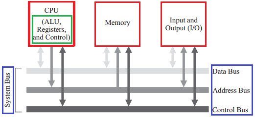
Bus (Computing)
In computer architecture, a bus (a contraction of the Latin omnibus) is a communication system that transfers data between components inside a computer, or between computers. This expression covers all related hardware components (wire,
optical fiber, etc.) and software, including communication protocols. Wiki.
A microprocessor is a processing device of every computing device. It is like an artificial brain. It needs to communicate with the outer world. for example, It needs to communicate with Input devices to get data, it needs to communicate
with memory to process data according to instructions written in memory and finally it needs to communicate with output devices to display the output on O/P devices. To communicate with the external world, the Microprocessor makes use of
buses. There are different types of buses used in Microprocessor.
Data bus
As name tells that it is used to transfer data within Microprocessor and Memory/Input or Output devices. It is bidirectional as Microprocessor requires to send or receive data. The data bus also works as address bus when multiplexed with
lower order address bus. Data bus is 8 Bits long. The word length of a processor depends on data bus, thats why Intel 8085 is called 8 bit Microprocessor because it have an 8 bit data bus.
Address bus
An address bus is a computer bus architecture. It is used to transfer data between devices. The devices are identified by the hardware address of the physical memory (the physical address). The address is stored in the form of binary
numbers to enable the data bus to access memory storage.
Control Bus
The microprocessor uses a control bus to process data, that is what to do with the selected memory location. Some control signals are Read, Write and Opcode fetch, etc. Various operations are performed by microprocessors with the help of a
control bus. This is a dedicated bus because all timing signals are generated according to the control signal.
ALU (Arithmetic logic unit)
An arithmetic logic unit (ALU) is a combinational digital electronic circuit that performs arithmetic and bitwise operations on integer binary numbers. This is in contrast to a floating-point unit (FPU), which operates on floating-point numbers. An ALU is a fundamental building block of many types of computing circuits, including the central processing unit (CPU) of computers, FPUs,
and graphics processing units (GPUs). A single CPU, FPU, or GPU may contain multiple ALUs. Wiki
Sorce
Datasheet
Important topics in the Datasheet
- features
- Block diagram
- Pin configuration
- Post information
- Graphical pinout
- Memory
- Power
- Registry summary
- Clock
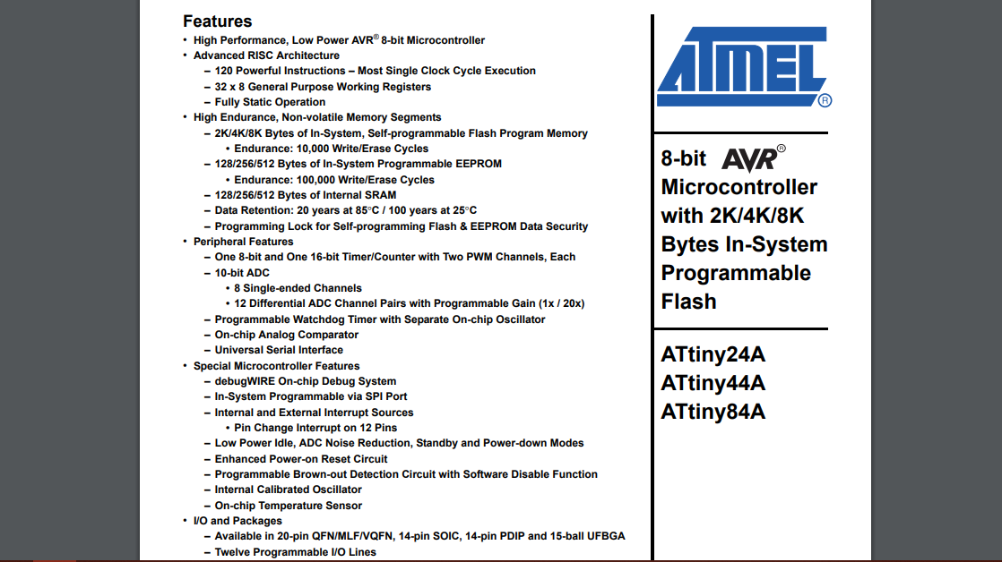
Features
The page is explaining about Key things about microcontroller, it is 8-bit microcontroller that means it can process 8 - a bit of word size per second. An 8-bit controller works on 8-bits at a time hence
suitable for low power, less compute-intensive application.
Data types matter in 8-bit. For example, int var_1 allocates 2 bytes in AVR ( 8-bit micro) and char var_2 allocates 1 byte.
Since I tell you it shows the processing ability of the microcontroller it
also
effects the ALU (Arithmetic Control Unit). An 8-bit microcontroller refers to the processing capability of ALU of a microcontroller.
Architectural overview
ATtiny44 has advance RISC architecture.
Reduced instruction set computer, or RISC (/rɪsk/), is one whose instruction set architecture (ISA) allows it to have fewer cycles per instruction (CPI) than a complex instruction set computer (CISC). Various suggestions have been made regarding a precise definition of RISC, but the general concept is that such a
computer has a small set of simple and general instructions, rather than a large set of complex and specialized instructions. Wiki.
Memory
Types of Memory in micro controller
- In-system re programmable memory
- EEPROM Data Memory
- SRAM Data Memory
- I/O Memory
In system re-programmable memory (Flash and EEROM)
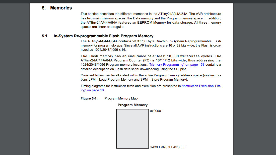
The ATtiny24A/44A/84A contains 2K/4K/8K byte On-chip In-System Reprogrammable Flash memory for program storage. The Flash memory has an endurance of at least 10,000 writes/erase cycles.
It means one can program the isp for 10,000 times approximately. after that microcontroller will not be sure to program. As I explained in the beginning flash memory no - volatile memory and it is the type of EEROM (electrically
erasable read-only memory) that has large storage space in comparison to EEROM. Though EERom has an advantage in programmable cycles, one can program 1,000,000 (cycles) times in EEROM type memory.
.
flash memory differs in a way that EEROM has only one transistor per bit. but flash has 8 transistors per
bit so it is much faster in writing large data over A EEROM and used for store the firmware code and EEROM are used to track history and parameters.
Static rendom Access memory
Static random-access memory (static RAM or SRAM) is a type of semiconductor memory that uses bistable latching circuitry (flip-flop) to store each bit. SRAM exhibits data remanence, but it is still volatile in the conventional sense
that
data is eventually lost when the memory is not powered.
The term static differentiates SRAM from DRAM (dynamic random-access memory) which must be periodically refreshed. SRAM is faster and more expensive than DRAM; it is typically used for CPU cache while DRAM is used for a computer's main
memory. Wiki
Dynamic rendom access memory
Dynamic random-access memory (DRAM) is a type of random-access semiconductor memory that stores each bit of data in a separate tiny capacitor within an integrated circuit. The capacitor can either be charged or discharged; these two
states are taken to represent the two values of a bit, conventionally called 0 and 1.
The electric charge on the capacitors slowly leaks off, so without intervention, the data on the chip would soon be lost. To prevent this, DRAM requires an external memory refresh circuit which periodically rewrites the data in the
capacitors, restoring them to their original charge.
This refresh process is the defining characteristic of dynamic random-access memory, in contrast to static random-access memory (SRAM) which does not require data to be
refreshed.
Unlike flash memory, DRAM is volatile memory (vs. non-volatile memory), since it loses its data quickly when power is removed. However, DRAM does exhibit limited data remanence.
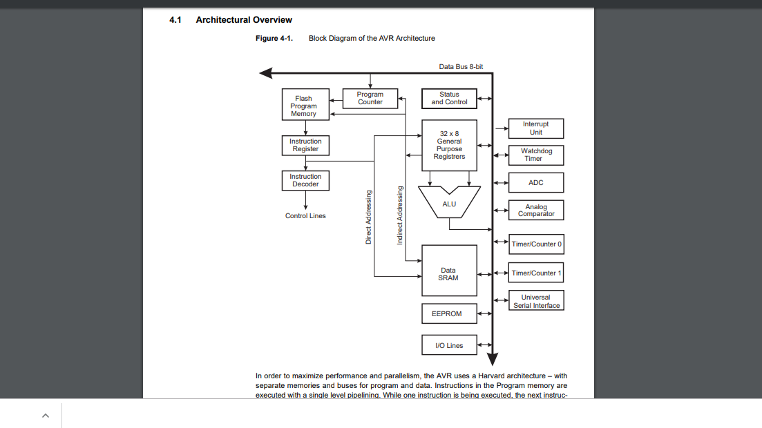
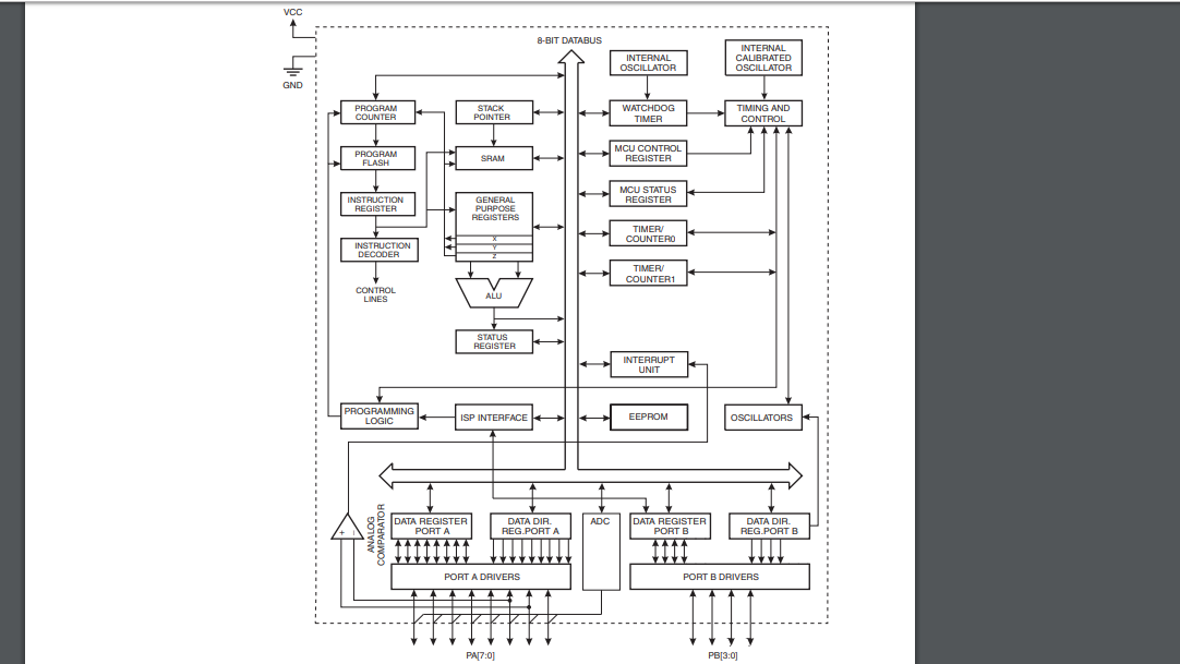
Block diagram
In learning the first thing I noticed it everything is connected to one single line or path called 8-bit Bus. I am still not fully aware of the design here but I can say all the microcontroller controlling units(which help
microcontroller to synchronize on every clock signal) are on the right side of the 8-bit bus. On the left side of the bus Processing unit including the Memmory portion, Register, Logic unit(ALU)
is
placed.
I will write about this in the clock signal part. But I can tell this clock works come to the Timer Counter.Here WATCHDOG TIMER creates automatically system reset when it hangs if the main program neglects to
periodically service it.
INTERNAL Calibrated CLOCK is an internal clock of micro-controller in microcontroller ATtiny44 its maximum frequency is 8Mhz.
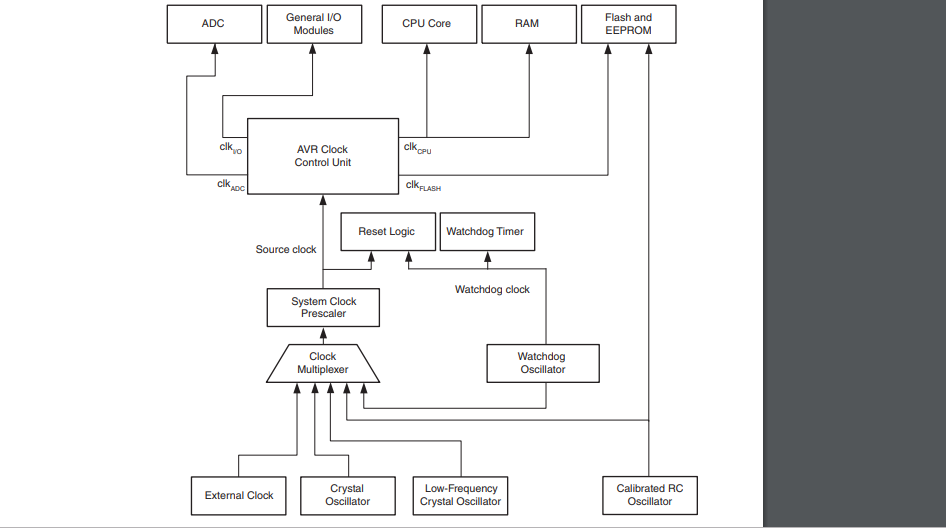
Clock
This section is trying to explain the clock system of the ATTiny44.
A clock signal or pulse is used in digital circuits of sequential circuits for differentiating output with time. As in sequential circuits output, is fed back to the input, and new output will be given after every clock pulse.
Applications flip flops, 555 timer, etc.
Clock is used in digital circuit for the following reasons:
- To synchroze the digital circuit.
- To produce the proper interval between two inputs and outputs.
- To produce th delay and generating square wave.
timing is everything in Digital Circuits. Without clocks, digital circuits cannot run. Clocks control the input and output of the circuit and provide synchronization for peripherals. Most integrated circuits (ICs) of sufficient complexity
use a clock signal in order to synchronize different parts of the circuit, cycling at a rate slower than the worst-case internal propagation delays.
Propagation delay
In electronics, digital circuits, and digital electronics, the propagation delay, or gate delay, is the length of time which starts when the input to a logic gate becomes stable and valid to change, to the time that the output of that
logic gate is stable and valid to change.
Often on manufacturers' datasheets, this refers to the time required for the output to reach 50% of its final output level when the input changes to 50% of its final input level. Reducing gate delays in digital circuits allows
them to process data at a faster rate and improve overall performance. The determination of the propagation delay of a combined circuit requires identifying the longest path of propagation delays from input to output and by adding each
tpd time along this path. The Clock signal interval should always be more than the propagation delay.
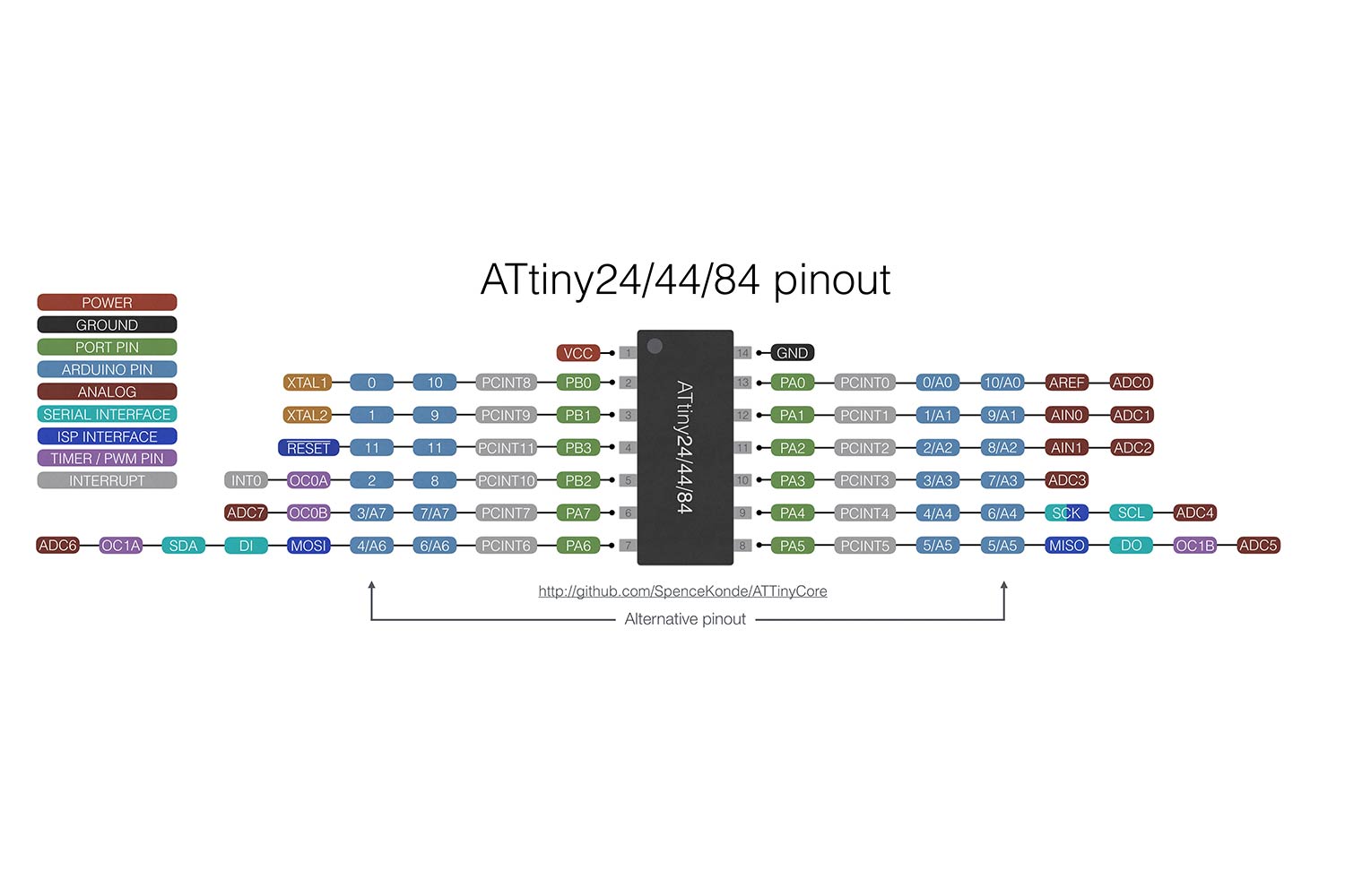
Pin configuration
- VCC- Voltage, common collector
- GND- Ground
- PCINT- I/O Pins
- XTAL- Crystal Oscillator
- RESET- Reset
- MOSI- Master Out Slave In
- MISO- Master In Slave Out
- OC- Timer
- ADC- Analog to Digital Converter
- SCK- Serial Clock
- AIN- Analog Comparator
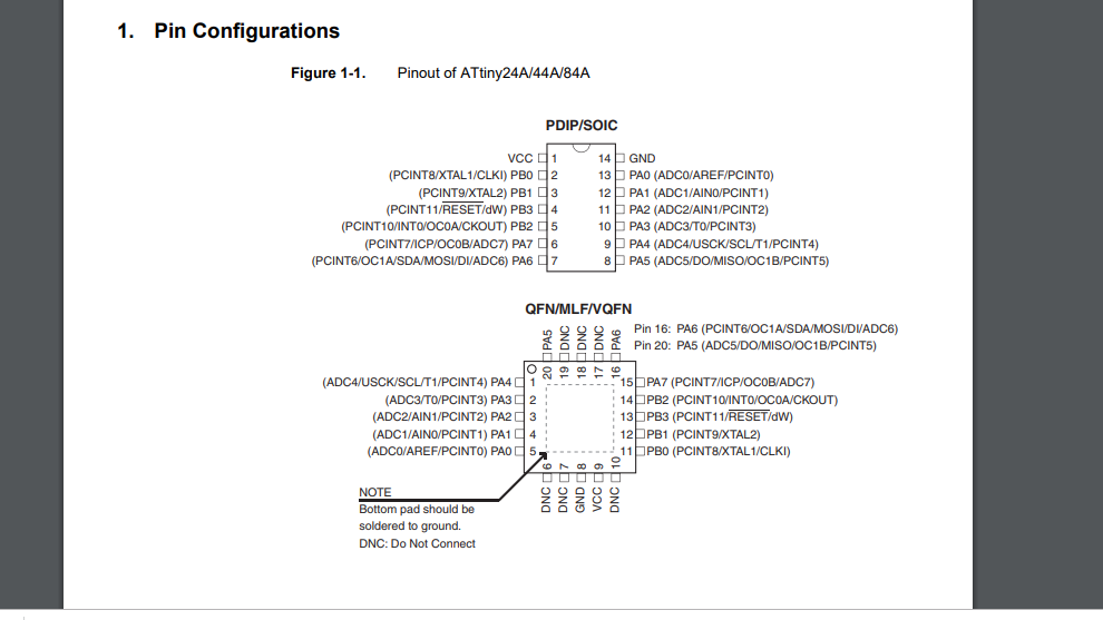
Graphical pinout
Graphical pinout helps to use the microcontroller more effectively, when you are using it with different development software you will need to give then specific pin number where you want to have some output or some input also, here for Arduino Development environment (IDE) blue pins shown in picture is are Arduino pins you can give specific inputs and output at pins in Arduino IDE which we will see soon in board programming. In week 7 I already talk about Attiny 44 pinout and Some terms in Details.
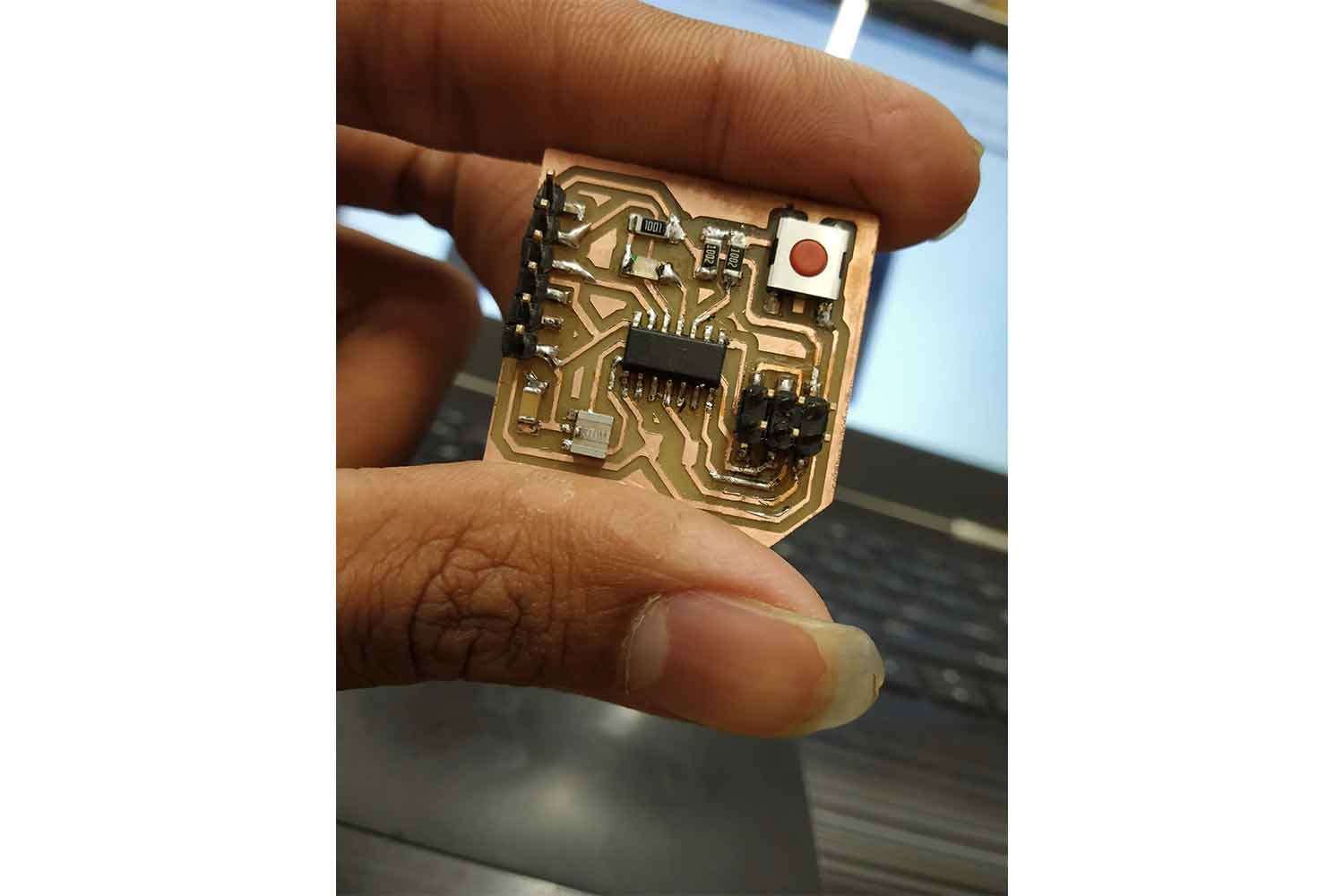
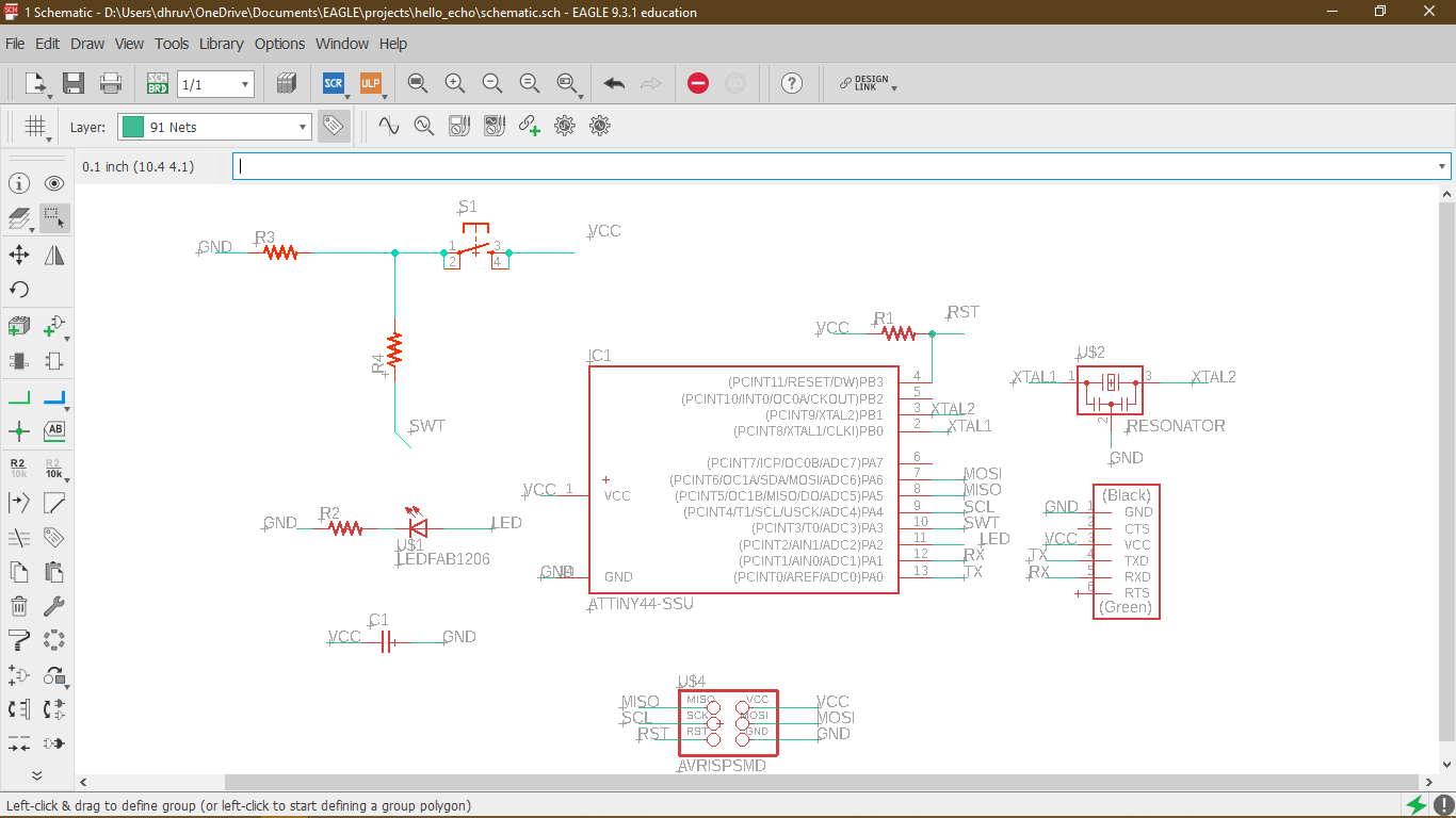
Programming Board
I am going to program the echo hello board. there was a missing resister in echo hello in my design, I noticed it later, it was connected between Vcc and reset pin, will not affect working anyway.
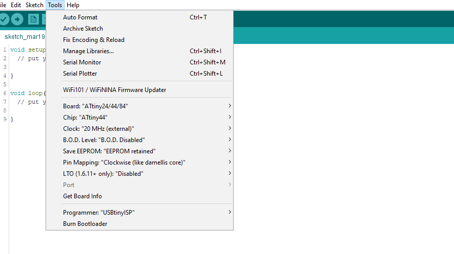
Programming in Arduino IDE
For programming Attiny 44 in Arduino ide, one has to include board settings to the ide, one can do that by adding some particular link in the Preference of file menu, see below!
Arduino tiny core
You have to paste
"http://drazzy.com/package_drazzy.com_index.json"on the additional board manager section.

settings in tools
Give this setting, you can visit week 5 for settings. Burn the bootloader.
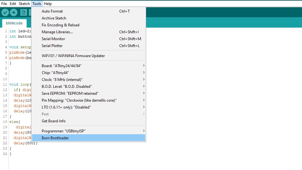
Blinking the Led
To see the Microcontroller's action on the LED I Decided to make one relation between the Switch and the LED.
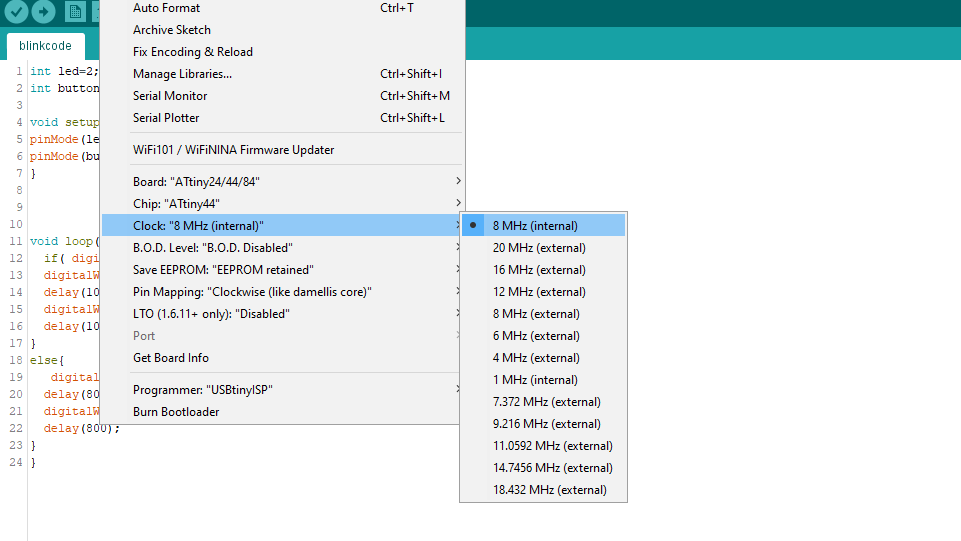
Code
Final code with the Switch. Since I put the Switch to the PA3(Arduino pin 3) and LED to the PA2(Arduino pin 2)
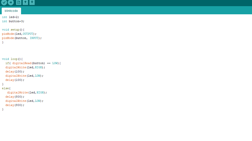
power from FTDI
in general, I have written a code that tells the microcontroller to control the led blinking when I am pushing the button. Code link. here I am giving power through the FTDI.
embedded programming work
One can fing other embedded programming work on week 11, week 12.
Group work
In Embedded programming, our group work was to compare the performance and development workflows for other architectures. we had stm32f103c8 Blue pill Development Board.
I generally know any other microcontrollers other that ATtiny and Atmega I was interested in the Datasheet part!
Specifications
- Name : stm32f103c8 Blue pill Development Board
- 72 MHz maximum frequency,1.25 DMIPS/MHz (Dhrystone 2.1) performance at 0 wait state memory access
- 64 or 128 Kbytes of Flash memory
- 4-to-16 MHz crystal oscillator
- Internal 40 kHz RC
- 7 timers
- Up to 9 communication interfaces : Up to 2 x I2C interfaces (SMBus/PMBus) , Up to 3 USARTs (ISO 7816 interface, LIN, IrDA capability, modem control), Up to 2 SPIs (18 Mbit/s).
visit group website for more imformation.
Conclusion
In three electronics weeks, this week was the first when I was getting something in mind about terminologies, I got time to explore about microcontroller though. I programmed simple code which Arduino IDE but I am also interested in learning other languages too, in meantime, I am going to try c programming to program my board.