Week 3 : Assignment
- model (raster, vector, 2D, 3D, render, animate, simulate, ...) a possible final project. and
- post final project on your class page
In week 3 we are introduced computer-aided design (CAD). CAD can be divided into 2 parts, 2d design, and 3d design. As per the name, 2d design is something like drawings we do on canvas and drafts which are made in engineering drawings. It's only based on 2 dimensions. In CAD we do 2d drawings in computers. 3d design is one step ahead, it’s the use of computers to make the 3-dimensional prototypes. We can use those models to ideation and prototyping(simulation).
We are introduced to many cad tools and told each software has its unique requirements, and this software would be more helpful in their respective field, and in whuch part they are better than
any others.
They are numbers of 2d and 3d design but I want to choose software that is new to me (based on the method of operating). I also wanted to research on some key ideas about 3d design which are Generative design concept and
script-based cad software (software which uses scripting instead of different features to do different operations).
generative Design
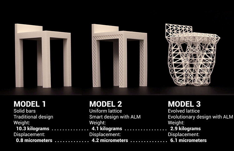
Generative design is a research area in CAD which helps the designer to ideate in a better way, it takes the information of a prototype like load constraints, and operating conditions and presents different models which can satisfy requirements. you can get more information here. Generative design is a research area in CAD which helps the designer to ideate in a better way, it takes the information of a prototype like load constraints, and operating conditions and presents different models which can satisfy requirements. you can get more information here.
Concept of generative design from webpage
Script-based cad software
Script-based cad software is very fast when you have to so the number of jobs in very less amount of time, traditional (history-based) software is very efficient for this type of job because they work on a history tree and take more re-computation time.
References and study for Week 3
This are the articles you may like read to know better in areas of CAD:
Tools I learned This week
- Inkscape - 2d vector software
- Photoshop – raster
- Fusion-360 - Student version For 3d modeling
- Autocad – Autocad student version
Inkscape
I started exploring in week 3 with Inkscape. It is open-source software for vector design. It is good for illustrations, graphic design, logo design, and much more. i chose inscape because I wanted to do some work related to logo-design.
Objective
We are going to make beautiful logo done by logos by nick on youtube.
STEP 1 : MAking polygonal
First, make polygonal by polygonal tool and a select number of sides 6 for Hexagonal.
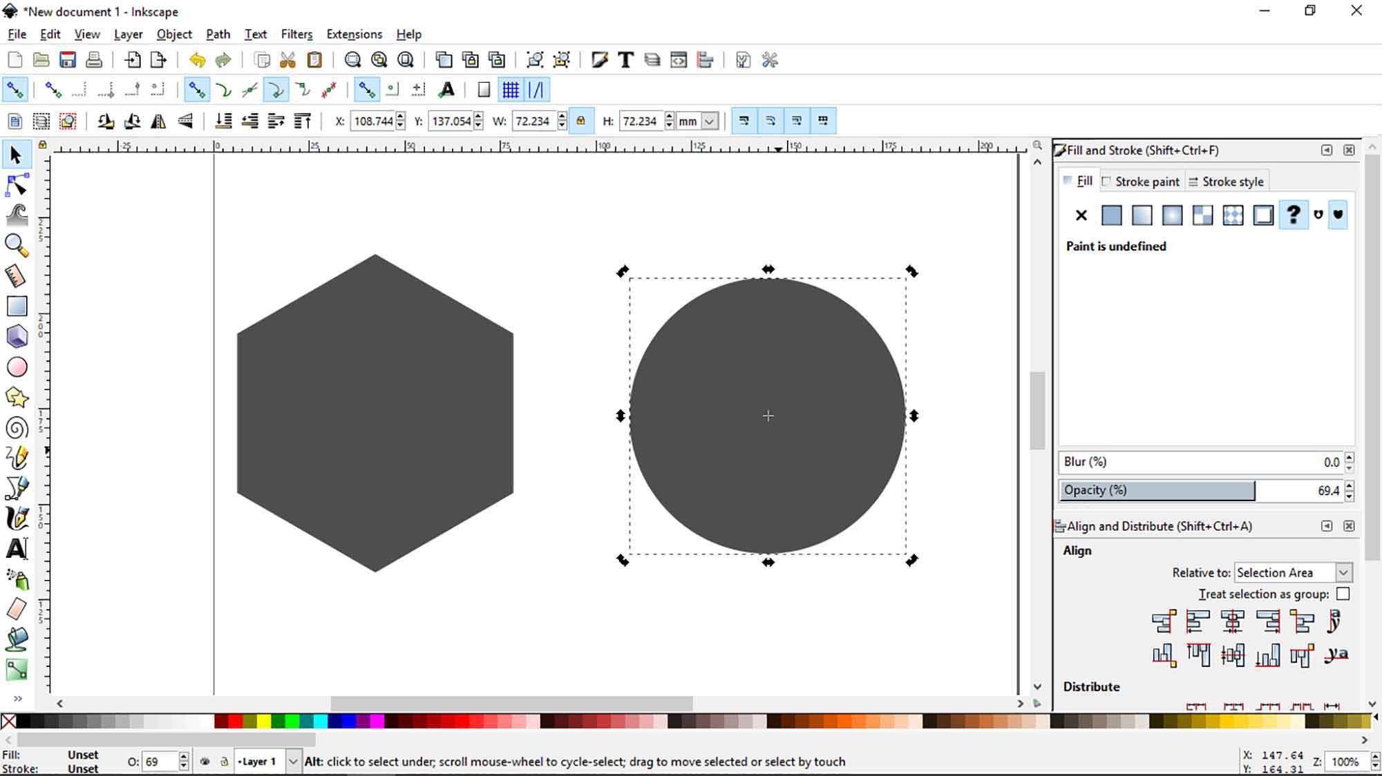
STEP 2 : Making and aligning circle
Now copy the width of polygonal! lock them by the icon shown in the figure. it will maintain the dimension ratio. Now make a circle, press CTRL + SHIFT for a perfect circle, then paste the
dimensions of circle's.
Change its color with color plates below.
Now select circle, press SHIFT, and select hexagonal then click vertical-align and horizontal-align tool at sides to make them align at both symmetries of an axis.

STEP 3 : How to substract sketches
Select circle, click path > Duplicate (it will generate  new circle).

Select circle, click path > difference (it will create difference between circle and polygonal).

Select circle, click path > break apart (it will separate entity).

Then go to Path > union (after SHIFT selecting both), colors will become same, in union sketches merges and become one sketch itself.
STEP 4 : How to Clean dots
( optional : if you are getting those dots! just re-select sketch and go to path > break apart, it should work)
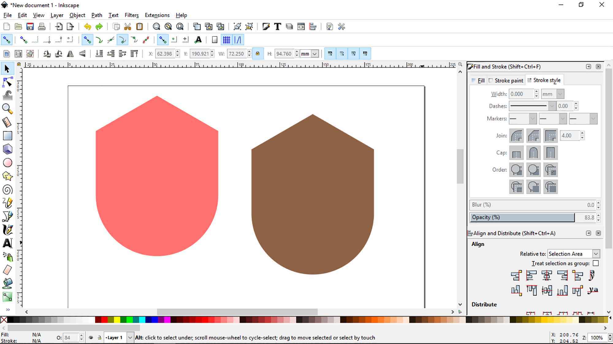
STEP 5 : how to convert strokes to path
Align both horizontal and vertically.

click brown polygonal and click lower selection to bottom. it will move the brown polygonal to lowest level.
In this process brown polygonal should remain selected.

now click one color at below. Repeat the same process and give it different color.
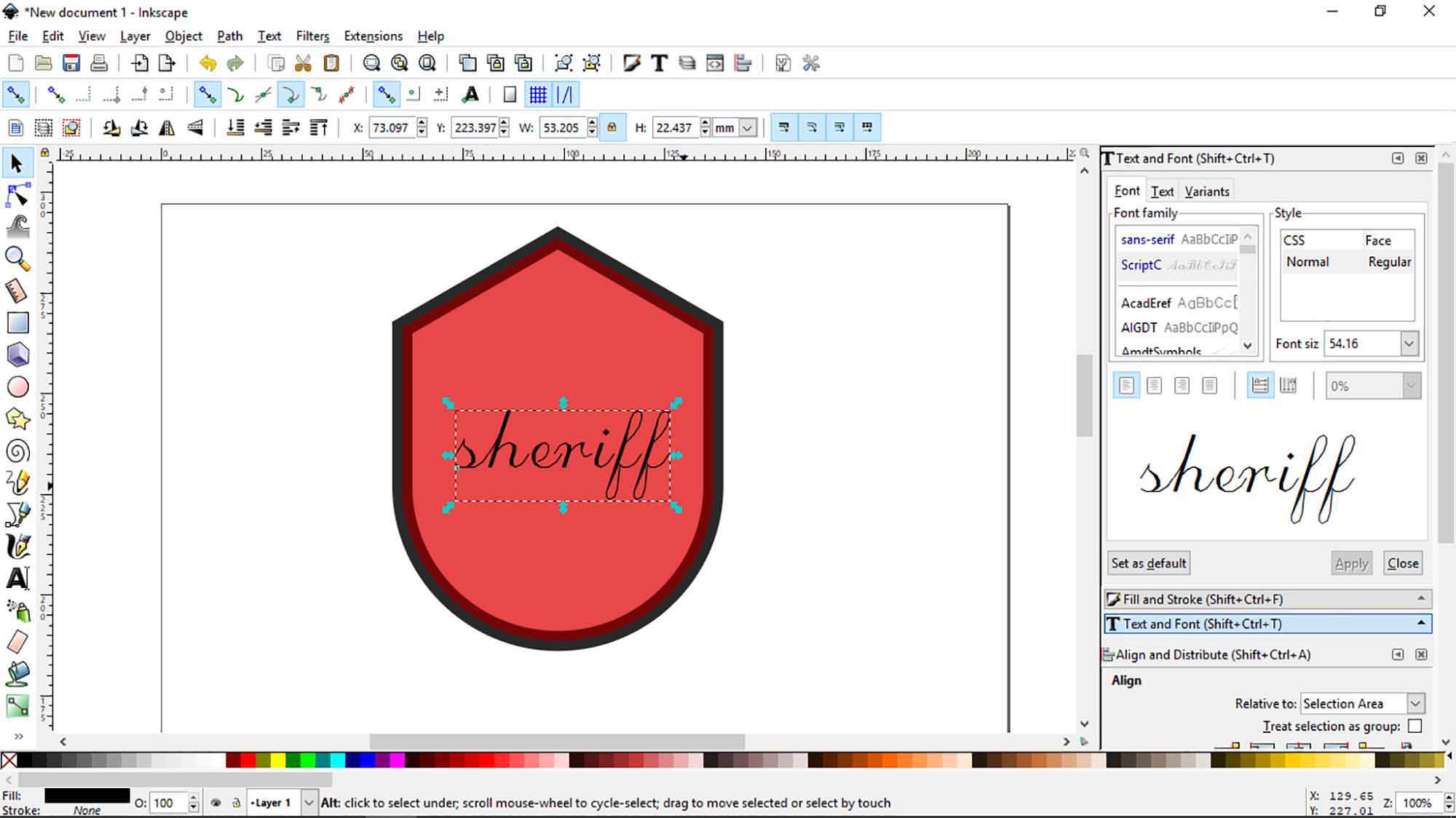
STEP 6 : Put a name on logo
Write something.

Edit it! give uniform scale by hold SHIFT and CTRL.

Choose rectangle. change opacity and align it with text. Move it downward by scaling tool.
STEP 7: Tracing image
Import images for logo.

Convert in vector by convert to bitmap. These settings will work, if no try 5,6 colors. Our bull is ready! Blue one is vector. you can put this images on logo.
STEP 8: give some background at photoshop
Here i used Photoshop for presenting. if you want it on good quality i will suggest you to open svg format to photoshop and then convert it on .jpeg

Final
Click to get file in : SVG PSD JPG

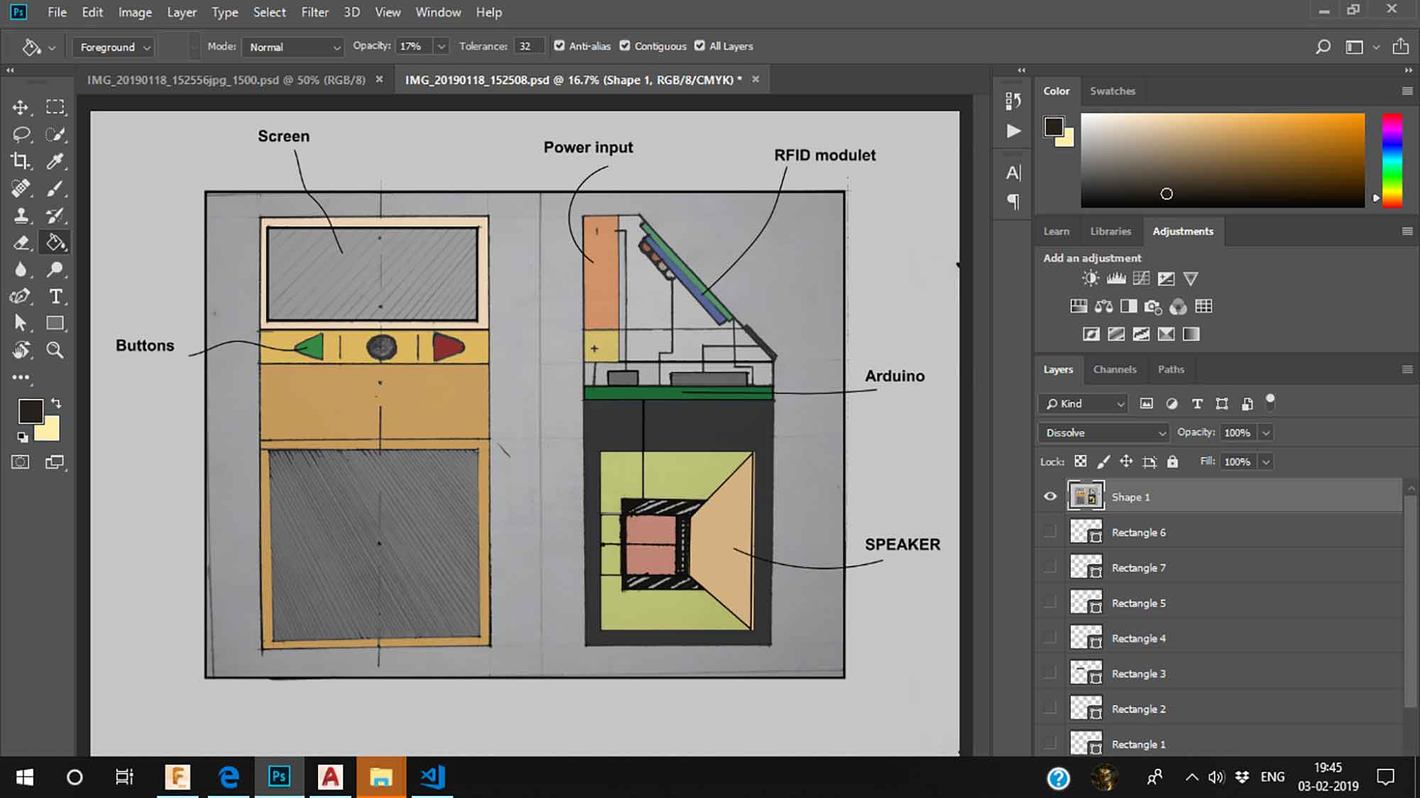
Raster Work on The Photoshop
Sometimes we need to edit over Sketches or edit different types of images, then we can use Photoshop software. Photoshop software is for raster editing and illustrator can be used for illustrations and graphic work where dots are on mathematical relationships. The procedure is shown below!
STEP 1 : Importing image
Import image on the photoshop.press CTRL + j for new layer.
STEP 2 : using bucket tool
Click paint bucket for direct painting(it will be little inaccurate).
STEP 3:Adding different colors
Add more colors by bucket tool.
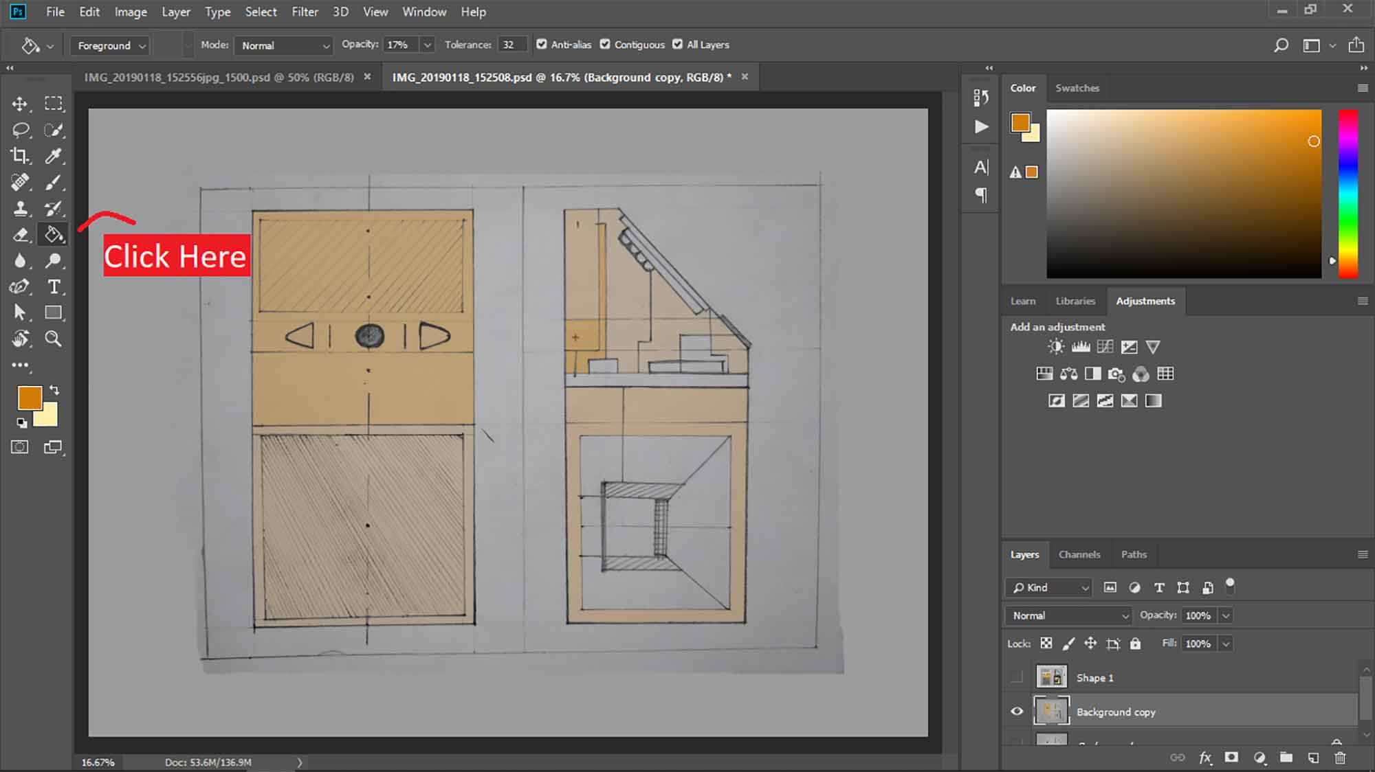
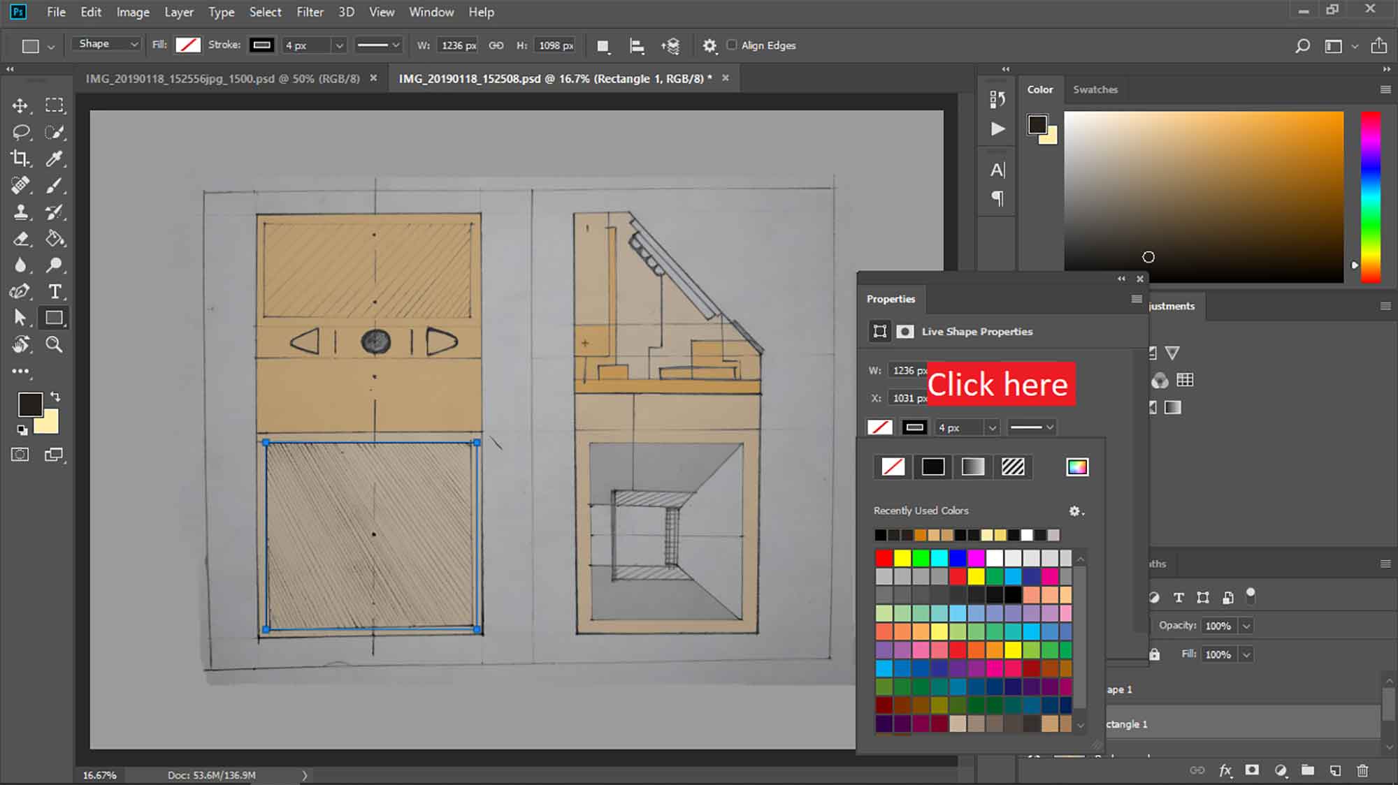
STEP 4 : rectangular tool
Select Rectangular tool from panel. With rectangular tool color will not go outer of border.
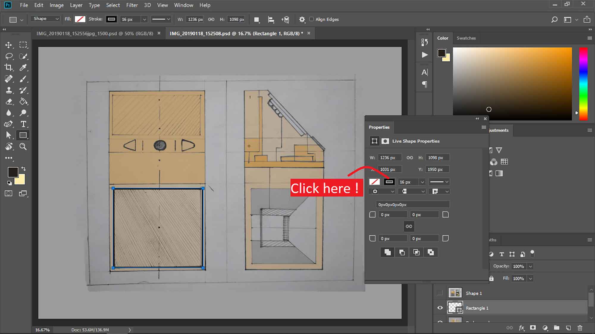
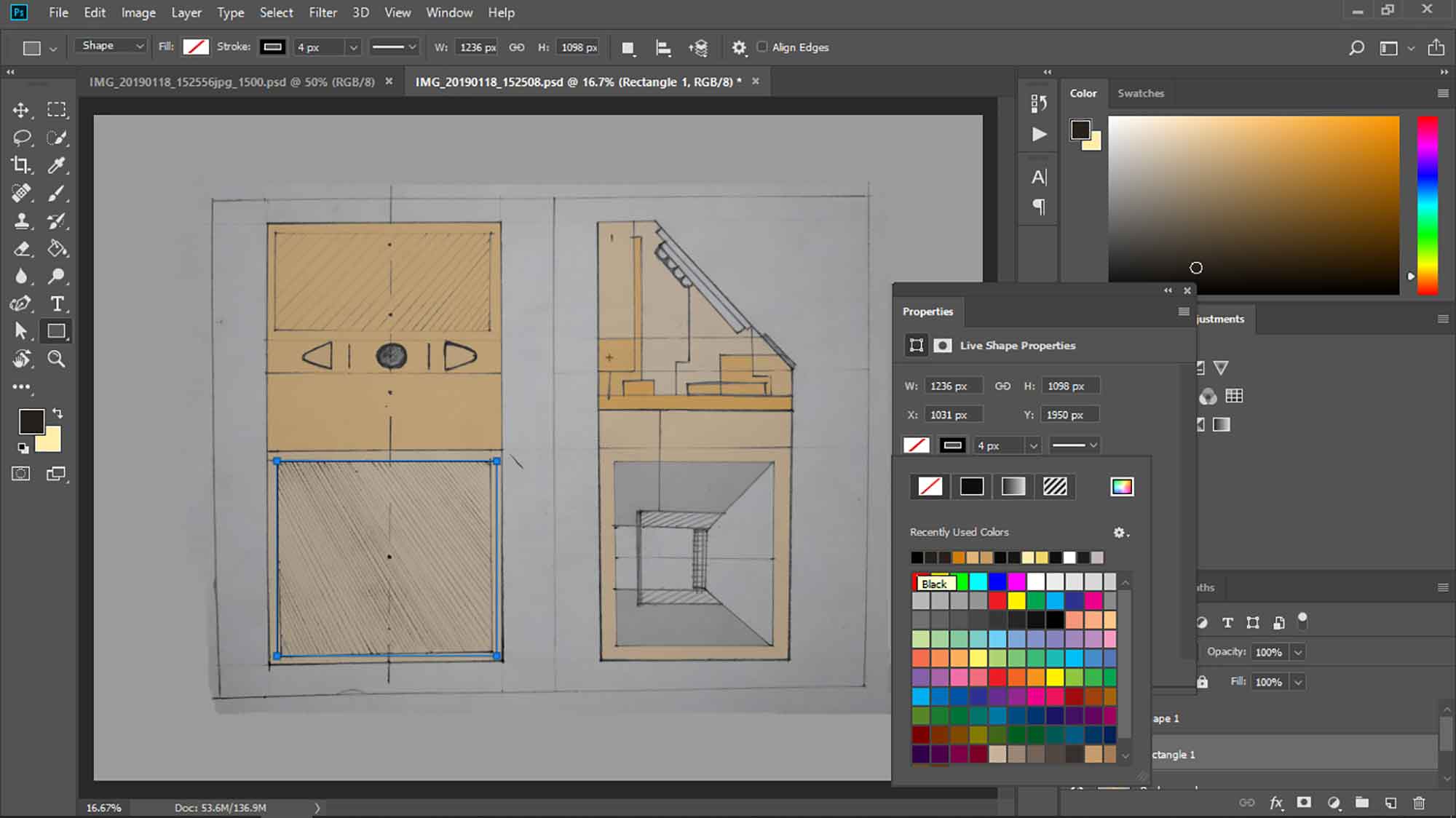
STEP 6 : Changing thickness
You can change thickness by small box there.
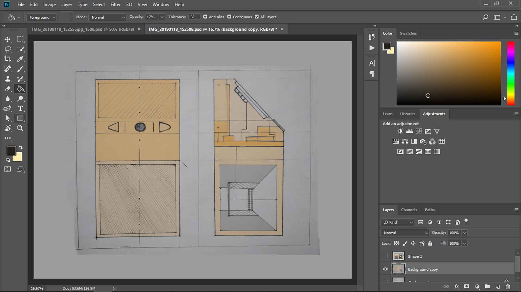
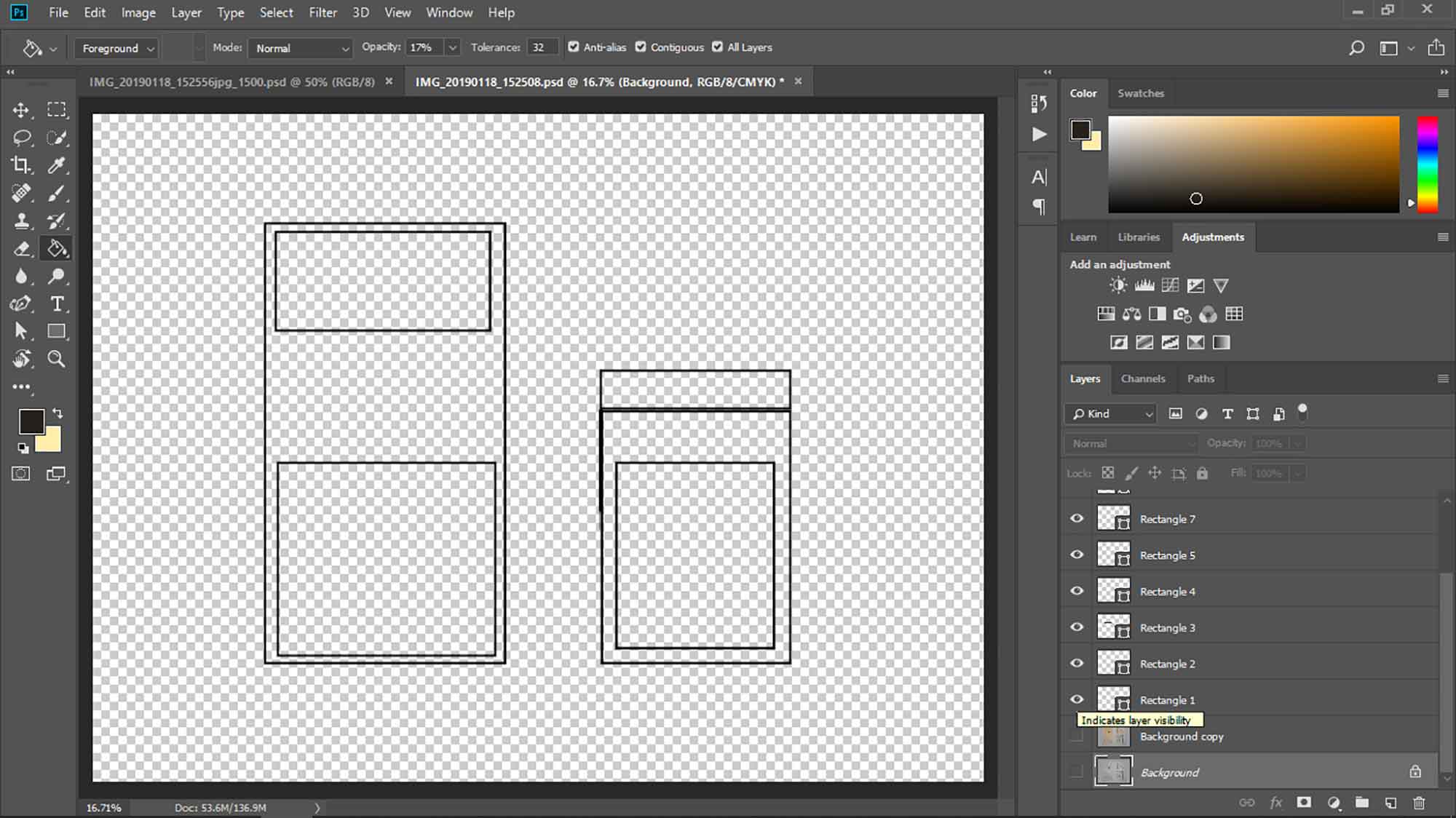
STEP 7 : individual operations in layer
By turning of the visibility of the background. you can see the individual rectangular here.
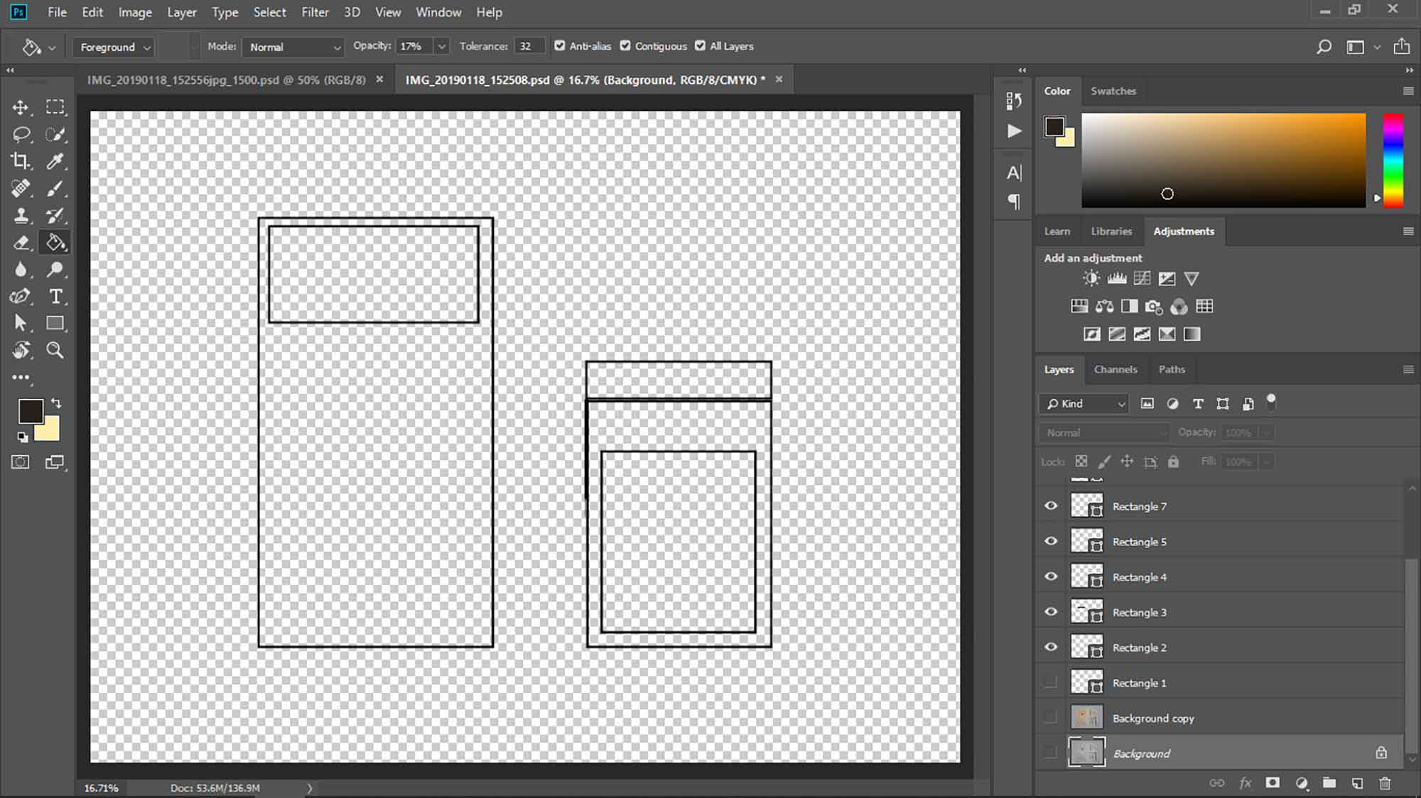
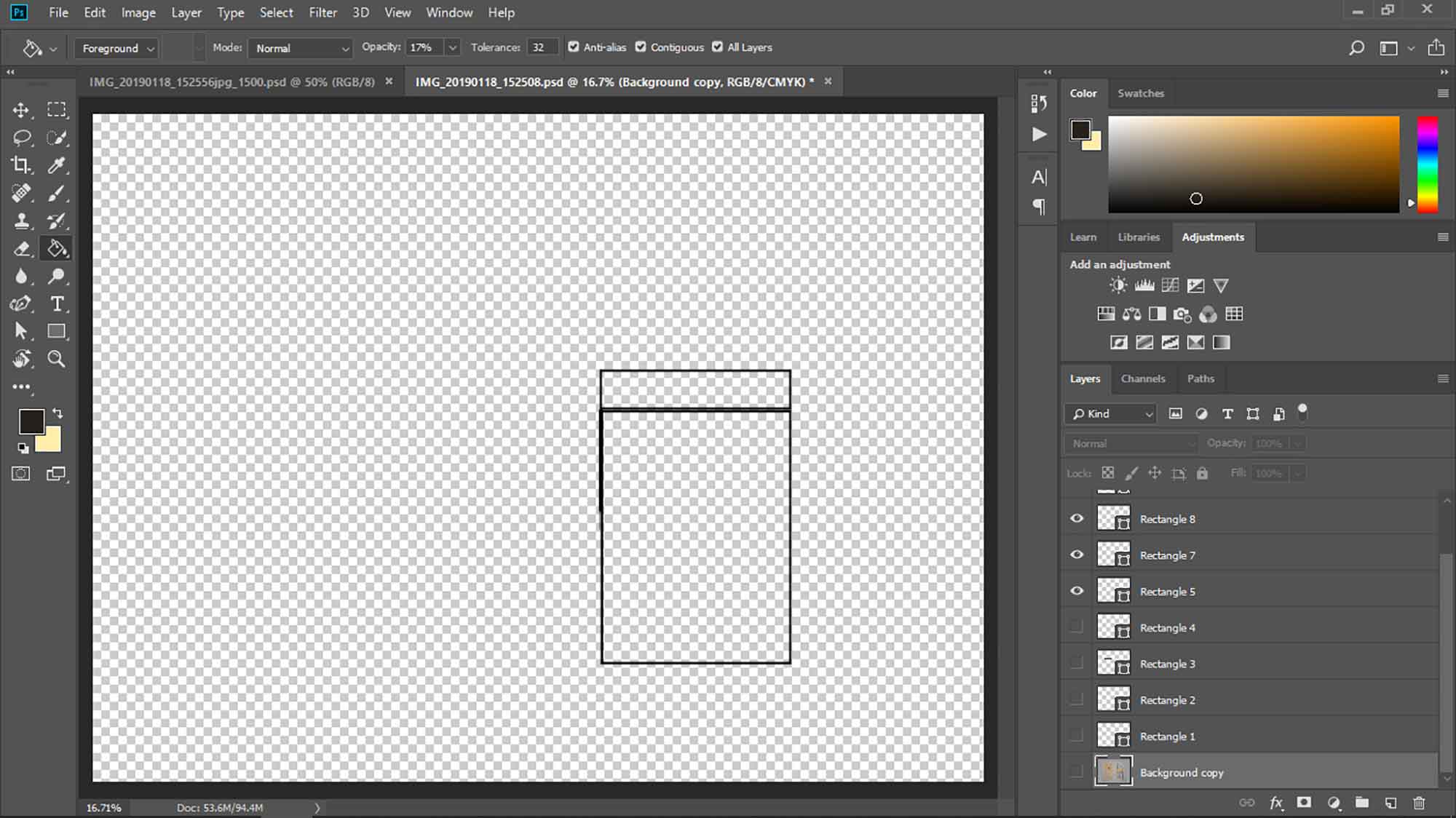
Turning off 4 rectangles
STEP 10 : Final image
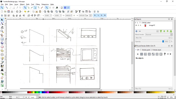
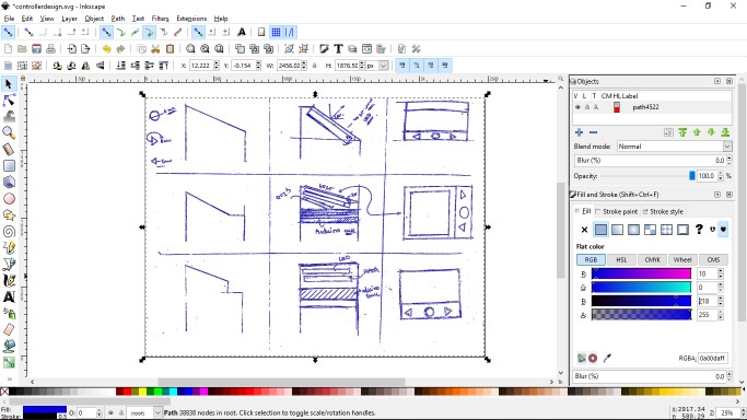
Converting images into vectors
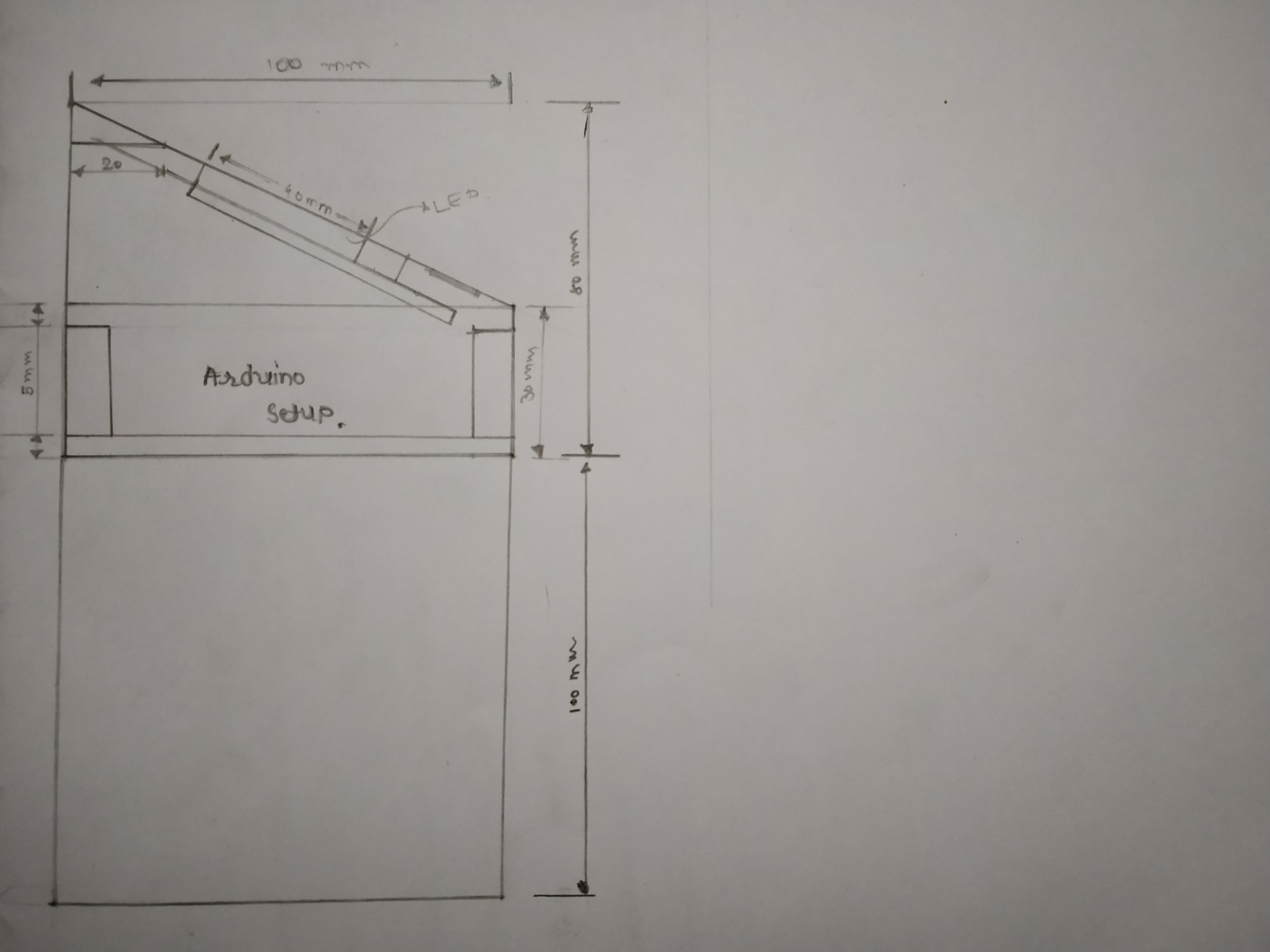
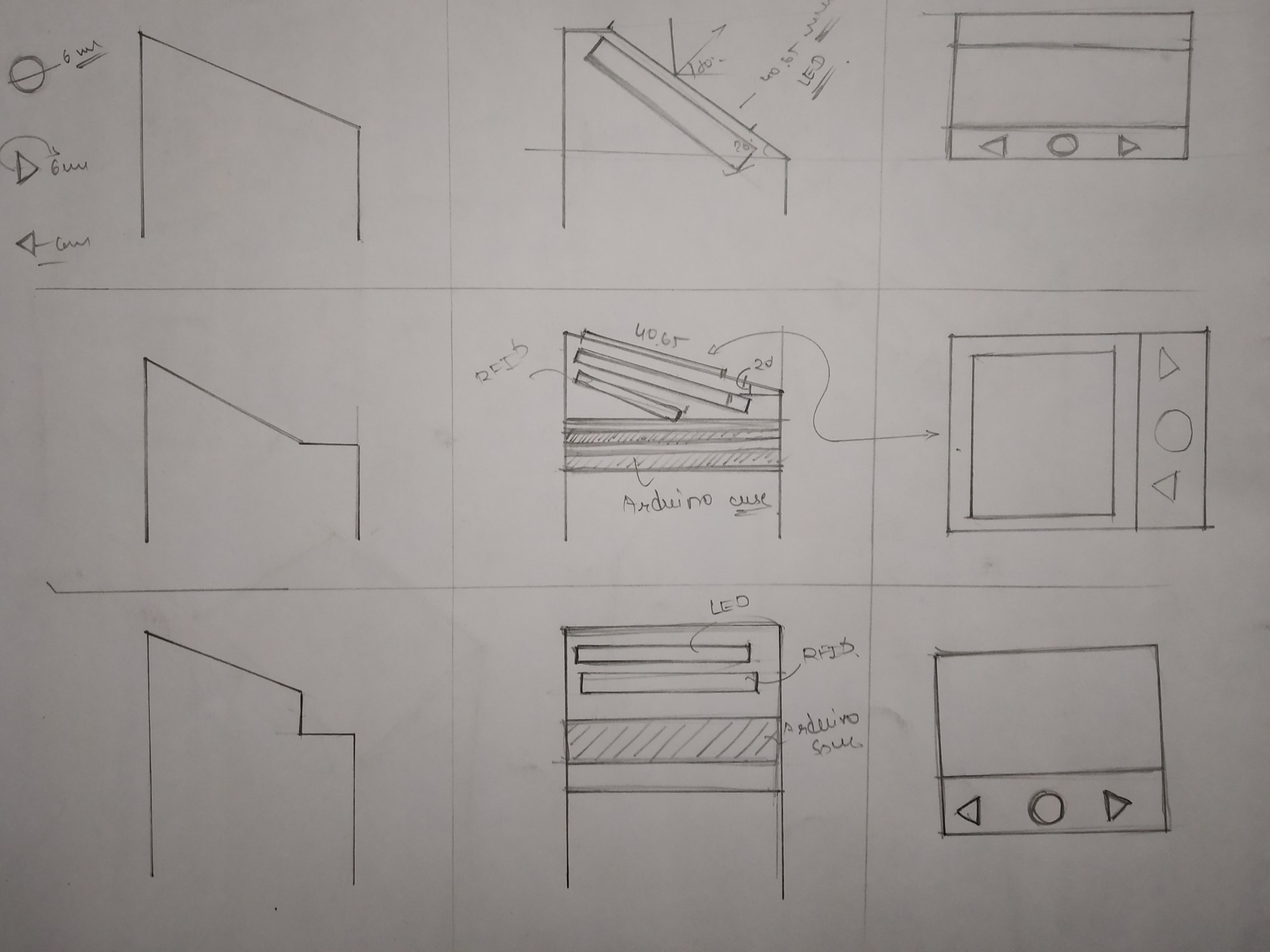
When you are working on projects, Starting with sketches of concepts gives it a good start. sketches are the simple and effective part of ideation. But sometimes we need to use those sketches in our computer work
like explaining clients your product concept, editing some part of your ideas. To do this we can convert these sketches into vector form.
some premium software like illustrator is giving excellent facilities in illustrations and stuff but I decided to go for photoshop and Inkscape. photoshop for clearing the brown-spots and Inkscape because I found
it great for previous Logo-design work and I want to know how effective it is for image scanning in being open-source. you will get to learn basics about photoshop too.
Sketches
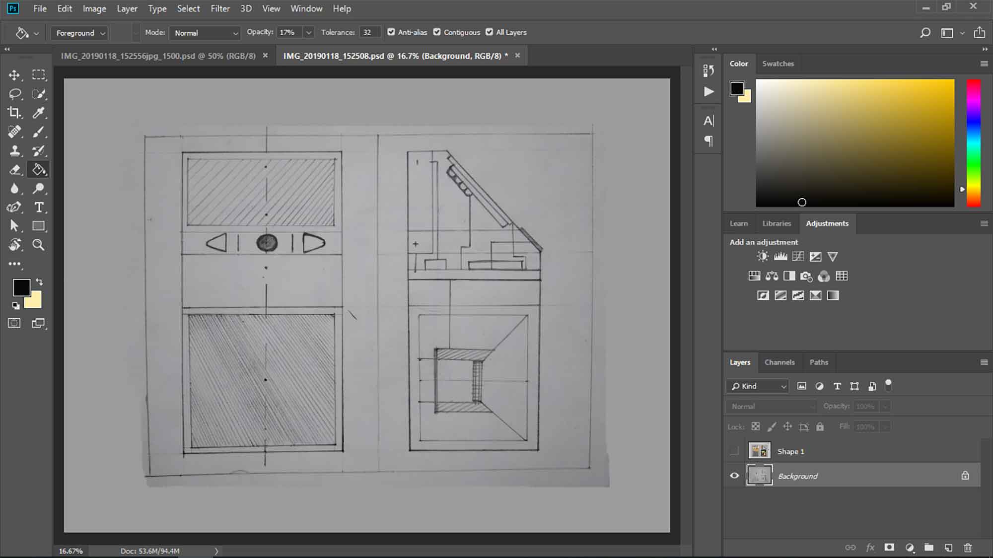
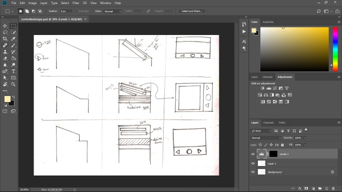
STEP 1 : Import sketches on photoshop
First import your sketches in photoshop. you will notice one layer panel (written background) on the left. It shows your edition layers. it is very helpful in doing a certain amount of tasks on pictures without affecting Some other work. you will learn more about layers, Click here.
STEP 2 : Use of layers
make new layer by pressing CTRL + J. by this your original picture will be safe for edit if some mistake occur. select that layer , now that layer is working layer ( Active layer).
STEP 3 : Select levels above
Follow these steps to open Color range. Color range will help you to find out brown-spots and you can minimize it. With an eye-dropper tool, you have to find one spot and with that, you can minimize every brown-spot every spot. For more about levels, Click here.
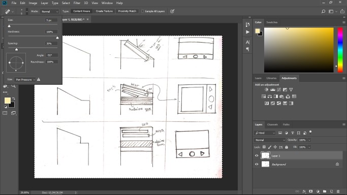
STEP 5 : use of spot healing tool
The new layer added to your layer panel if it is deleted only level effect will eliminate. Click spot healing brush showed in the second image. as the name tells it mixes up the image surface.
You can set values above for Tool.Now clean the spots! You can zoom in by ATL + scroll.
STEP 8:Exporting image for web
I've cleaned my images, After cleaning the images export for web. See the different types of export options.
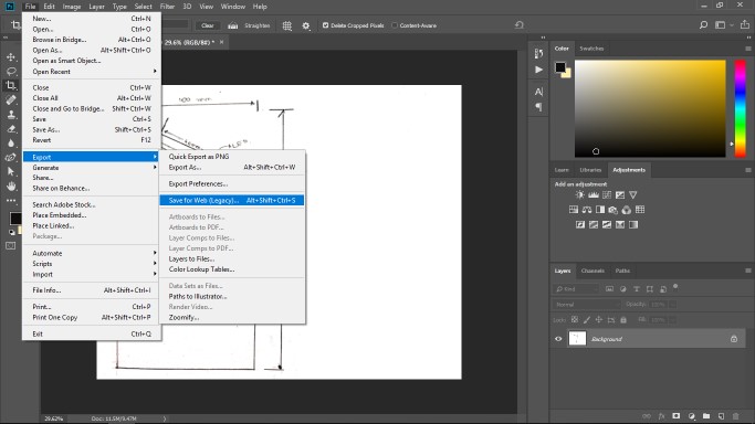
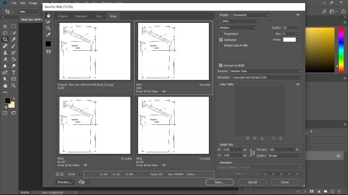
After selecting "Web option" select quality of image as your need and click save. Our photoshop work is finished norw open images in inkspace.
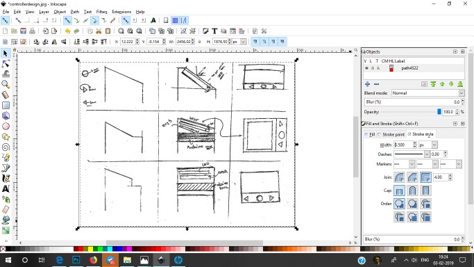
STEP 10: opening inscape for vectorizing image
give changes if you need , i have give basic idea of inkspace in above tutorial
STEP 11: steps to convert into vector
Follow this path to conver image in Vector form
keep this settings shown above, for your image different color values may needed
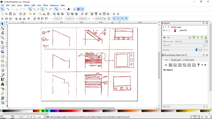
now image is converted into vector form, i can paint borders and do more stuff if i want to in vector image
final image:
yes! looks different. it can look more good if you use scanner or more if more finishing was done on sketches.
Autodesk for Drafting
For 3d modeling of my final modeling, I selected two software's : Autodesk And Fusion 360. I've good experience in cad with Fusion-360, Solidworks, and Rhino. I started with Autodesk. Below are some commands which are used commonly.
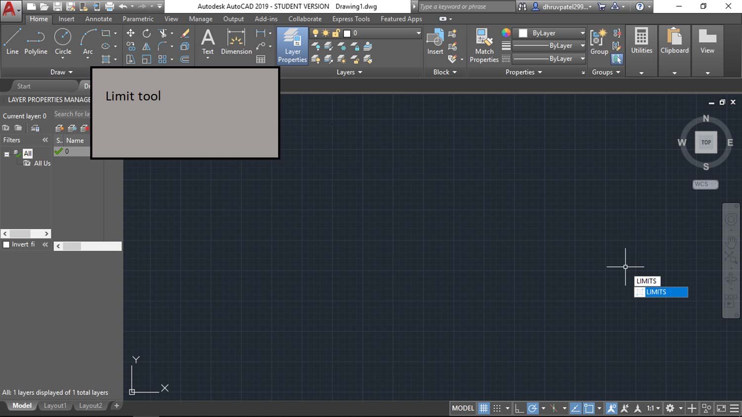
STEP 1 : Giving limits
First give limits in Autodesk for draw plain in specific region. Click here, Limit command.
STEP 2 : rectangle tool
Using rectangular tool for making front and top view of dustbin (only outer dimensions). Click here, Rectangle command.
STEP 3 : Layers in autodesk
You can also use layers in Autodesk for more complex drafts. Click here, Layer command.
Path : home > layers > layer properties.
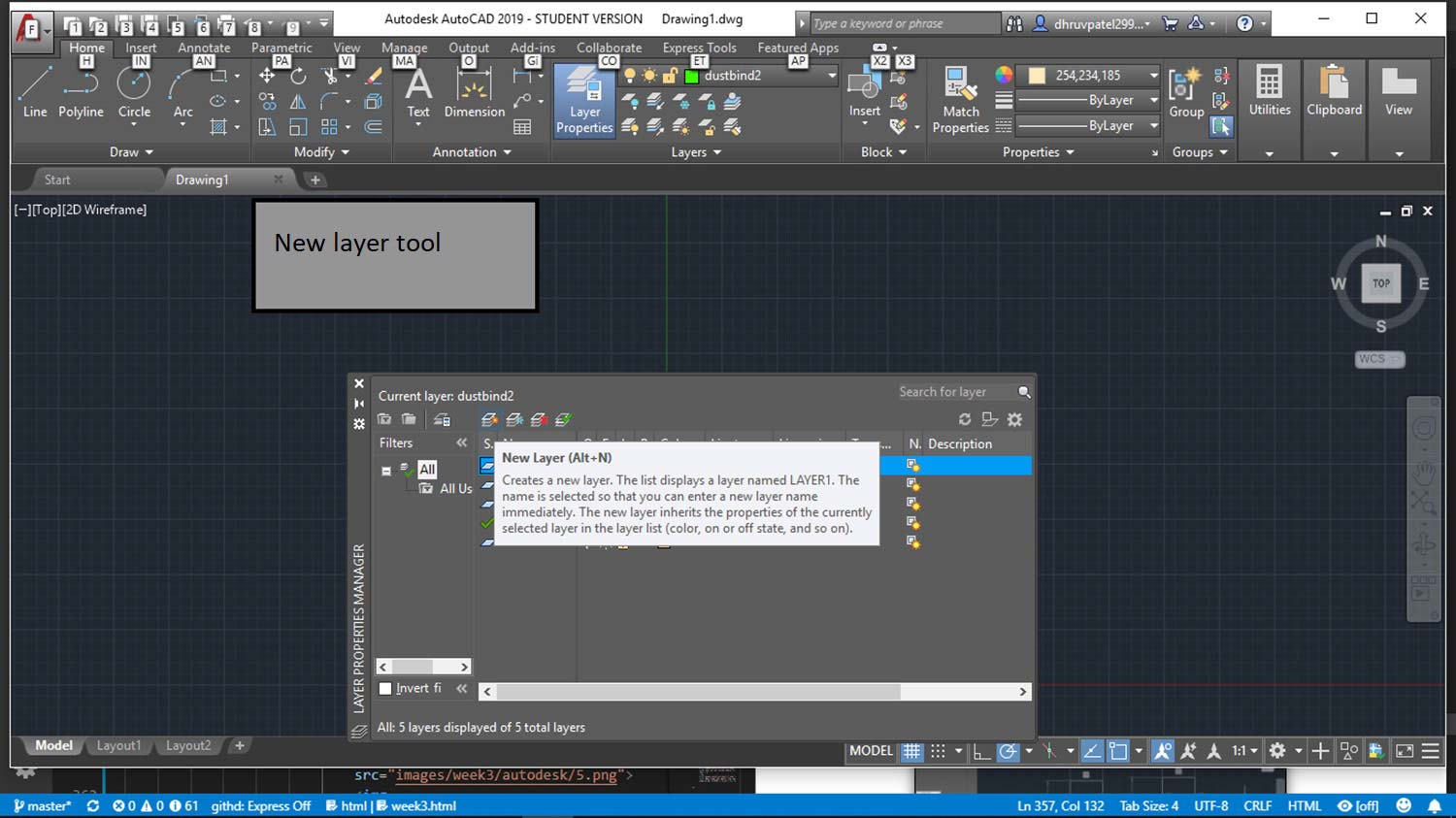
click to New Layer.
if there is a symbol of Snow make it symbol of Sun, it is sign of active layer.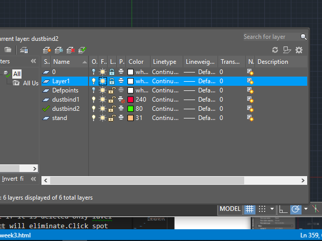
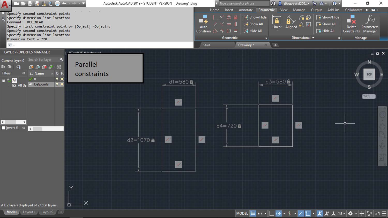
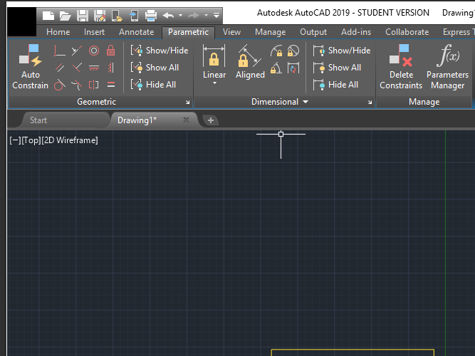
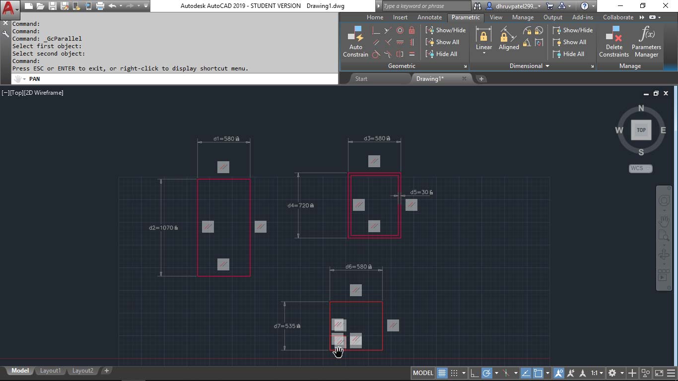
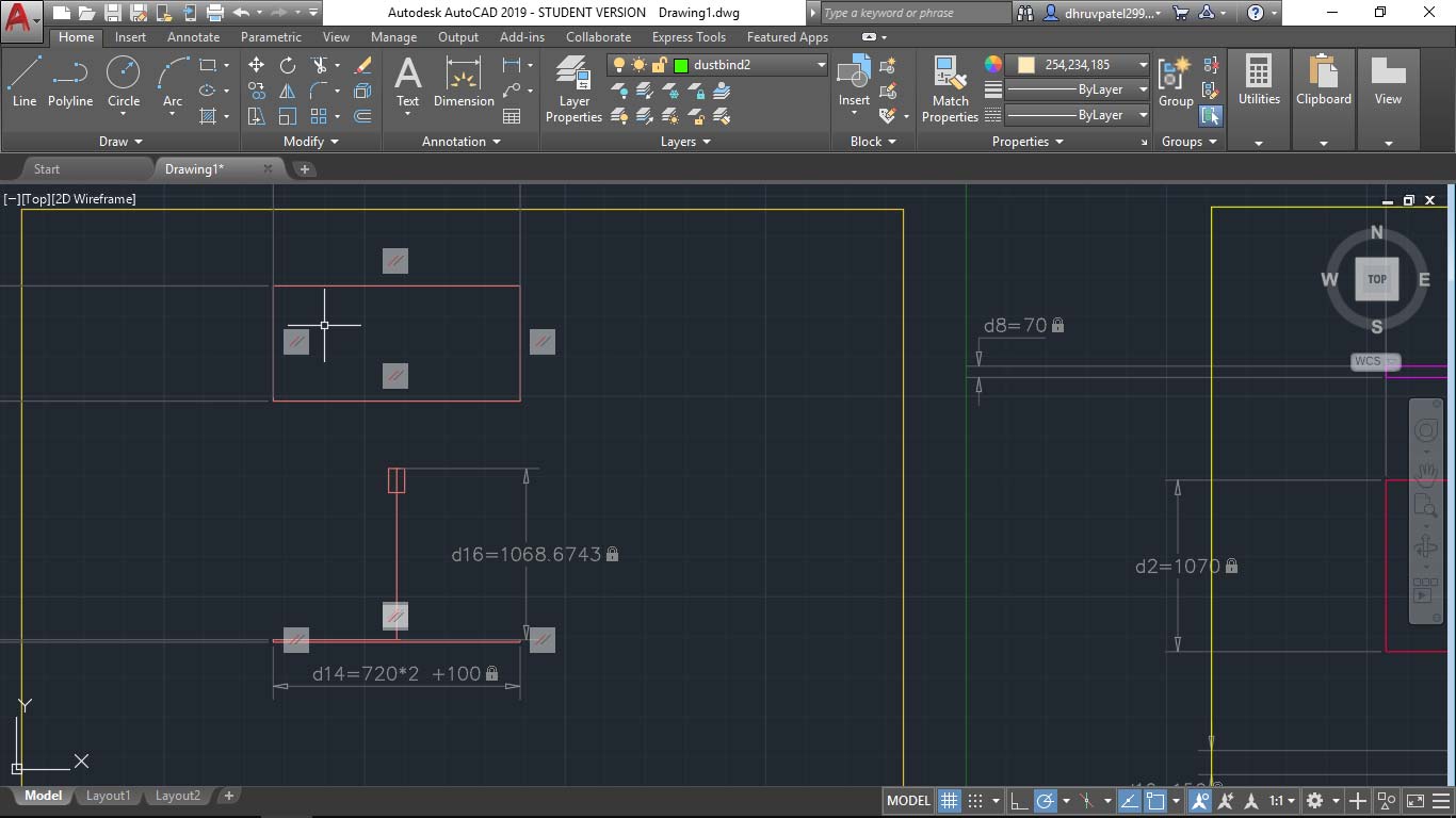
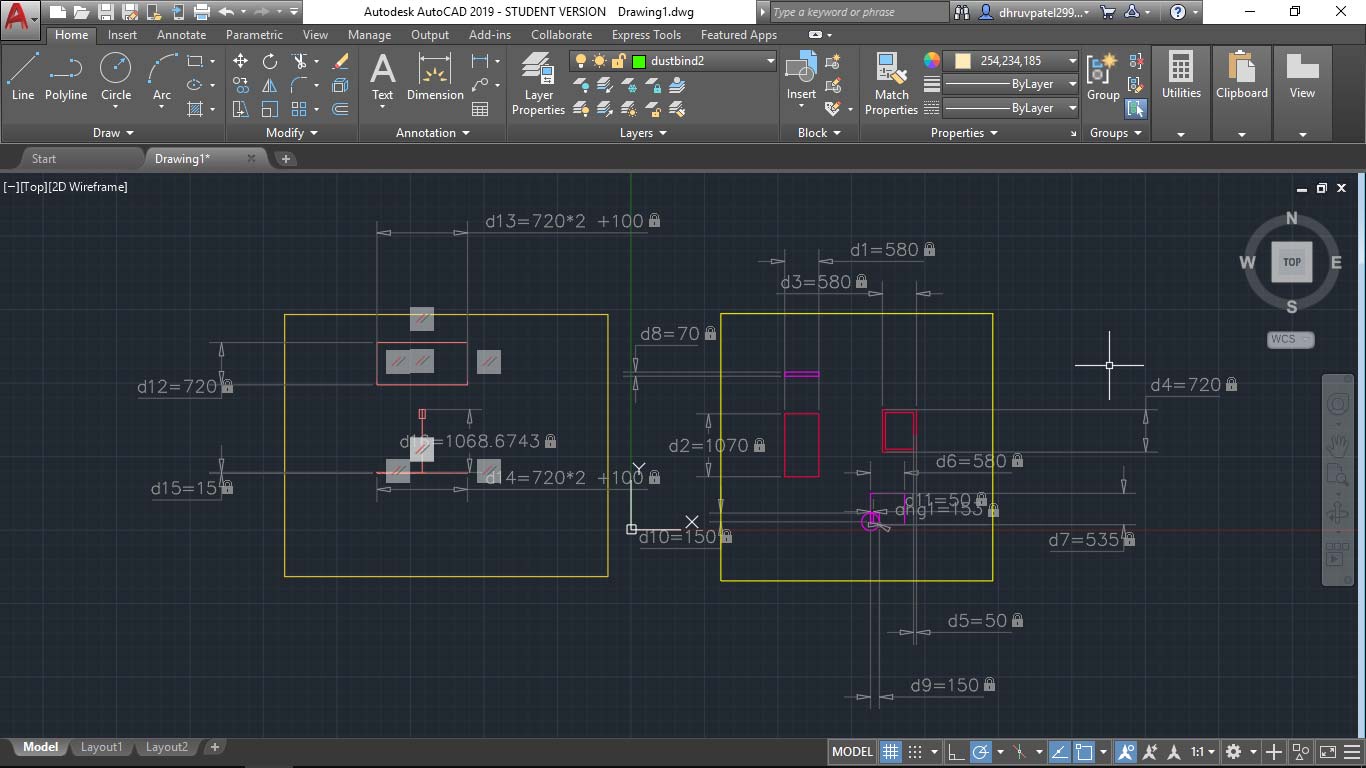
STEP 3d : Contrains and Dimensions
You can give constrains and change dimensions in parameters. Click here, Parametric Drawing and Constraints.
STEP 4 : colors to layers
You can also change color of layer.
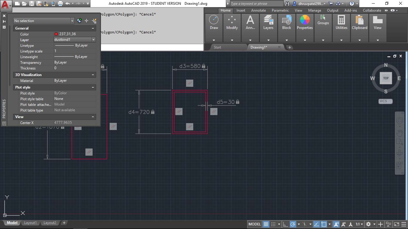
STEP 5 : property panel
On left, it is property panel you can open it by command line.
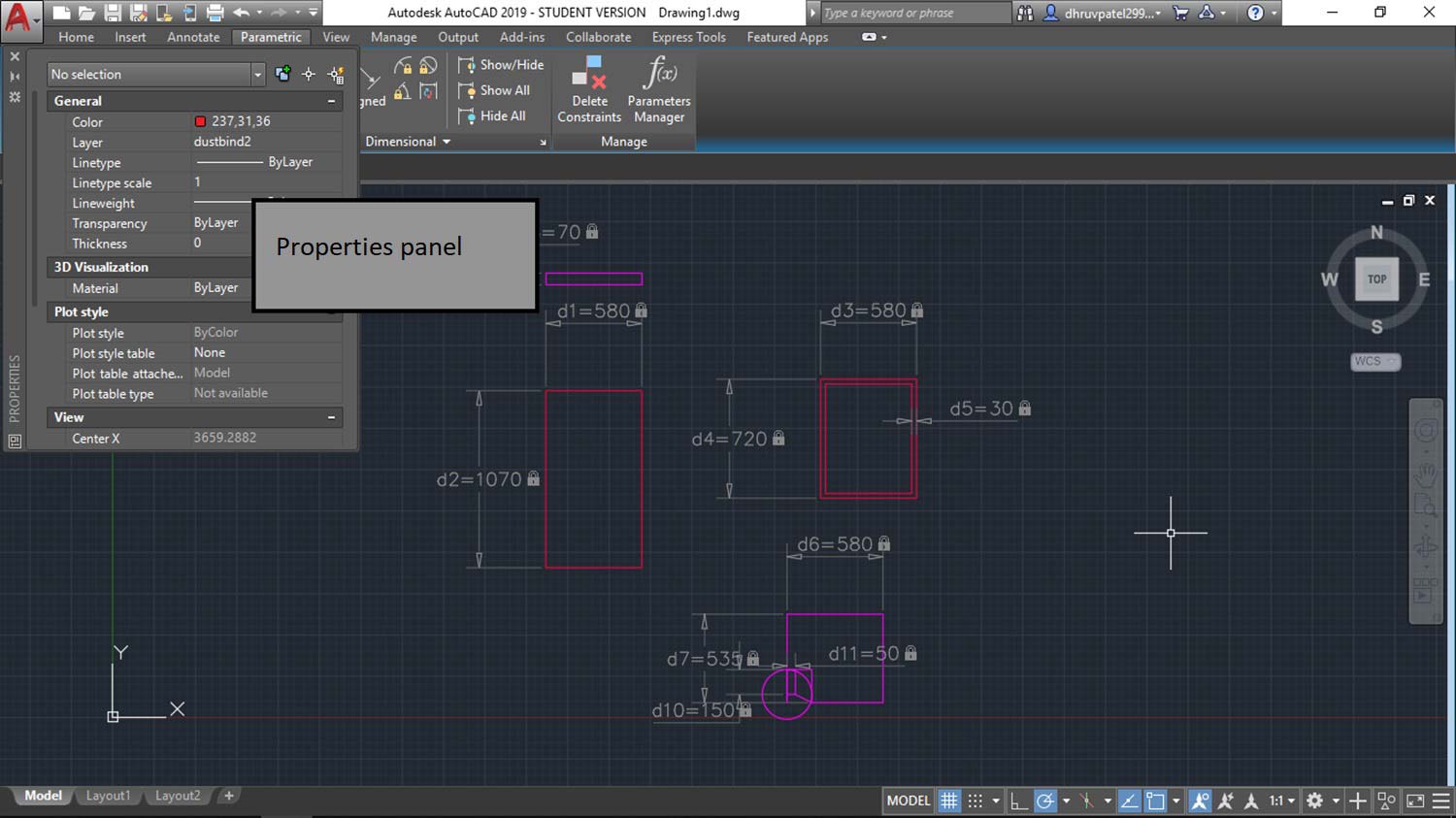
STEP 6 : Dimensions
Here's front view for my dustbin stand. only basic dimensions are given.
STEP 7 : Final image
Autodesk is great but it takes little time to learn. DWG file.
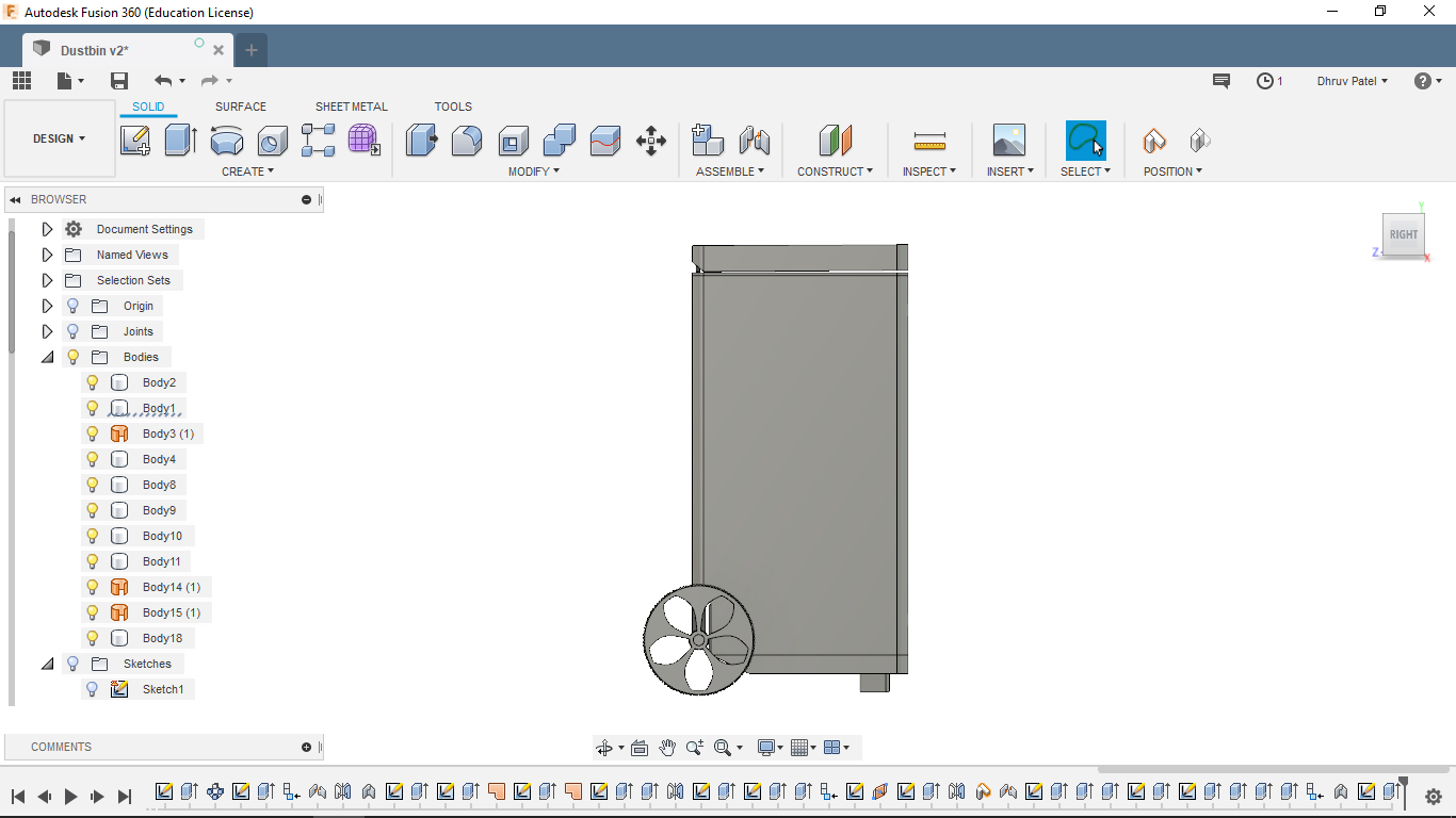
3D modeling in Fusion-360
I have good experience with fusion-360. It is well "FUSION" of Constructive solid modeling, Hard surface modeling, sheet-metal modeling, And simulation. yes, it includes everything and it is cloud-based software so takes minimum space.
I am going to show my step by step modeling process, and highlight important things.
STEP 1 : making dustbin body
In modeling one of the most common things is to create a sketch and extrude or giving it a third dimension. I created a profile sketch of my dustbin in the first one then in the second one I created the third dimension.
STEP 2: Using extrude cut
Just make a normal sketch on the plane of cut like shown in the figure.
STEp 3: making axle support for wheels
Repeating the same, sketch and extrude for making back support for wheels.
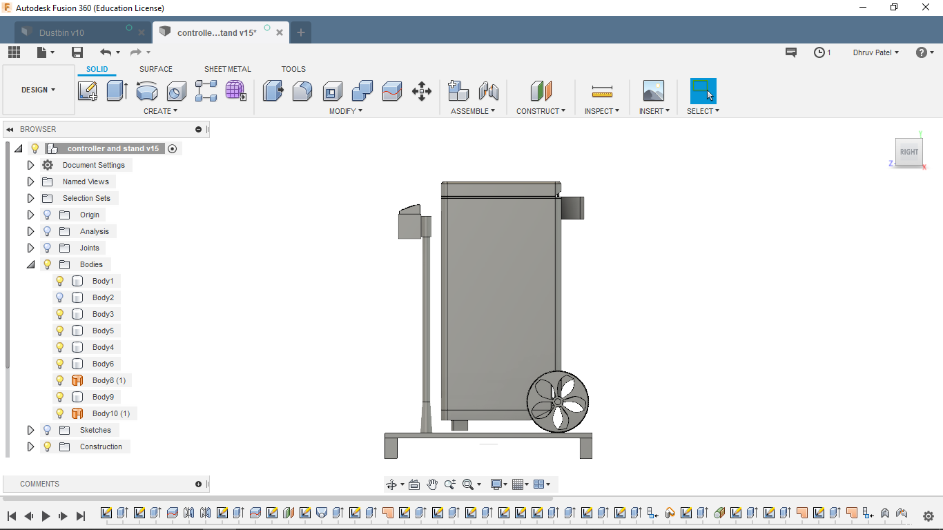
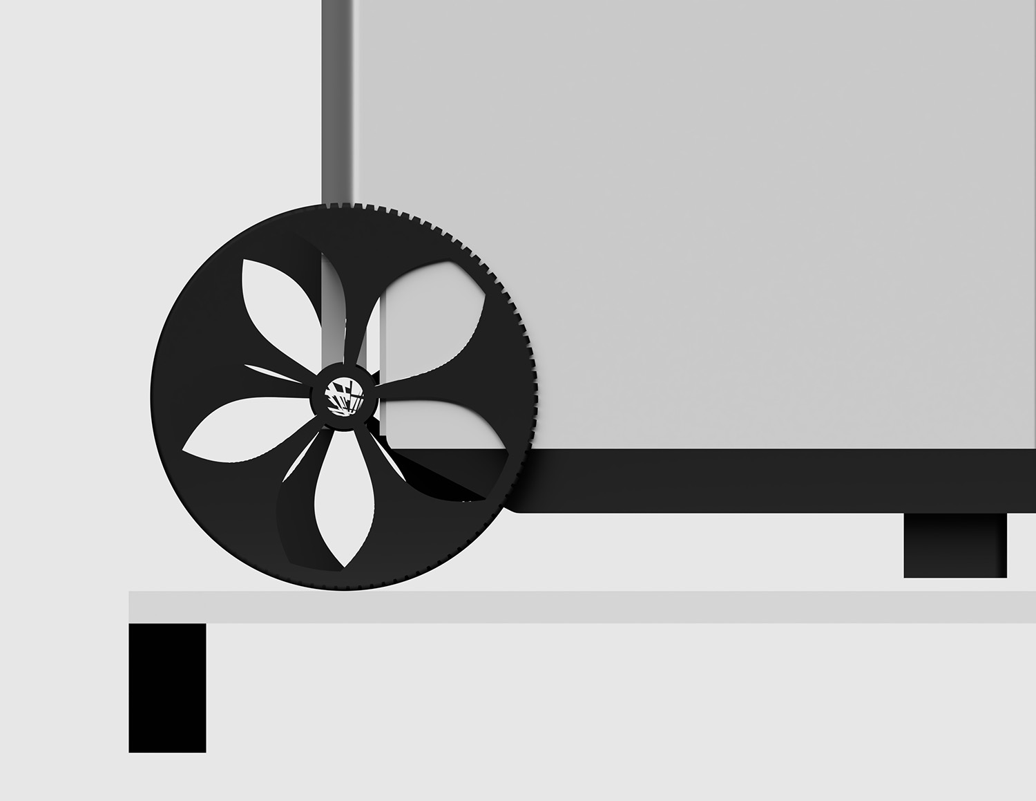
STEP 4: How to make wheels
First make a profile of wheel, by using revolve. Revolve is used make circular profile.
Path : create > patterns > circular pattern and click feature option, the select cut operation from timeline.
STEP 5: How to joint components
The wheels are ready! convert bodies in component by right-clicking on their name in Bodies and click create component. To joint the difference components use press J or SHIFT + j.
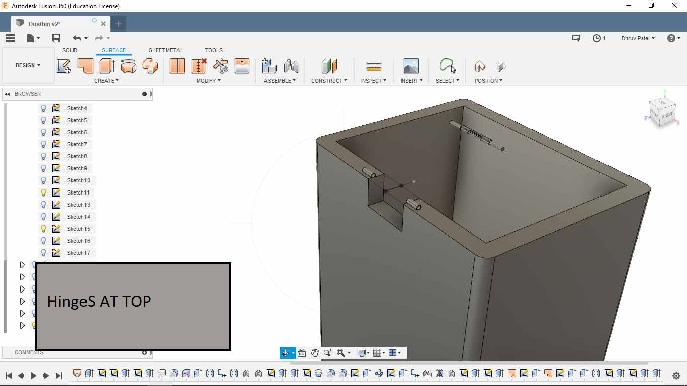
STEP 7:making hinges
Making hinges for opening.
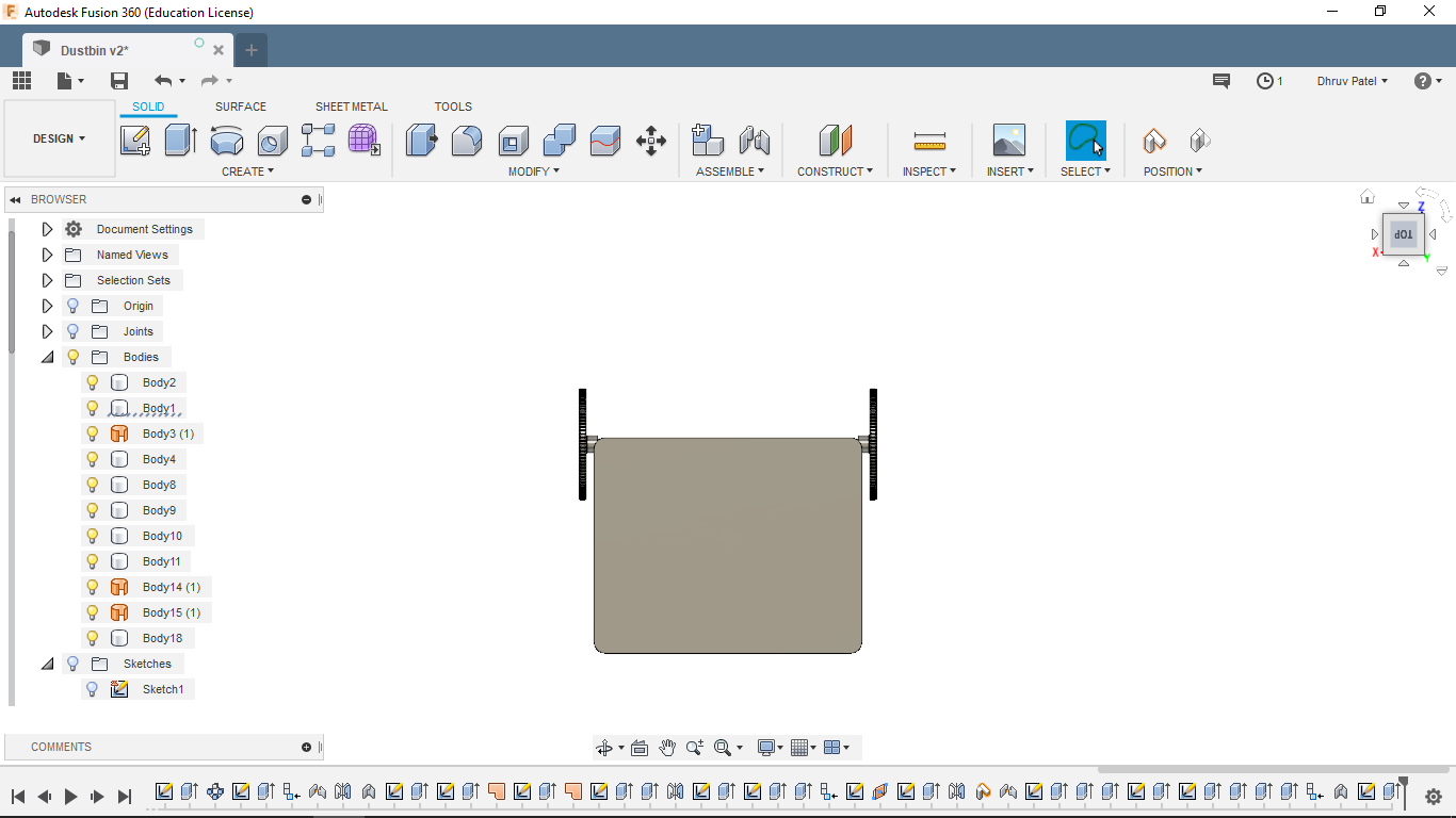
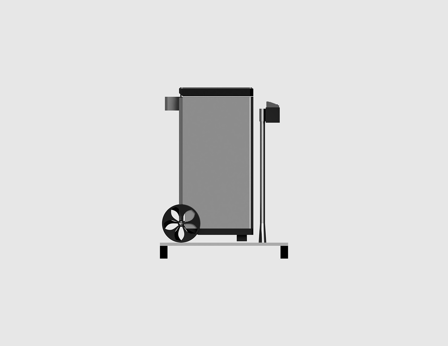
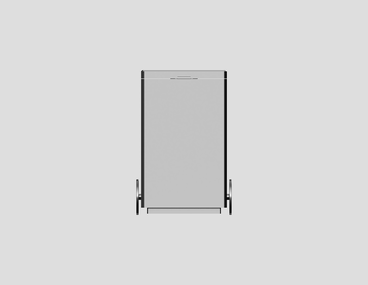
top-view of dustbin
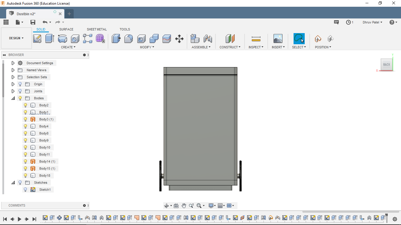
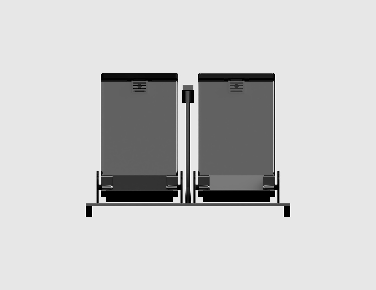
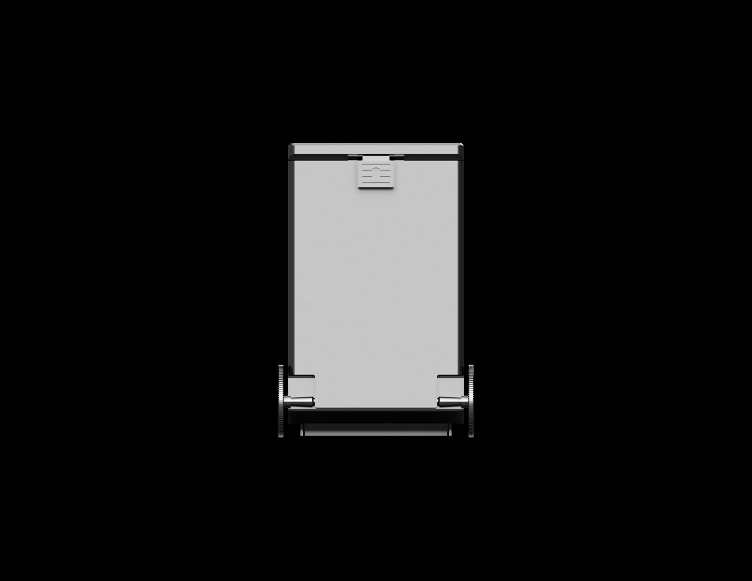
Back-view of dustbin
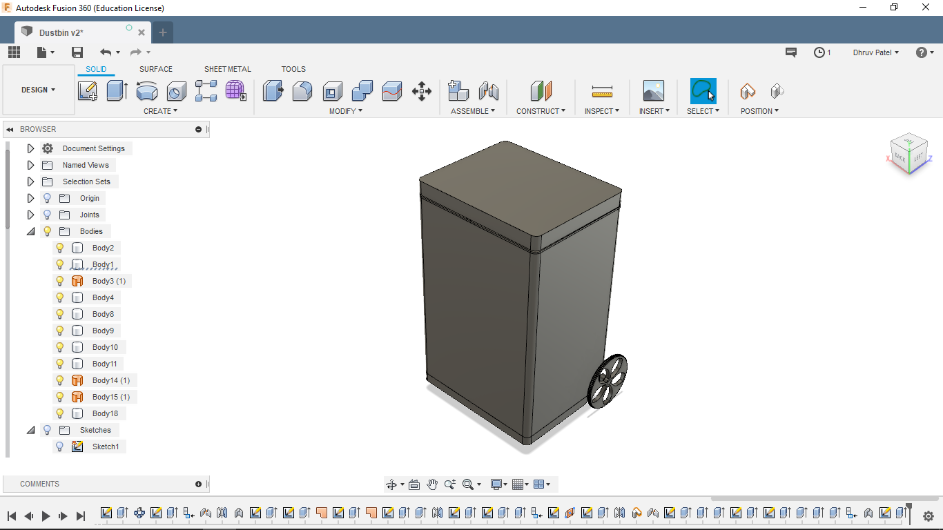
Isotropic view
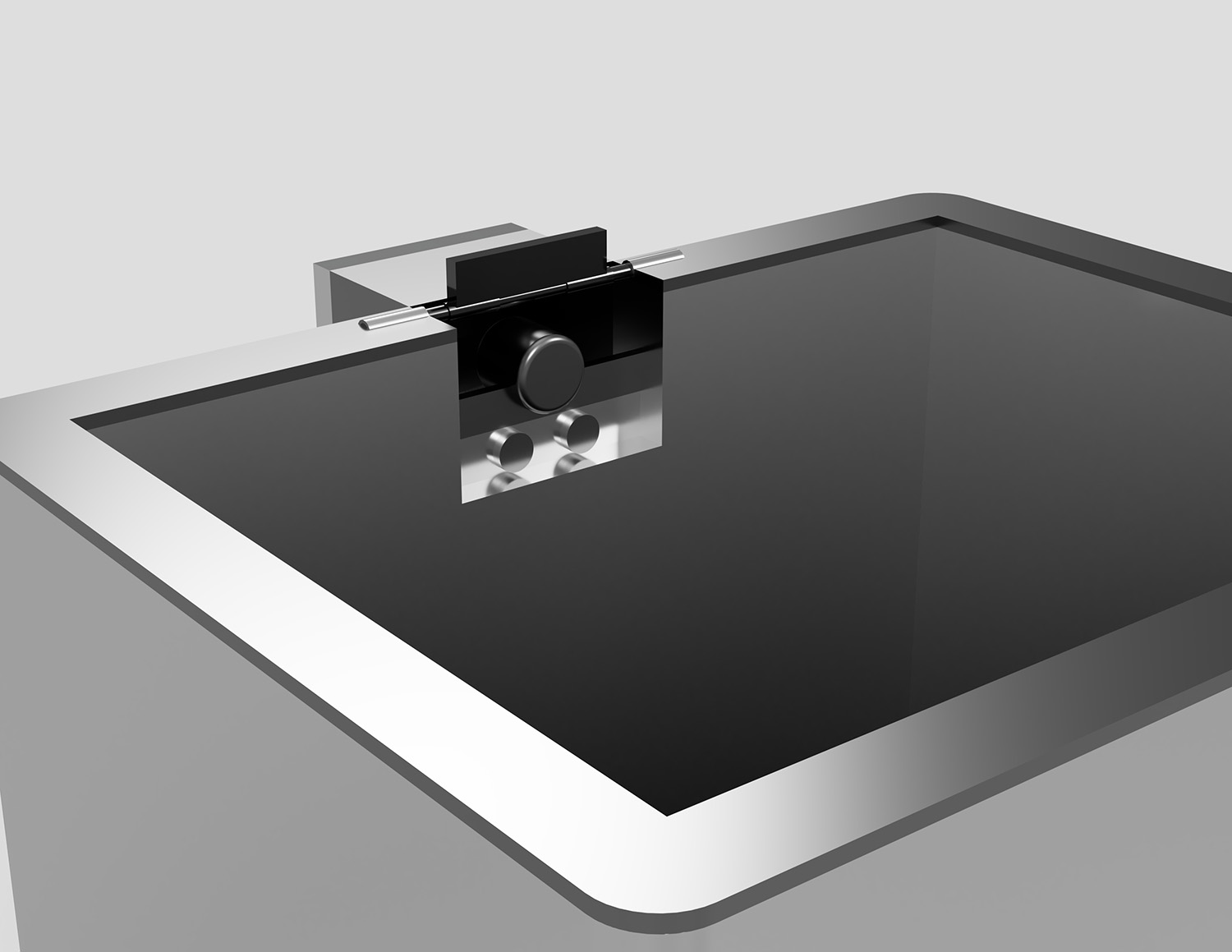
Back-controller of dustbin
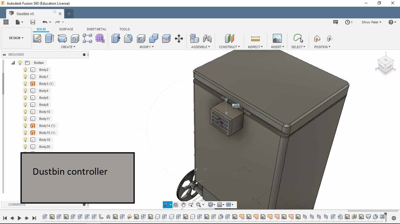
Section-view (inside of controller)
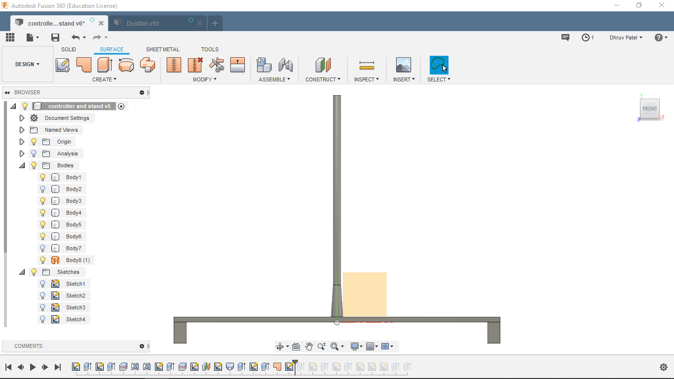
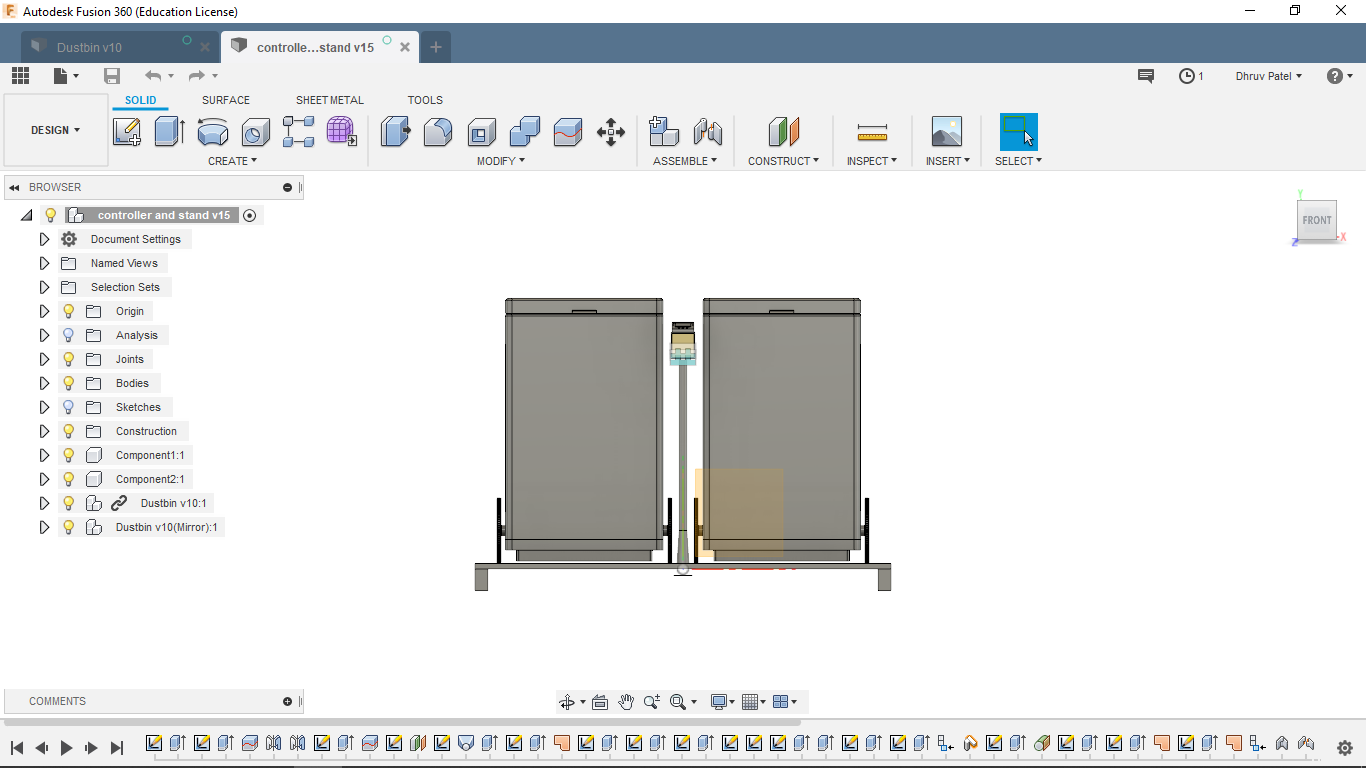
Dustbin stand
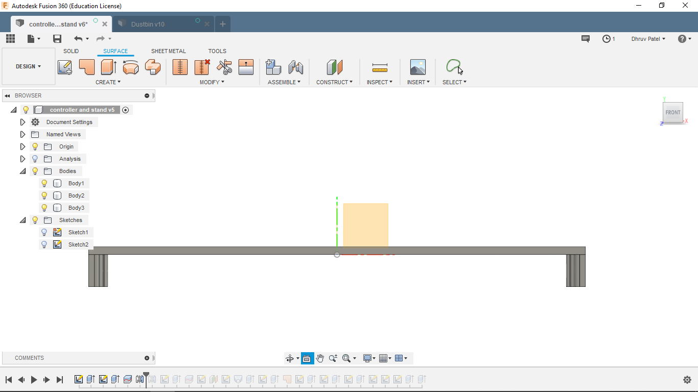
controller stand making process
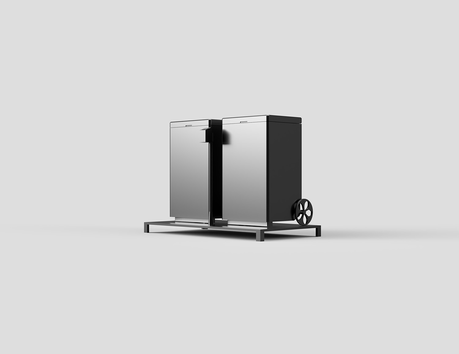
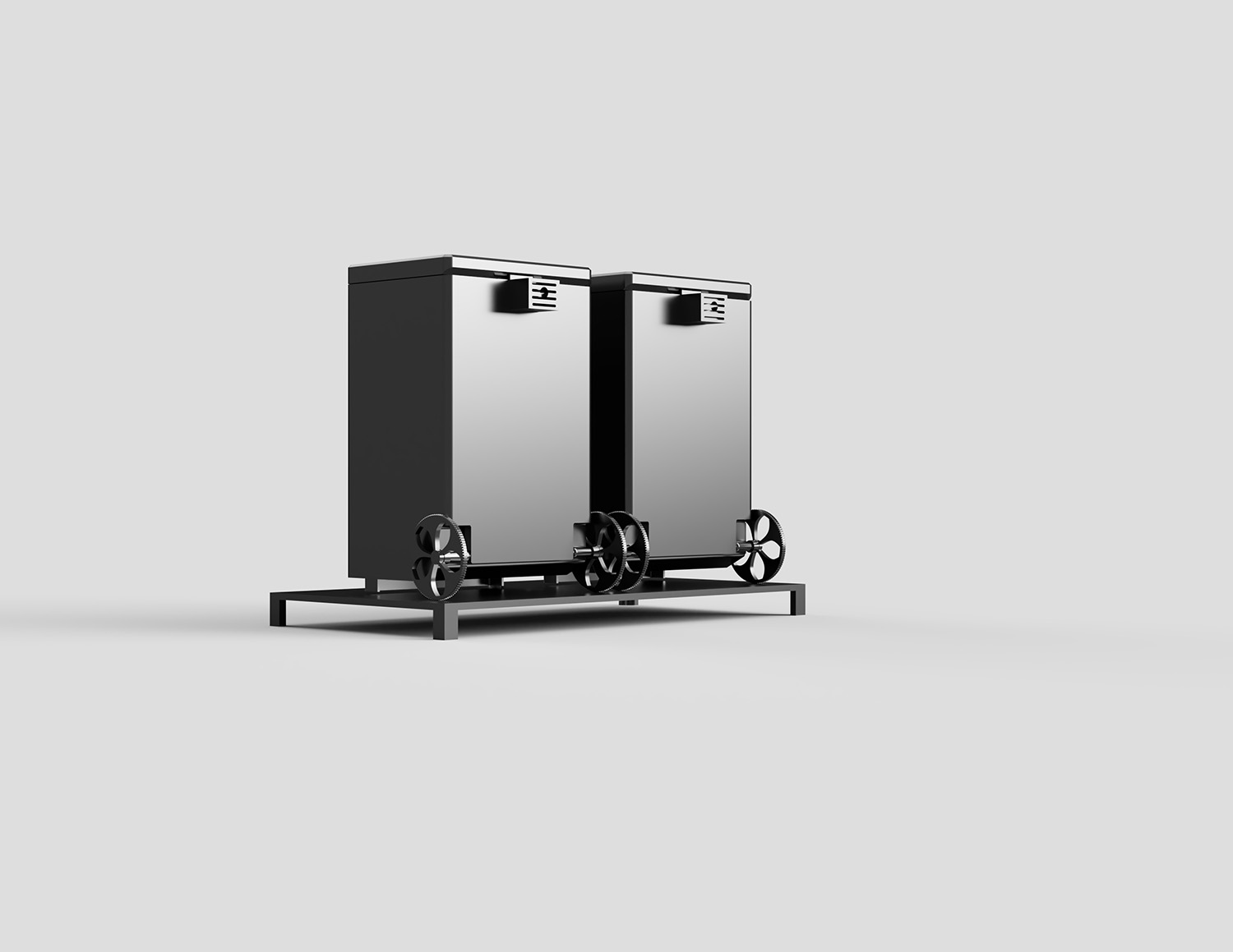
Full system
3D Model
The original CAD model can be downloaded Here. File for assembly .f3z file
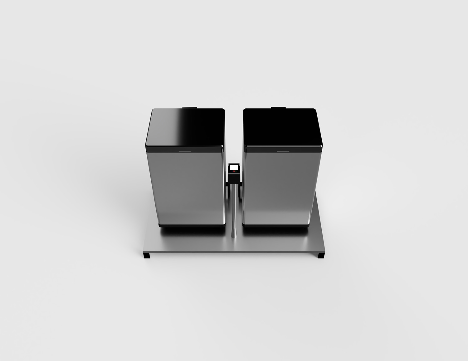
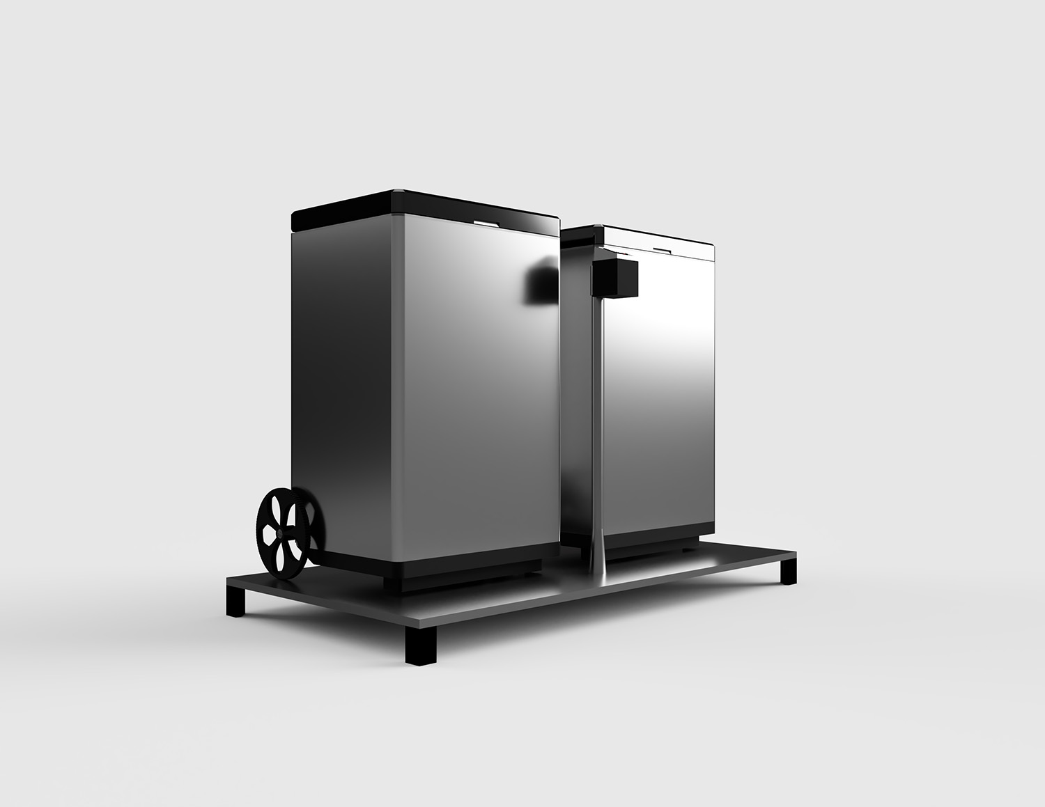
Renders of Smart-bin
Conclusion
This week I explored a lot, I am familiar with cad software so I got a chance to go deeper, I got time to Learn Photoshop and Inkscape. Also started exploring Autocad and fusion-360 more. in these software's, I love to work with Inkscape more. it is really good software, gives tools similar to premium software in the Free version.