Week 6 : Assignment
- design and 3D print an object (small, few cm3, limited by printer time) that could not be made subtractively
- 3D scan an object
In week 6 we are introduced to 3D Printing and Scanning. we get to know about the Addictive manufacturing process in which whole product or components are made by adding the material (by layer by layer or solidifying material).
Manufacturing process
Manufacturing processes are divided into three primary division's.- Addictive manufacturing
- Substractive manufacturing
- By forming the material
Additive Manufacturing (AM)
Additive Manufacturing (AM) is an appropriate name to describe the technologies that build 3D objects by adding layer-upon-layer of material, whether the material is plastic, metal, concrete, or one day…..human
tissue.
Additive Manufacturing application is limitless. Early use of AM in the form of Rapid Prototyping focused on preproduction visualization models. More recently, AM is being used to fabricate end-use products in aircraft, dental
restorations, medical implants,
automobiles, and even fashion products. Click here to know more !
Subtractive manufacturing
Subtractive manufacturing is CNC machining—a process that removes material from a larger piece of material through standard machining processes such as milling, turning/lathing or drilling until the prototype part is created. Click here to know more !
Metal forming
Forming, metal forming, is the metalworking process of fashioning metal parts and objects through mechanical deformation; the workpiece is reshaped without adding or removing material, and its mass remains unchanged. Forming operates on the materials science principle of plastic deformation, where the physical shape of a material is permanently deformed. Click here to know more !
3D printing
3D printing or additive manufacturing is a process of making three dimensional solid objects from CAD files (STL, obj).
3D printing is the opposite of subtractive manufacturing which is cutting out / hollowing out a piece of metal or plastic with for instance a milling machine. 3D printing enables you to produce complex (functional) shapes consuming less
material than traditional manufacturing methods.
3D printing is the opposite of subtractive manufacturing which is cutting out / hollowing out a piece of metal or plastic with for instance a milling machine.
3D printing enables you to produce complex (functional) shapes using less material than traditional manufacturing methods.
Click Here! for more information.
Types of 3d printers
1) Stereolithography (SLA)
SLA is a fast prototyping process. Those who use this technology are serious about accuracy and precision. Machines that use this technology produce unique models, patterns, prototypes, and various production parts.
They do this by converting
liquid photopolymers (a special type of plastic) into solid 3D objects, one layer at a time. The plastic is first heated to turn it into a semi-liquid form, and then it hardens
on contact. The printer constructs each of these layers using an ultraviolet laser, directed by X and Y scanning mirrors. Just before each print cycle, a recoater blade moves across the surface to ensure each thin layer of
resin spreads
evenly across the object. The print cycle continues in this way, building 3D objects from the bottom up.
2) Digital Light Processing (DLP)
DLP is the oldest of the 3D printing technologies, created by a man called Larry Hornbeck back in 1987.
It’s similar to SLA, given
that it also works with
photopolymers. The liquid plastic resin used by the printer goes into a translucent resin container. There is, however, one major difference between the two, which is the source of light. While SLA uses ultraviolet
light, DLP uses a more
traditional light source, usually arc lamps. This process results in pretty impressive printing speeds. When there’s plenty of light, the resin is quick to harden (we’re talking seconds). Compared to SLA 3D printing, DLP
achieves quicker
print times for most parts.
3) Fused Deposition Modeling (FDM)
FDM is a 3D printing process developed by Scott Crump and then implemented by Stratasys Ltd, in the 1980s.
It uses production-grade thermal plastic materials to print its 3D objects. It’s popular for producing functional prototypes, concept
models, and manufacturing aids. It’s a technology that can create accurate details and boasts an exceptional strength to weight ratio.
Before the FDM printing process begins, the user has to slice the 3D CAD data (the 3D model) into multiple layers using special software. The sliced CAD data goes to the printer which then builds the object layer at a time on the build
platform. It does this simply by heating and then extruding the thermoplastic filament through the nozzle and onto the base. The printer can also extrude various support materials as well as the thermoplastic.
4) Selective Laser Sintering (SLS)
It’s a 3D printing technique that uses high power CO2 lasers to fuse particles. The laser sinters powdered metal materials (though it can utilize other materials too, like white nylon powder, ceramics, and even glass). Here’s how it works:
The build platform, or bed, lowers incrementally with each successive laser scan. It’s a process that repeats one layer at a time until it reaches the object’s height. There is un-sintered support from other powders during the build process
that surrounds and protects the model. This means the 3D objects don’t need other support structures during the build. Someone will remove the un-sintered powders manually after printing. SLS produces durable, high precision parts, and it
can use a wide range of materials.
5) Selective Laser Melting (SLM)
SLM made its debut appearance back in 1995.
It was part of a German research project at the Fraunhofer Institute ILT, located in the country’s most western city of Aachen. Like SLA (see above), SLM also uses a high-powered laser beam to form 3D parts. During the
printing process, the laser beam melts and fuses various metallic powders.
6) Electron Beam Melting (EBM)
A Swedish company called Arcam AB founded EBM® in 1997.
This is a 3D printing technology similar to SLM (see above), in that it uses a powder bed fusion technique. The difference between the two is the power source. The SLM approach above
uses a high-powered laser in a chamber of noble, or inert gas. EBM, on the other hand, uses a powerful electron beam in a vacuum.
7) Laminated Object Manufacturing (LOM)
LOM is a rapid prototyping system that works by fusing or laminating layers of plastic or paper using both heat and pressure. A computer-controlled blade or laser cuts the object to the desired shape. Once each printed layer is complete, the platform moves down by about 1/16th of an inch, ready for the next layer.
Voronoi pattern
For 3d Printing, I need to have some 3d model which is difficult to build by the subtractive manufacturing process in other words it can't be made by just removing the material.
I choose Rhino(version 6) with Grasshopper. I found this software very helpful to generate creative shapes.
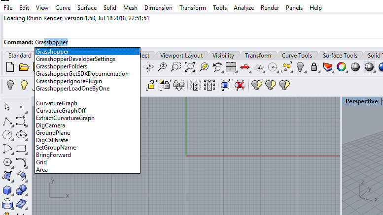
Open Grasshopper in rhino
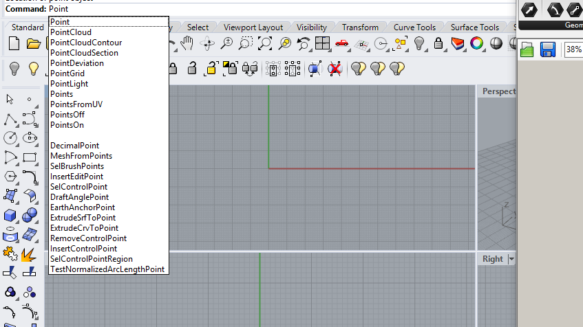
Active Point tool
you can active commands by writing the command name on the command line.
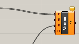
Active voronoi comand in Grasshopper
Double click and type Voronoi. Voronoi is a command which will help us to generate different patterns on the surface.
It works on beautiful mathematical concept in which set of local points have their effective area. this areas are represents points minimum distance compare to other points. Click
here to know more.
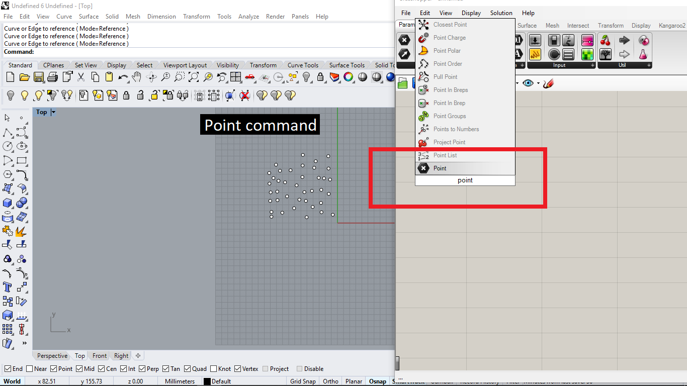
Open point mod
Right click on point mode
Select multiple point option
Select points which are generated on rhino
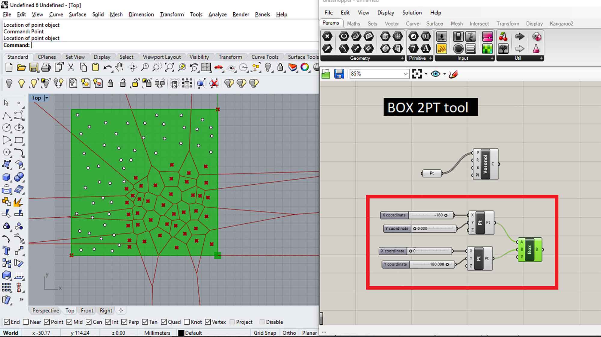
Add Box 2pt tool
By adding the BOX 2Pt tool you can insert point(nonphysical point - you cant select it with the mouse). it will help to give boundaries to the Voronoi pattern.
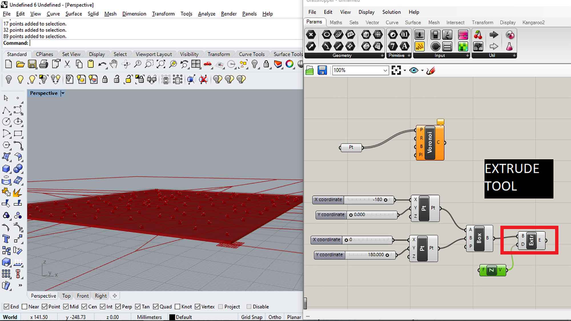
Extrude the Box
extrude the box by extruding command in grasshopper.
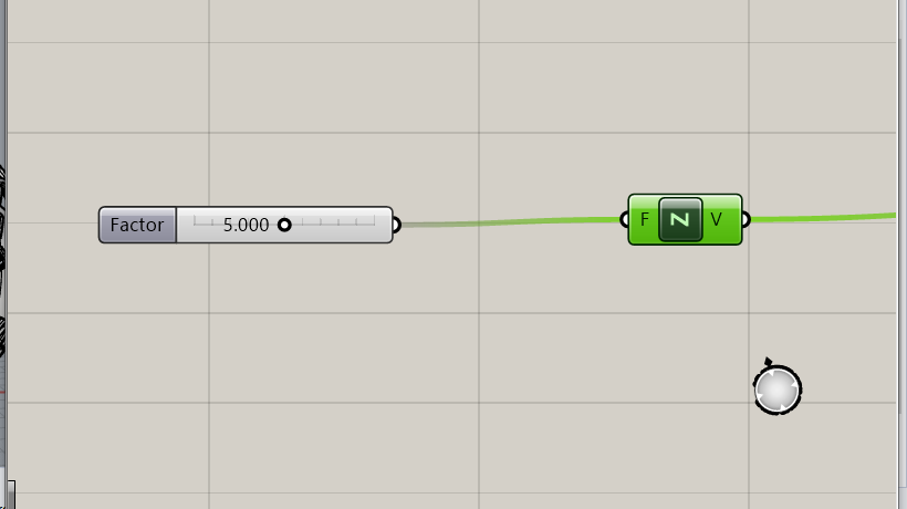
Add Unit z mod and connect it with the Direction point of extruding.
You have to add a number slider to Unit Z.
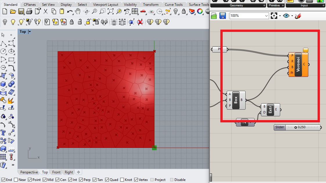
Define boundary of Voronoi pattern
Connect box output with the boundary junction of Voronoi mod. you can see the voronoi diagram has one boundary now.
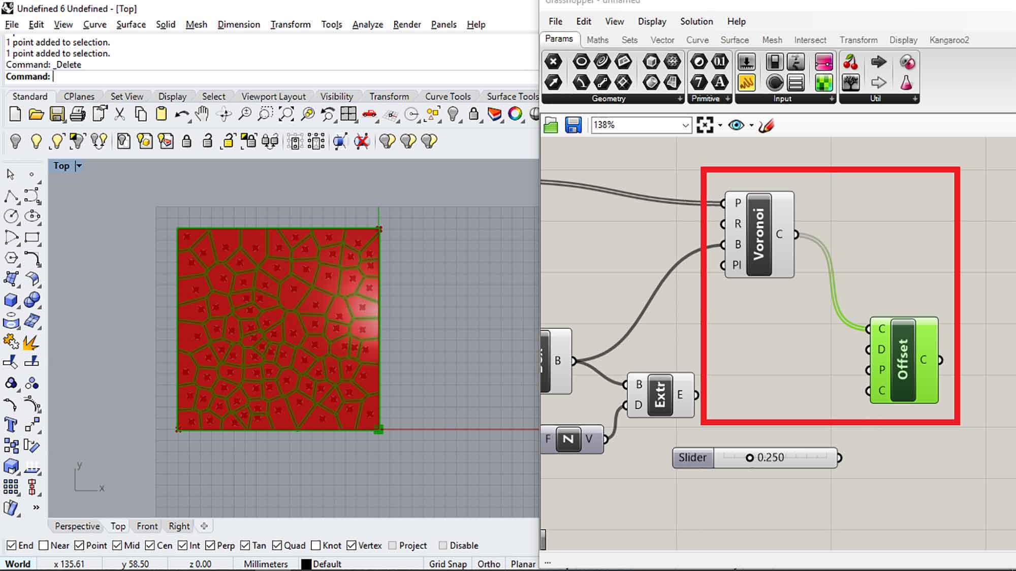
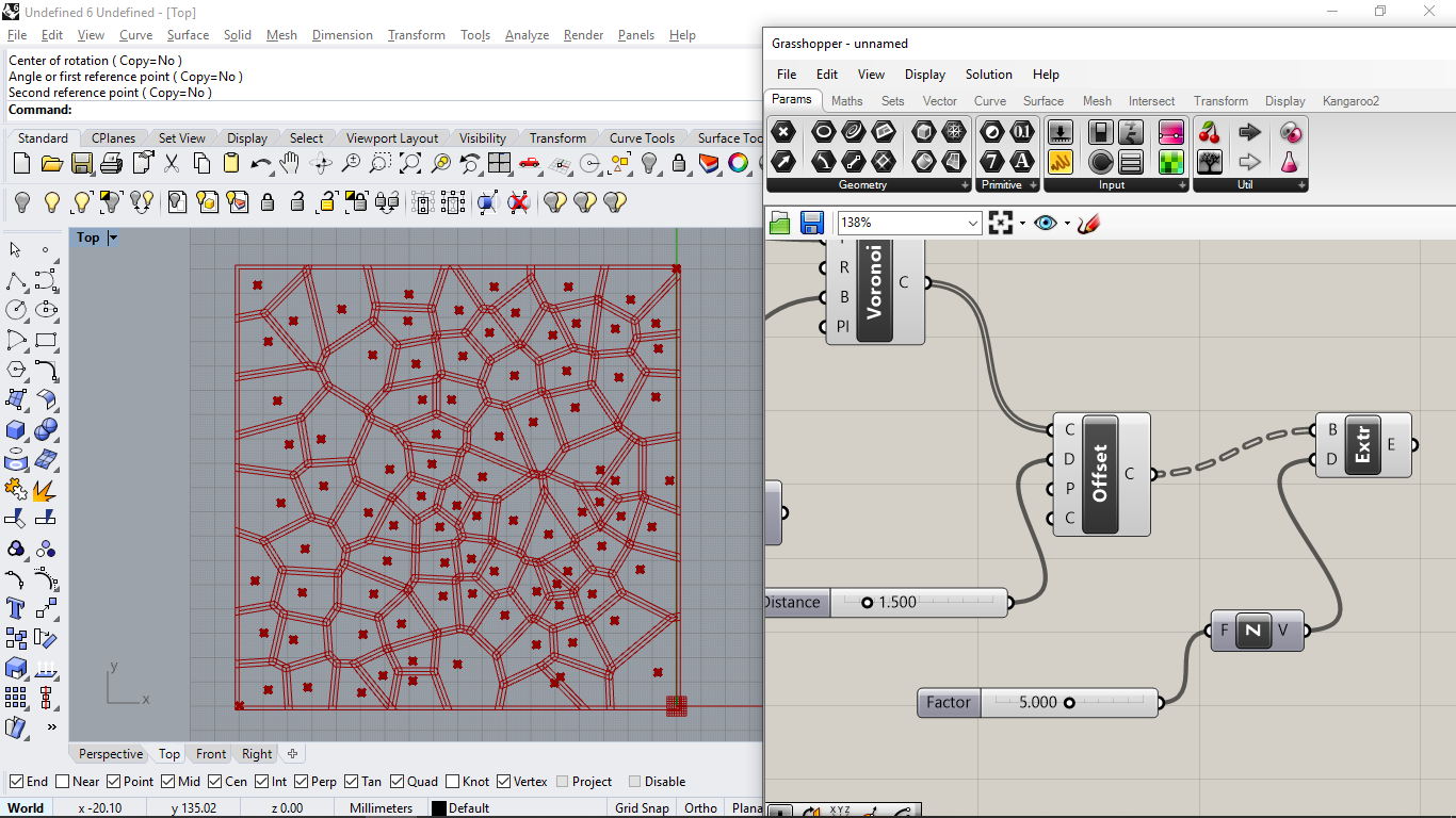
OFFSET TOOL
OFFSET TOOL will help us to generate patterns.
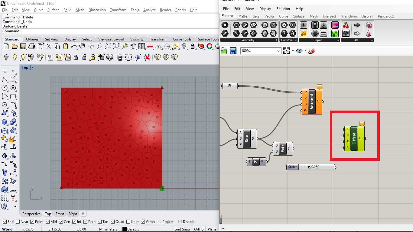
Connect offset with voronoi
By connecting Voronoi with the offset, you can see in the image, it will generate paths in the area.
Parametric relations
By using the Number slider tool, I can change offset factor in real time.
manipulate diagram with points
you can manipulate the voronoi diagram by just changing points location. you can move and rotate(with respect to a reference point) multiple points and select pattern whichever you like.
Add extrude comand
Add extrude command to the output of offset.
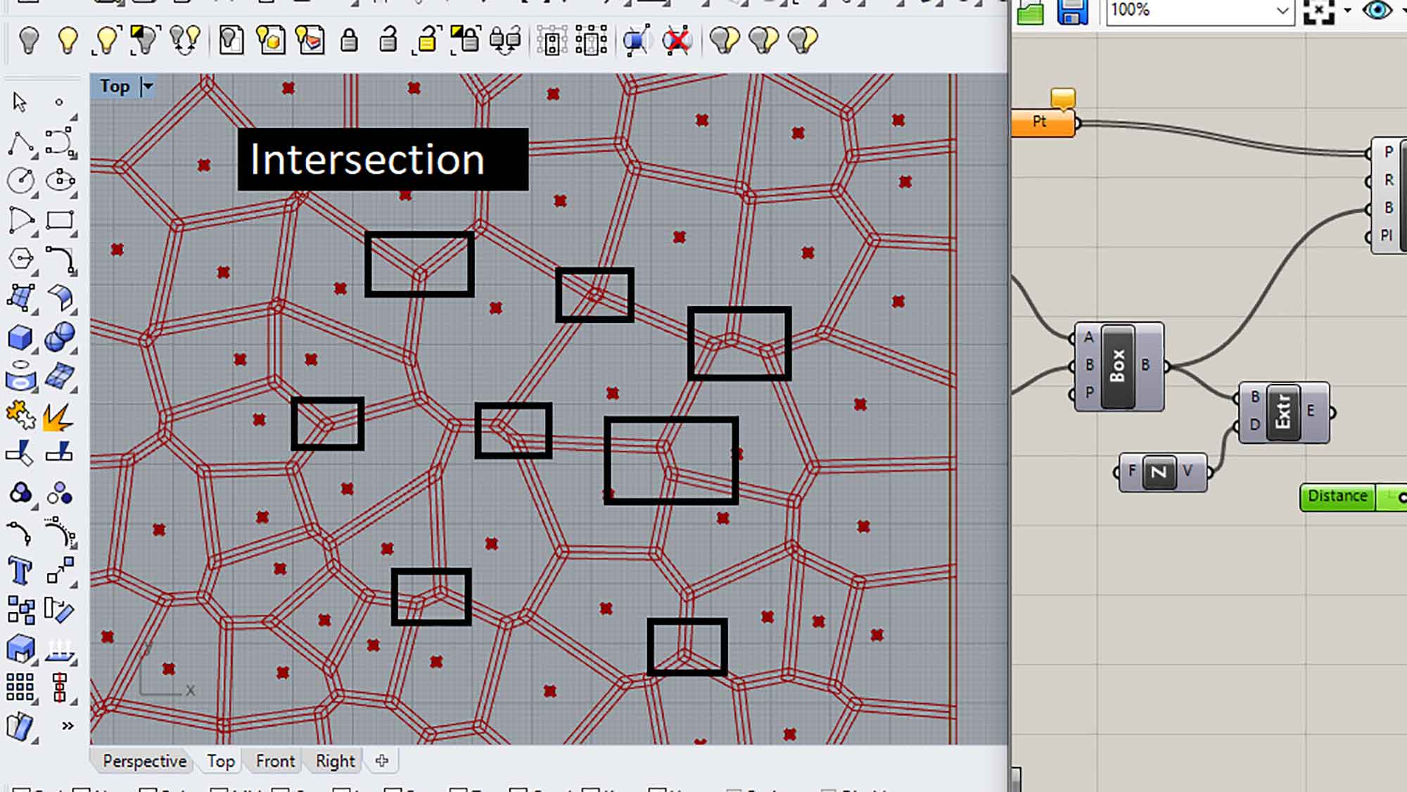
intersection
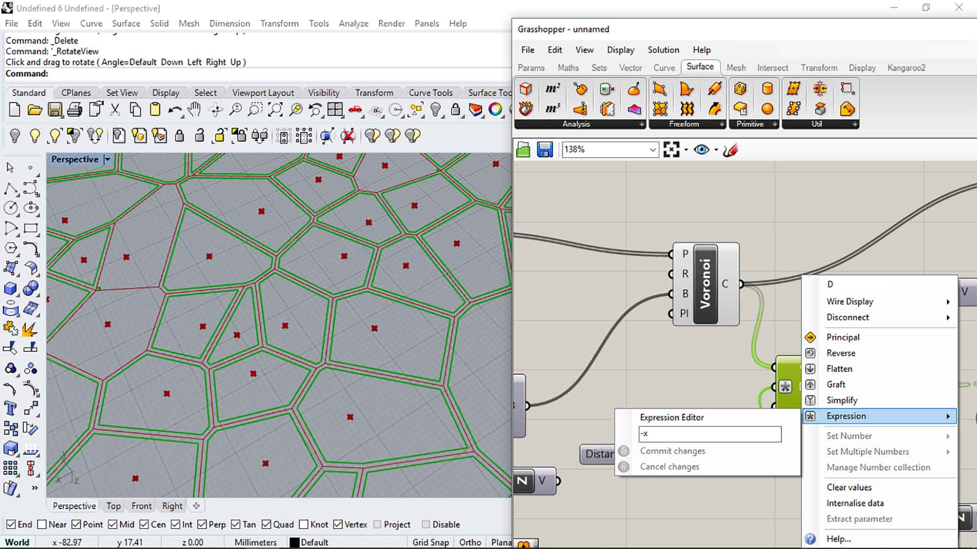
These are the intersections of offset, for the better pattern it should be eliminated. You have to go to expression tab of Offset mod to give the variable "-x". it will remove the intersection between the offsets and make them close.
flatten the extrude
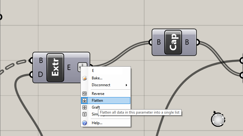
Right-click to extrude and select flatten. flatten is used to group the data in single entity. you can see the dotted wire coming in the input. it shows multiple data inputs (Brep). we have to convert it into single information(grouping them). that's why we use flatten.
cap holes mod
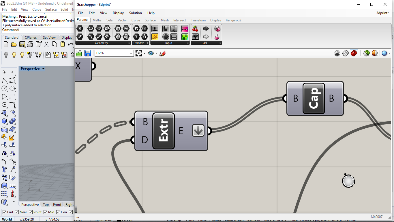
type cap holes in grasshopper which creates solids of enclosed regions.
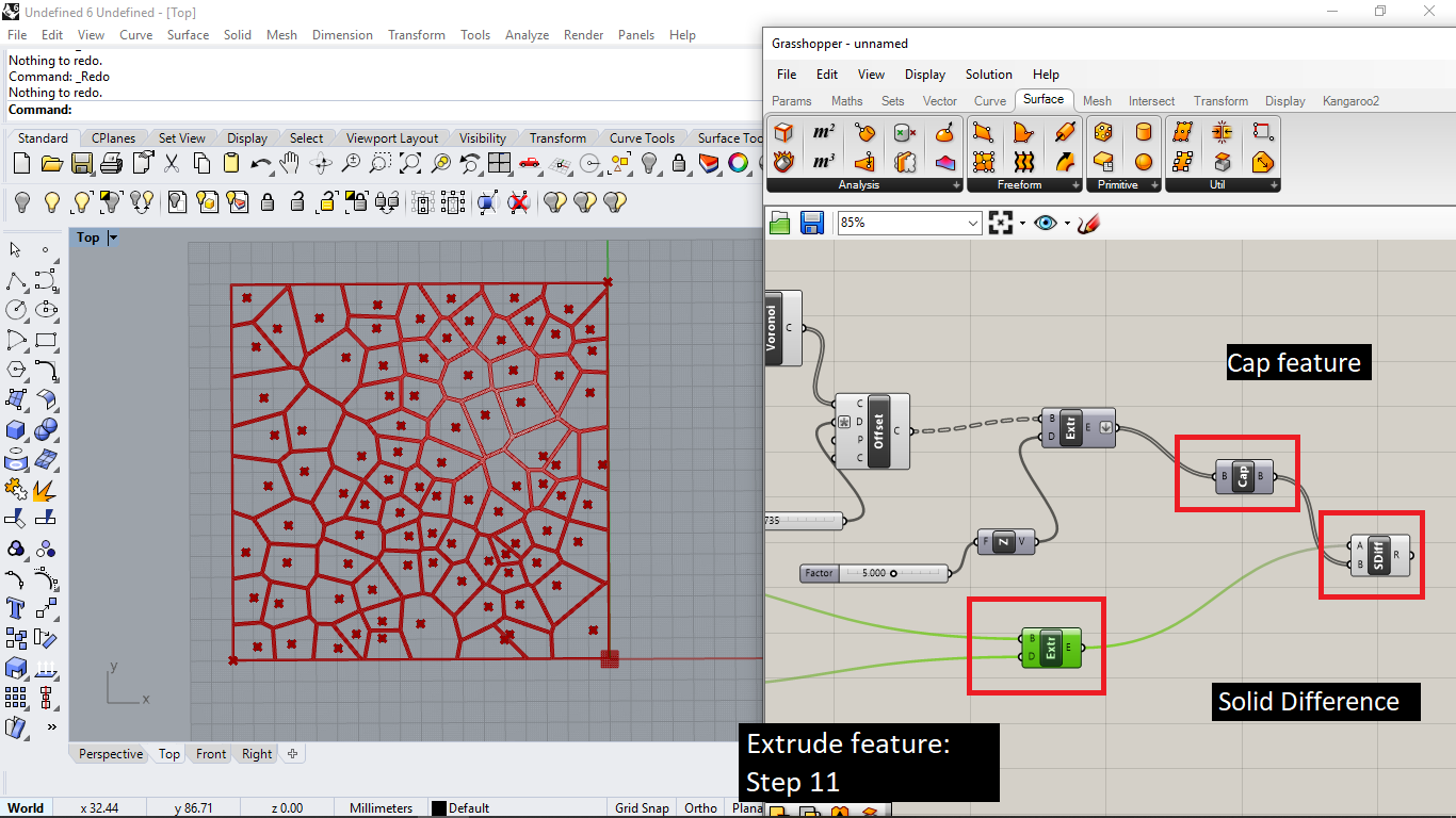
SOlid difference mod
Then connect cap holes with Solid difference. solid difference works as a union difference. connect Extrude mod (of BOX 2PT TOOL) to A point, and then Cap holes mod to
B points.
A = solid which is going to subtract
B = solid which will be use to subtract.
generate a rendom surface
Make a curve on Rhino with curve command. and extrude it with extrudecrv command.
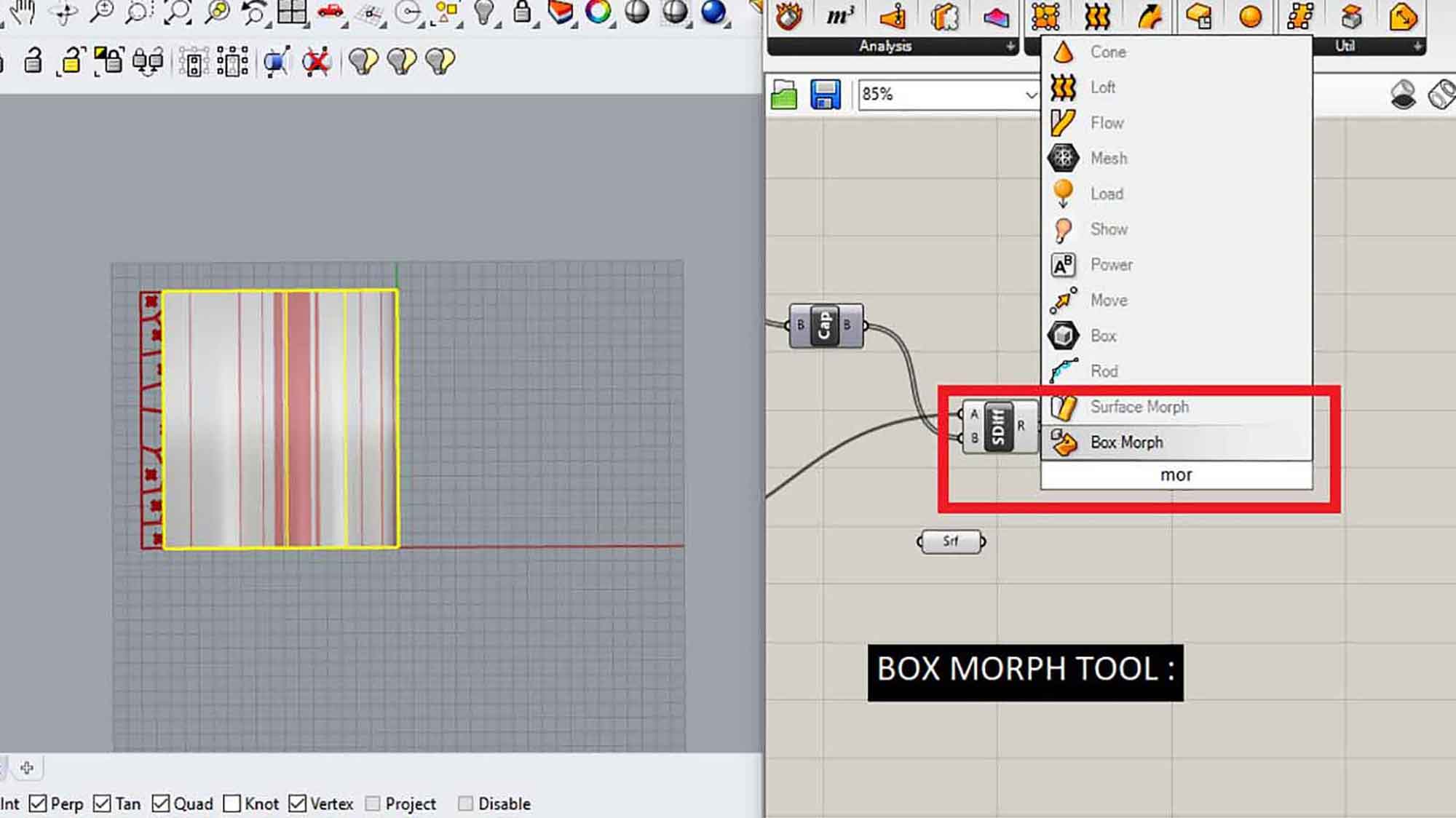
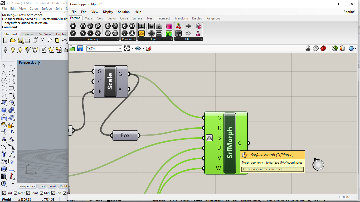
Surface morph
The surface morph tool, it will help us to align the pattern to the surface.
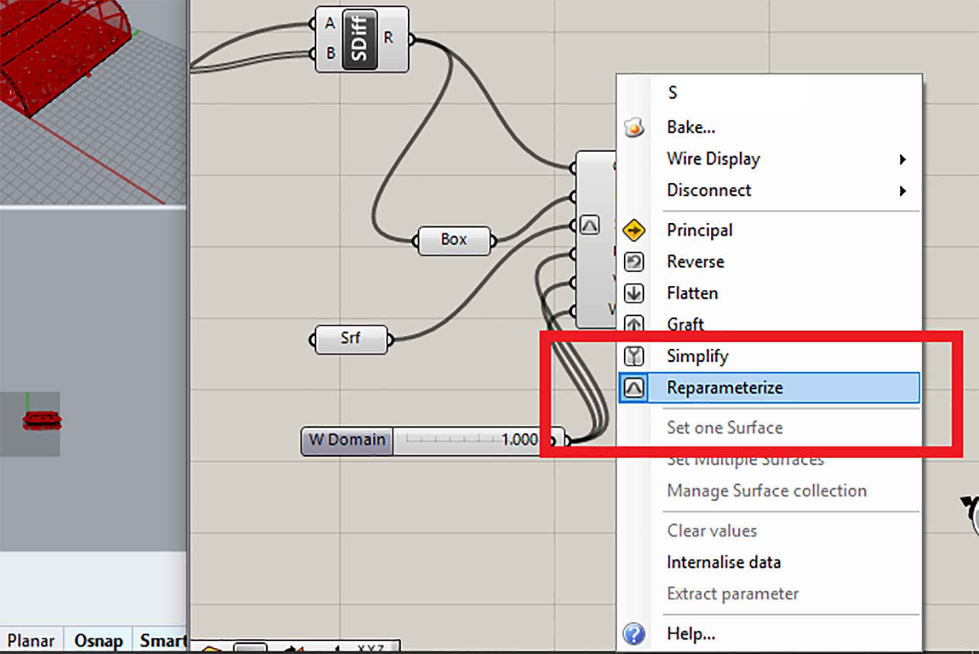
re-parameterize
Re-parameterize the surface, it will convert the whole surface into unit dimensions, means curves maximum length is 1 and the minimum is 0. Here longitudinal dimension is the U parameter and the transverse
direction will be V. W will be the amount of thickness you want to give on the pattern.
you can change U, V, W by Number slider. For U and V keep maximum value 1. Otherwise, the pattern will go outside the surface and it won't be a pattern.
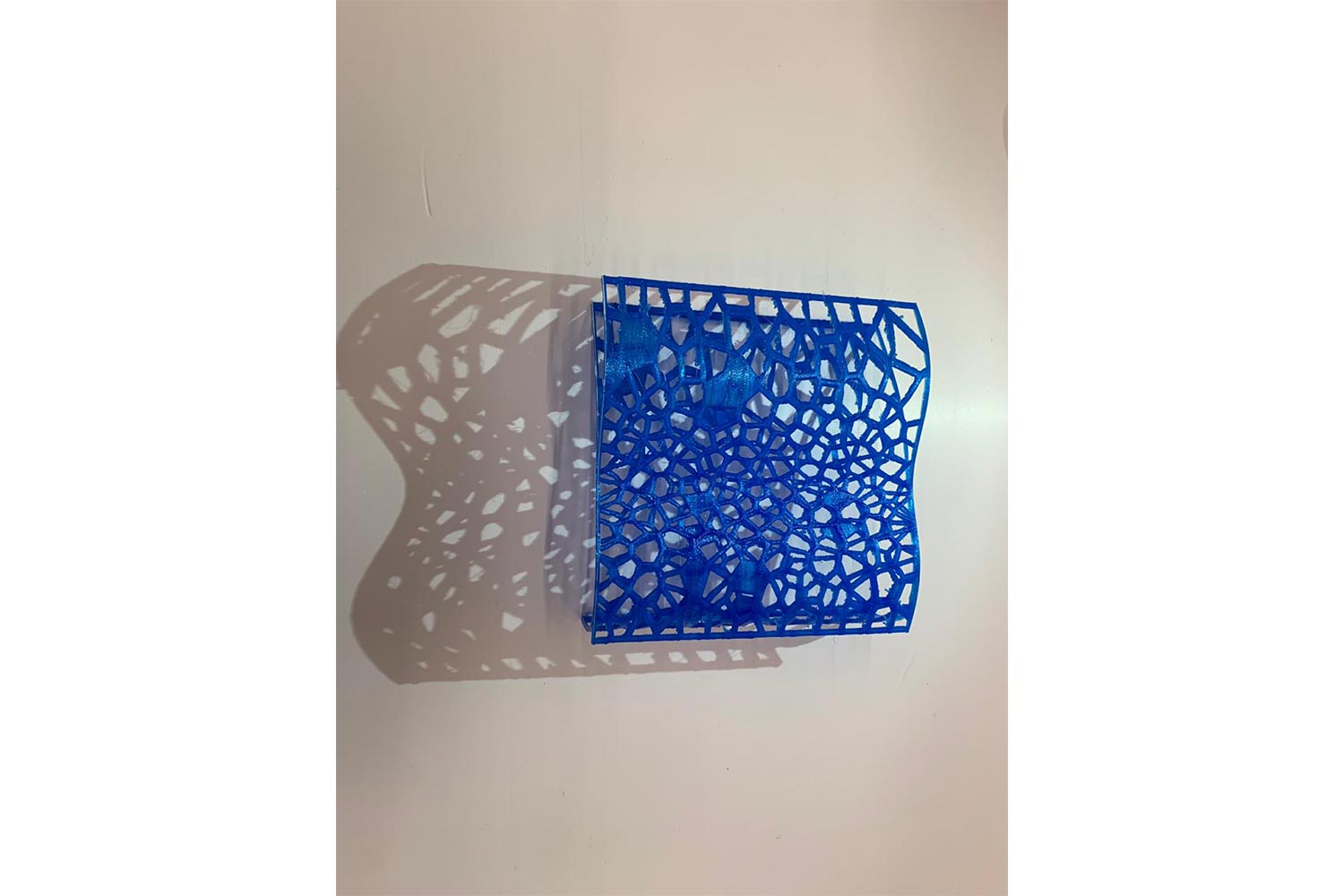
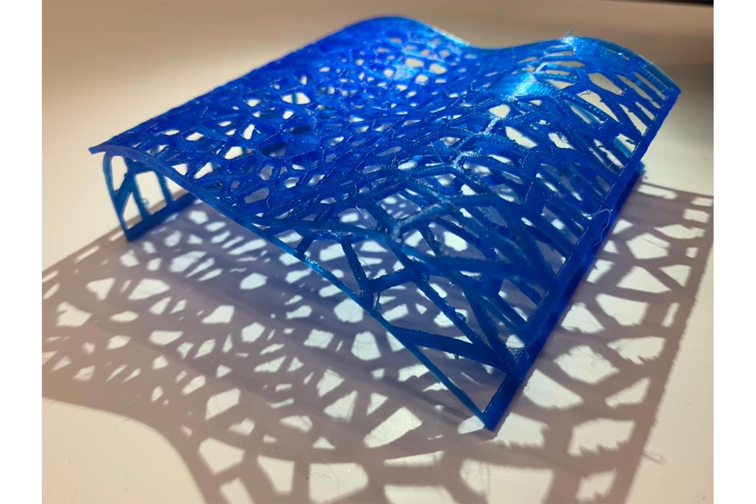
Final Product
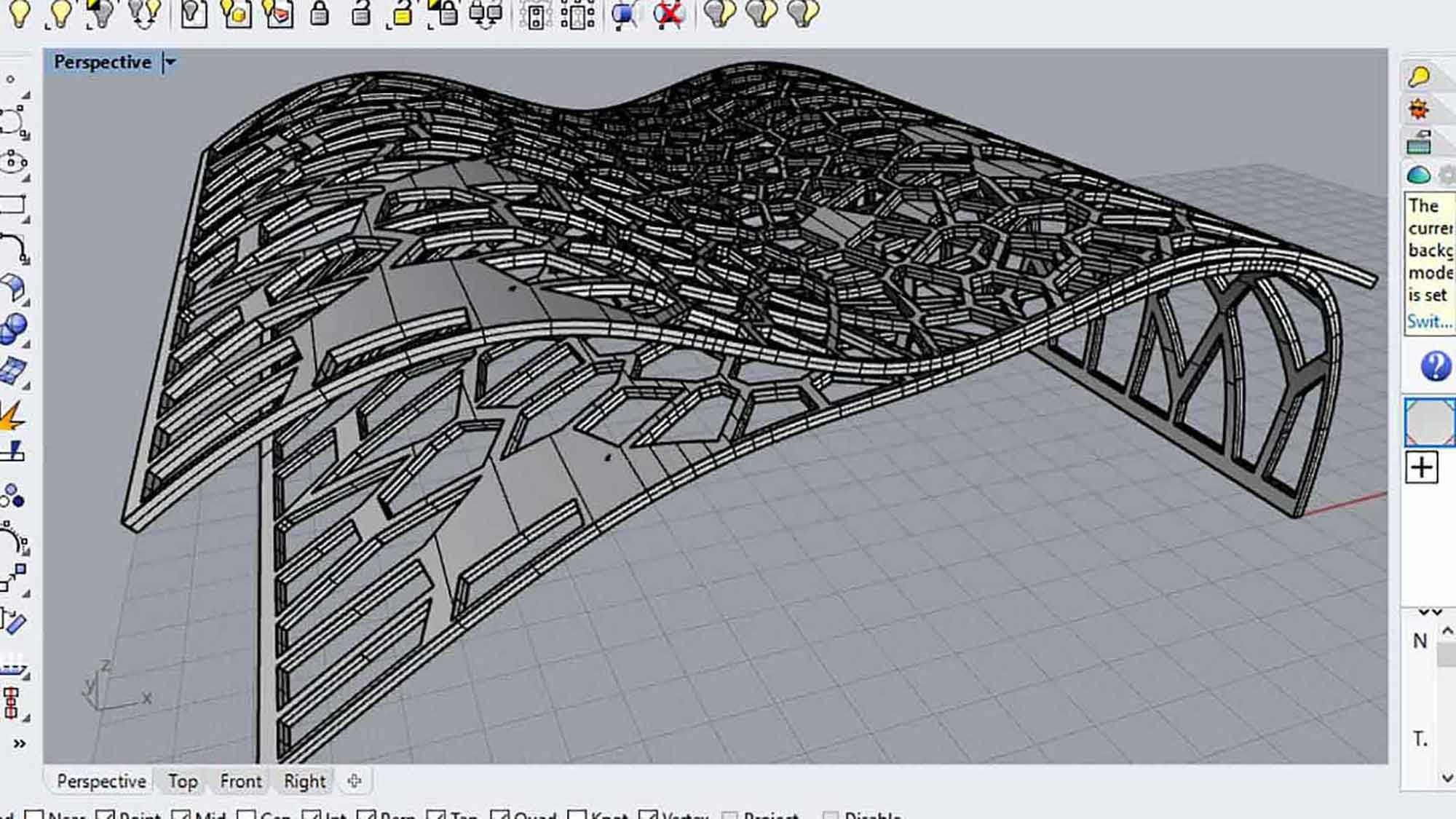
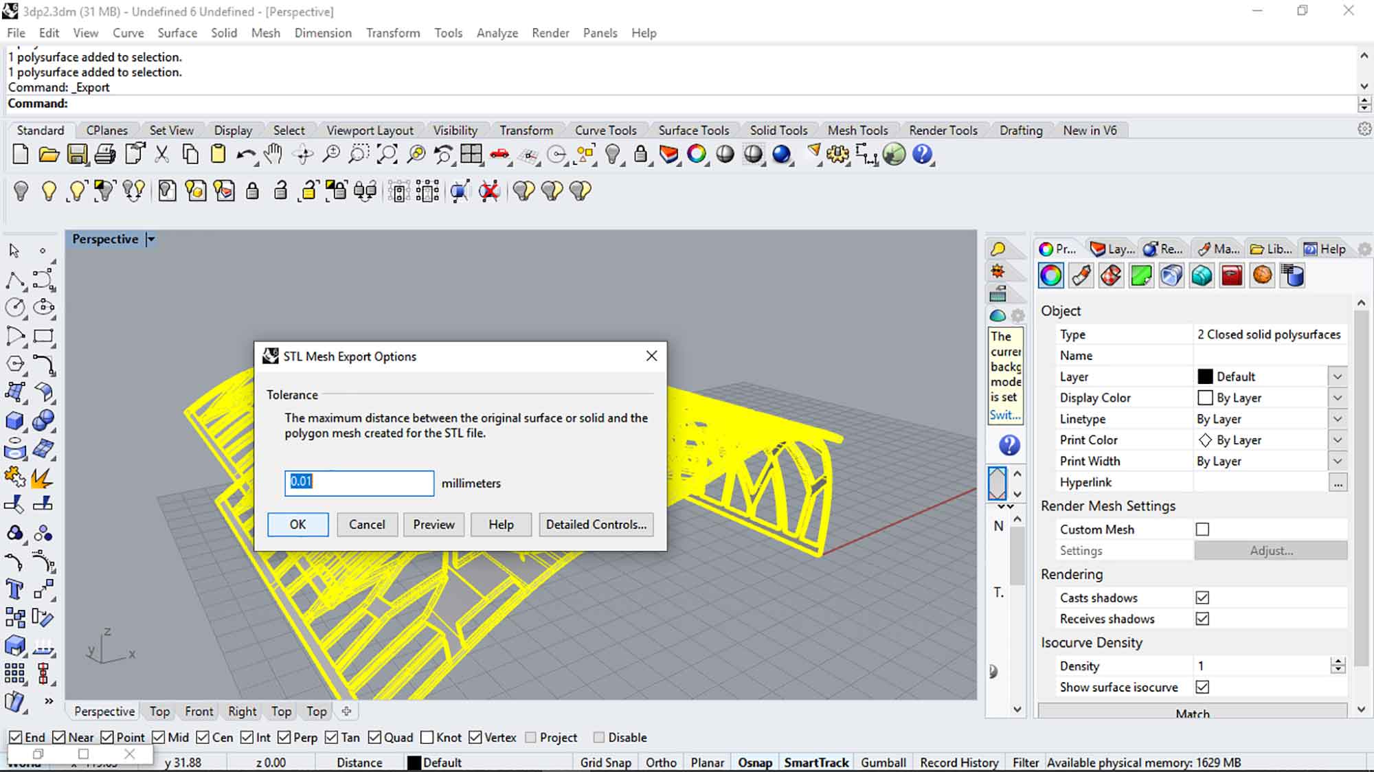
Exporting model as STL
.STL is used for the FDM type of printers. in which the 3d model is converted into layers and mesh which are used by the slicer tool.
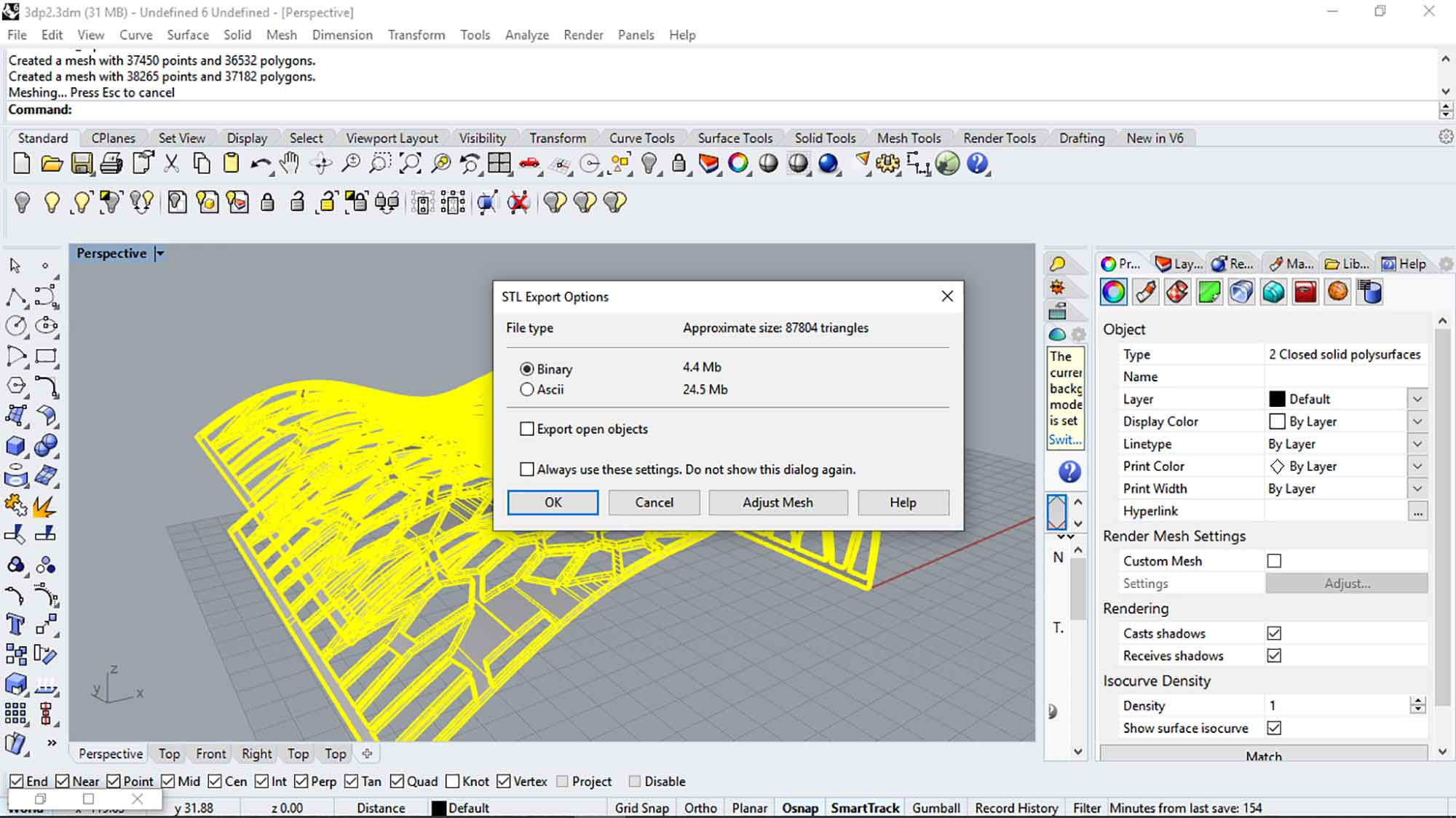
Binary and ASCII
There are two options for Export in .stl. Binary and ASCII, in binary you can't modify the 3d geometry after generating it into .stl in ASCII you can do modification and it is humanly readable I chose Binary for now.
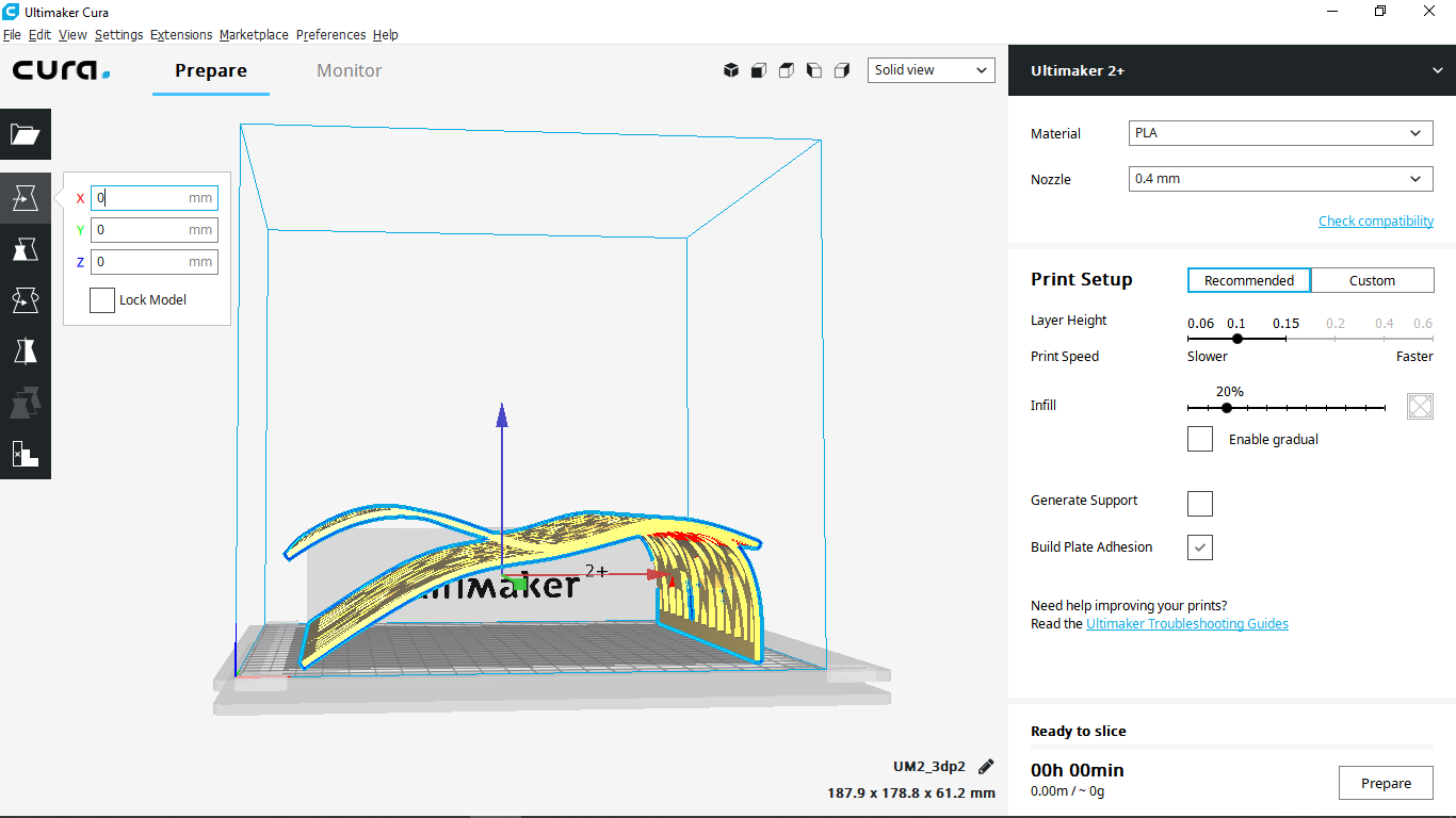
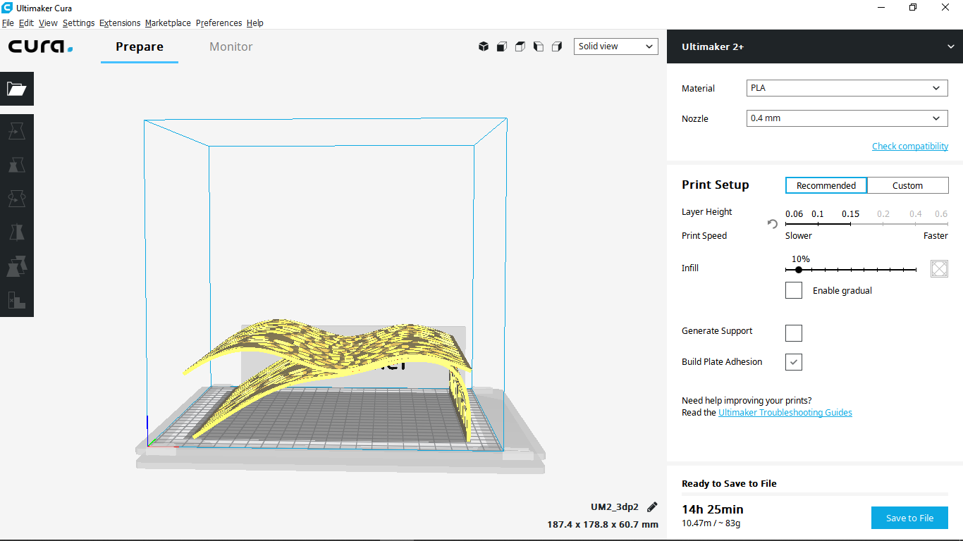
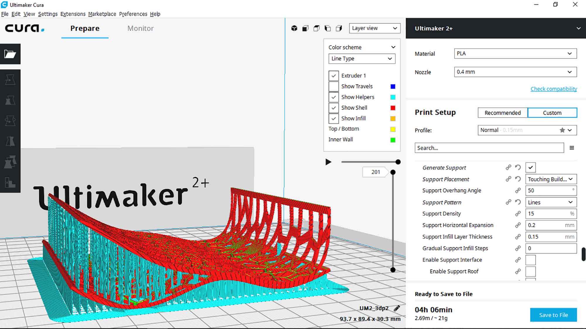
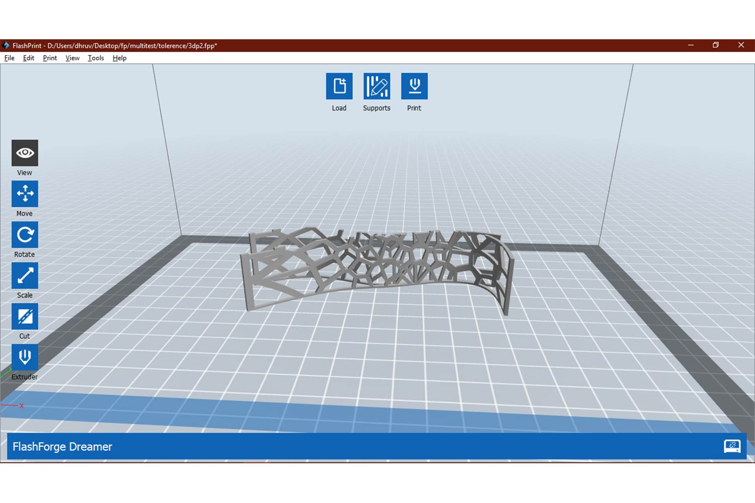
Slicer softwere : cura
Imported model in CURA
It is the first time I was going to use any 3D slicer software. we have two 3d printers Ultimaker 2+ and Flashforge Dreamer. I chose to use Ultimaker first. On default settings and size, print time was way too long, as expected.
I
do some changes to minimize it. I want to understand the settings so I started reading about cura's user manual. Click here to Download.
success in reducing print time
I was successful to reduce the time to 4: 00, but at a cost of quality and strength. To reduce the time I changes following settings.
To reduce the time of the print position of the object to be print, layer height and support play a major role.
Object position - minimum height if possible.
Layer height - max for less time and more strength
Support - orient object in a way that supports are minimum
Settings
Material : PLA

Scale-down the model to 50 %
tried different Orientation

Profile : Determines Quality
Normal = 0.15 mm

Quality :
Layer height : 0.2mm : more layer hieght less 3d print time and less quality

Infill :
Infill density : 10% : Infill stands for cavity area inside the walls
Lower the infill lower the printing time weaker the job

Speed :
outer wall speed : 60 mm/s : Print speed of outer walls
Inner wall speed : 60 mm/s : print speed of inner walls
TOp-bottom speed : 50 mm/s : Top-bottom wall speed
support speed : 55 mm/s
Travel speed : 200 mm/s

Higher the speed lower the time and bed printing quality

Enabled Acceleration. : It will accelerate the nozzle while travelling , reduces the time and effects retraction

Retraction : Retraction is ability of nozzle to retract or suck the material in when printing is not
needed.

Enabled Jerk control : Controls the jerk

Support :
Support placement : Everywhere : Supports overhangs
Support pattern : Grid : Depends on printing model
Support density : 12 : how much area it will cover

Build plate adhesion :
Build plate adhesion : Raft : for giving support at Build plat, to make the model attached to Build plate
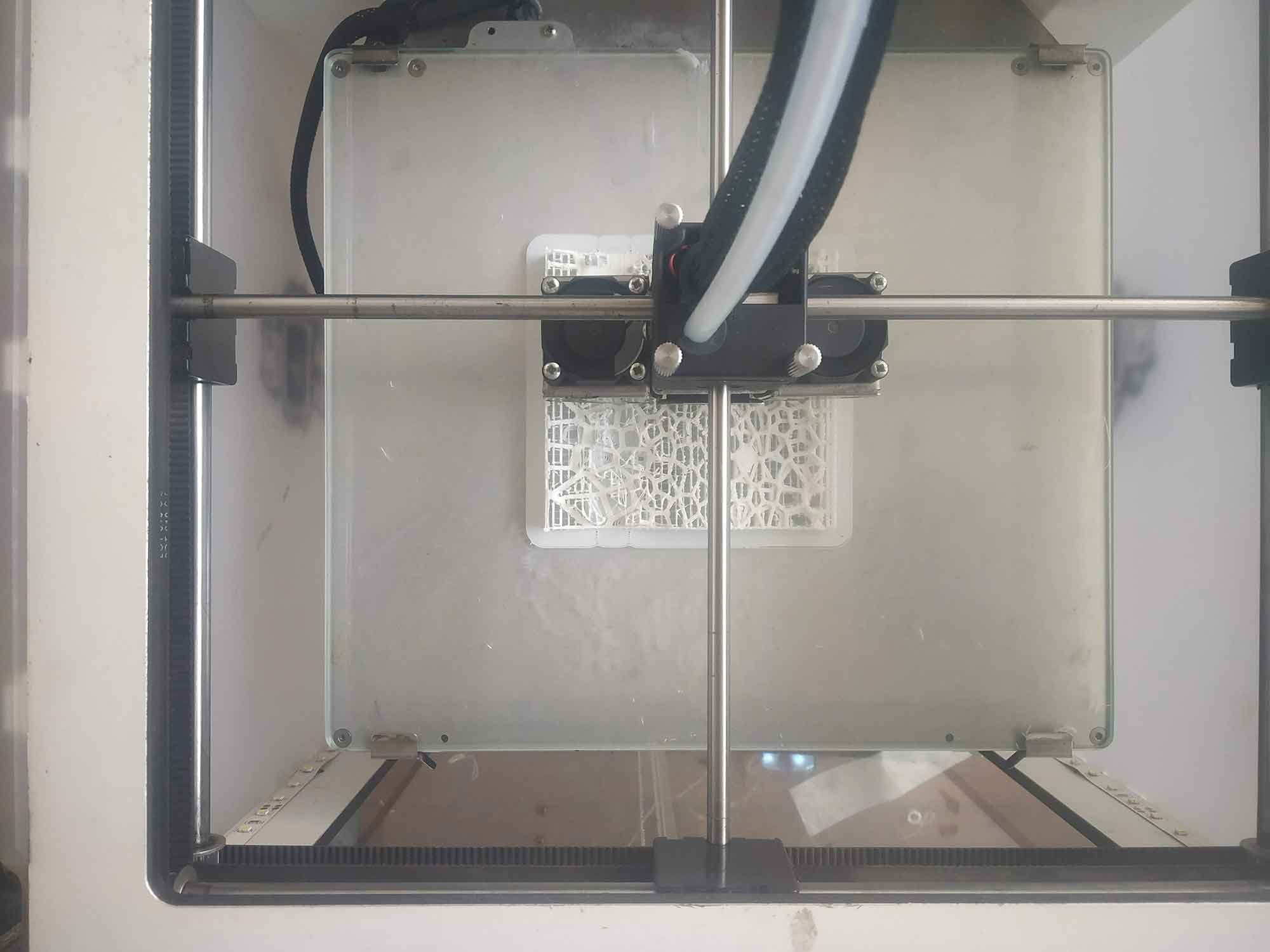
STARTED PRINTING
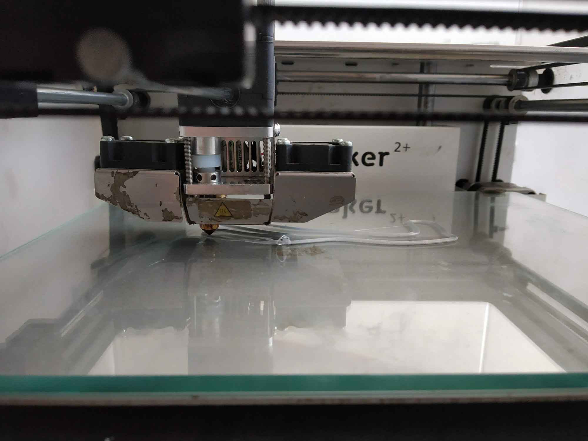
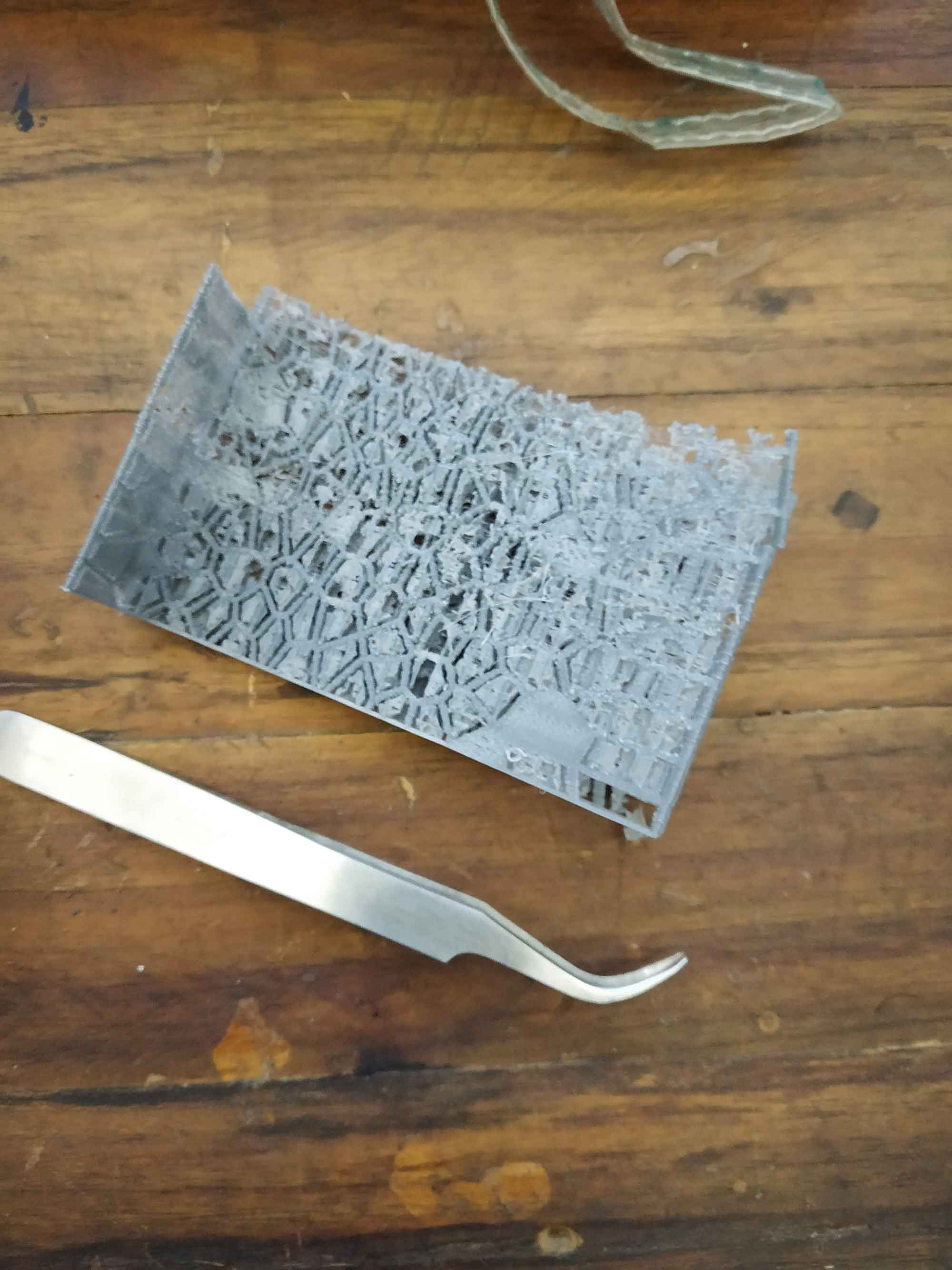
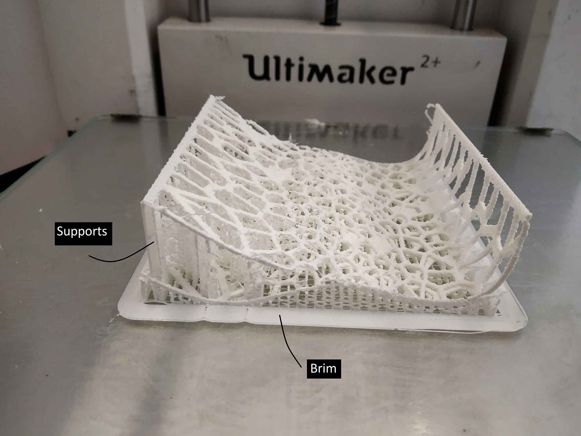
STEP 18 : FINAL OUTUT
It came out good but not the way I expected. Since I have to reduce the time and doing it the first time I mad the structure weaker and Adding more, 3d printer stopped material drawing 90 % of the job, so I have to take out uncompleted print.
BREAKING APART SUPPORTS
It will not work, I Broke it!
conclusion :
I try to find which mistakes I have done in settings parameters :
- Layer height - can be less for this types of thin designs.
- Infill - it is important factor, I put infill 15% (only 15% of inside will be poured with material). It is not appropriate for this thin complex bodies.
- Orientation of the design - the way I put my design it took more time to print.
- Speed - I kept Print speed high. it Decreases the quality and that's why surface was ruff.
- Wall thickness - I kept wall thickness low which should be more to better overlaps of design.
- Supports - I put wrong types of supports in my designs, I found out when I removing it, Grid supports are not so good for these types of designs ( Complex Voronoi). line supports are preferable
- Supports location - Where I put support is more important, if I put support on the body itself it will stress the body itself and try to break it if the body is thin.
Second Try
I change some settings and tried one more time. changed settings are shown in red I also learned some basic, "Always give your model first priority, think about its strength and quality first. after setting up required value find ways to reduce time"
Material : PLA

Scale-down the model to 50 %
tried different Orientation

Profile :
Normal = 0.15 mm

Quality :
Layer height : 0.15 mm

Infill : I increase the infil to give the strength
Infill density : 80%

Speed : I lower the speed to increase the quality and strength
print speed : 50 mm/s
outer wall speed : 60 mm/s
Inner wall speed : 42 mm/s
TOp-bottom speed : 50 mm/s
support speed : 55 mm/s
Travel speed : 80m mm/s
Acceleration : Disabled
Enabled Jerk control

Support : I change the support type to lines for better removal
Support placement : Touching build plate>
Support pattern : Lines
Support density : 15 %

Build plate adhesion : I change from raft to brim because it takes lower printing time and still good bed support
Build plate adhesion : Brim
Brim width : 6 mm : its a width between initial layer and outermost brim count
STEP 20 : Second file
I change the orientation and settings, hopefully, time was the same.
Ultimaker
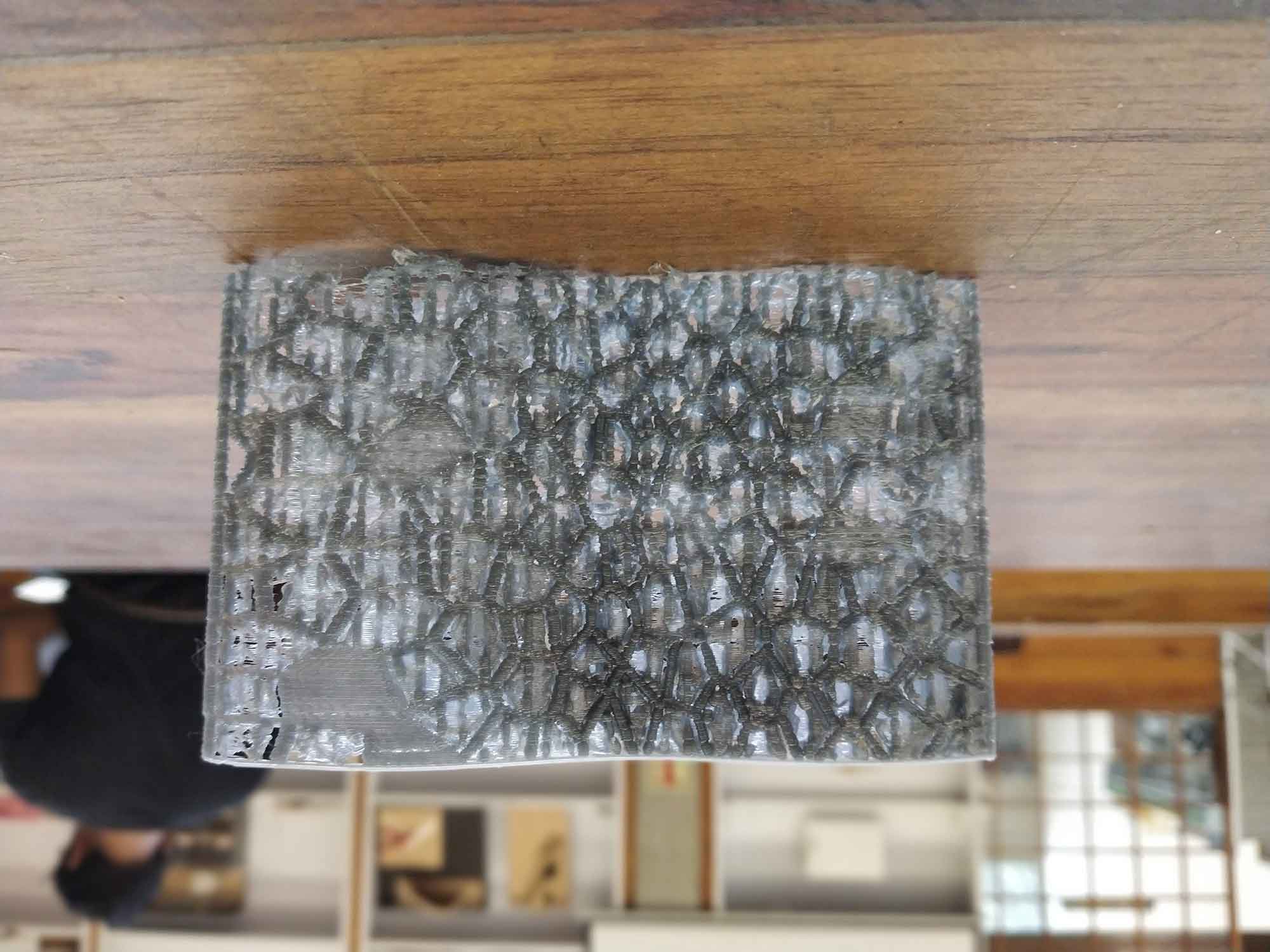
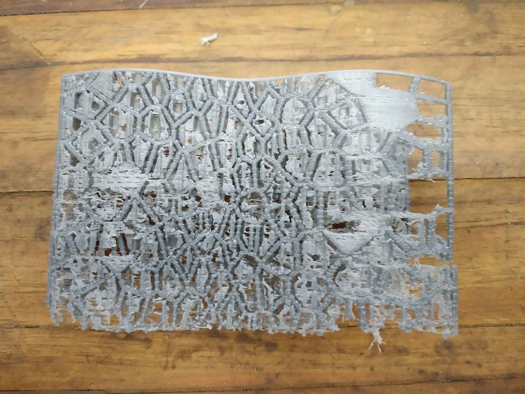
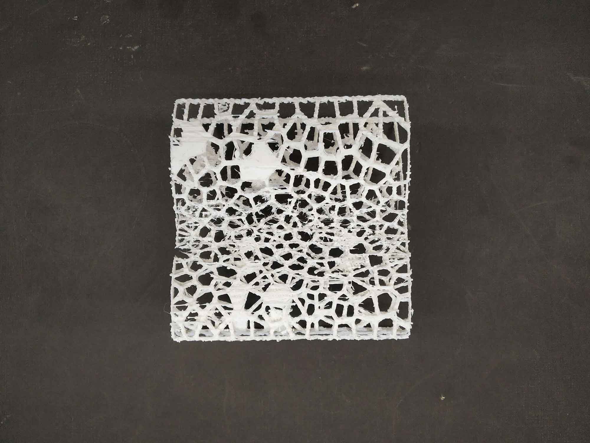
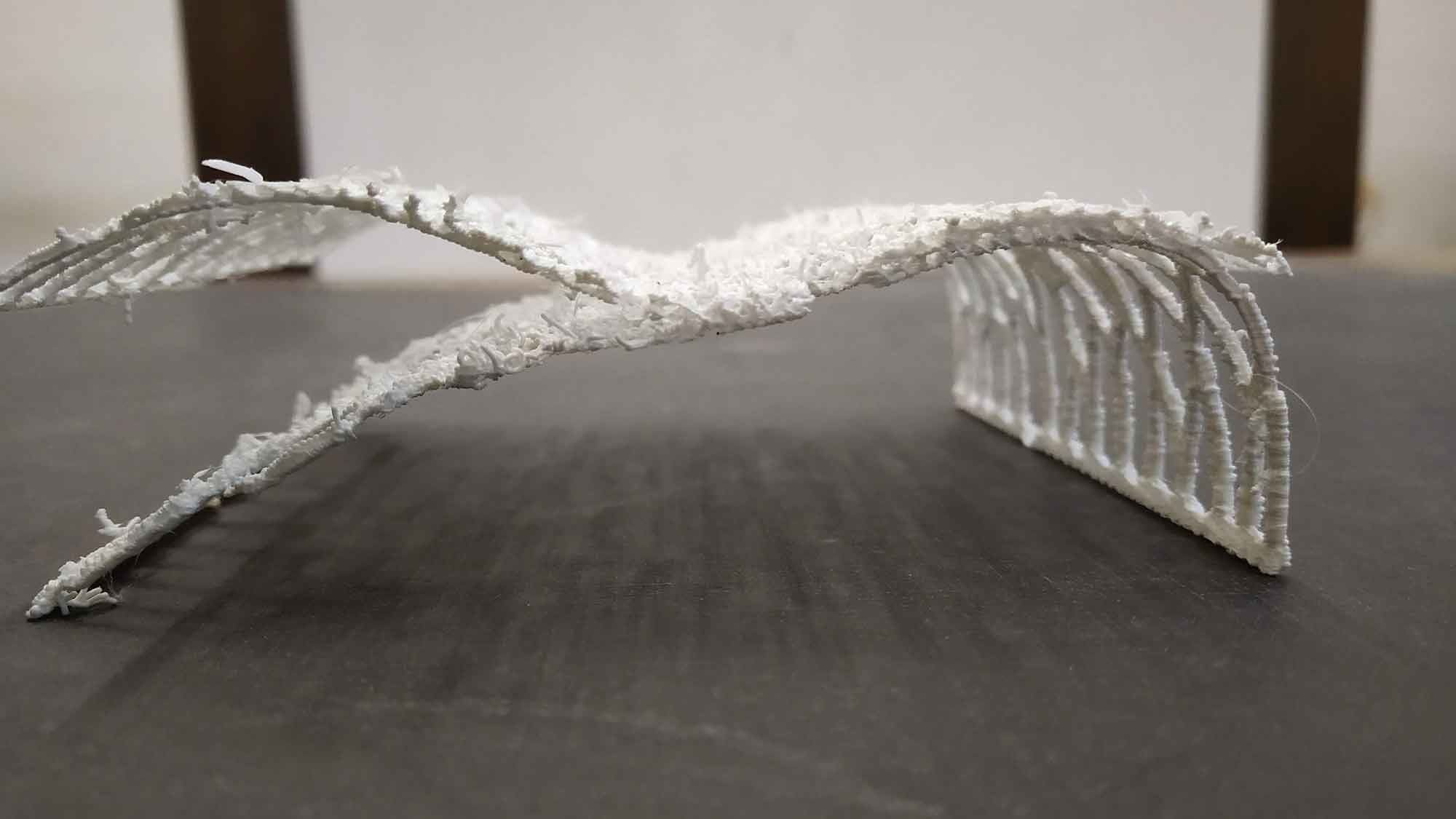
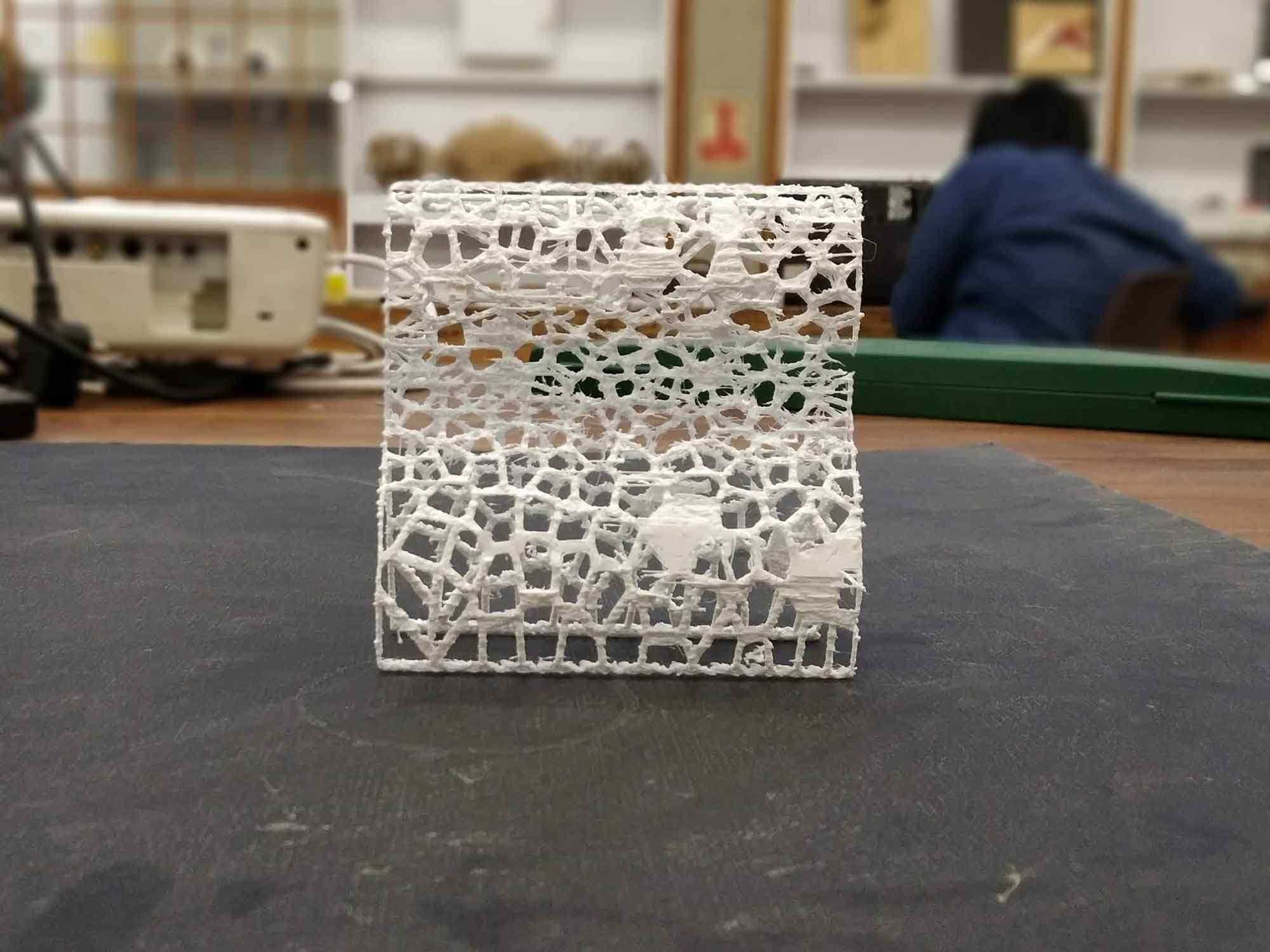
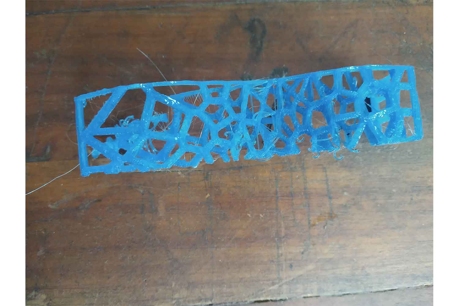
Final Output
It came out bad, I managed to give some strength to the model but quite fail to give a good physical appearance, for now, I have to smooth it. 3d printing is not just plugged and play for sure, many things should be in
consideration, in the second model I found two layers are not printed well because of overhangs, but still model has Good strength and flexible also!
This design is not complete yet, I am going to do some iterations, for now, experiment with design and come with Final OUTPUT in Ultimaker. since I found the printer also needs some maintenance I moved to our second printer flash
forge.
Flashforge
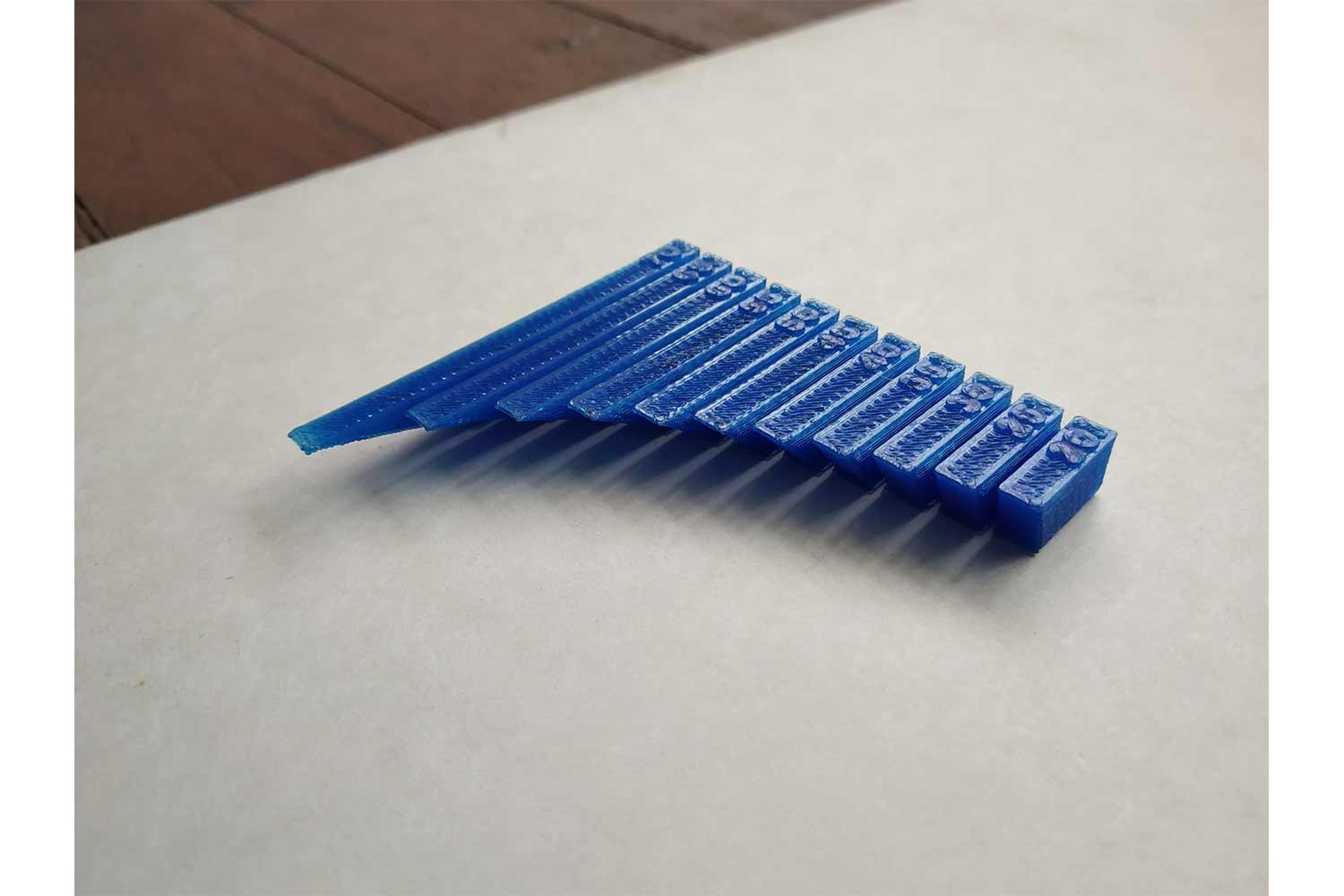
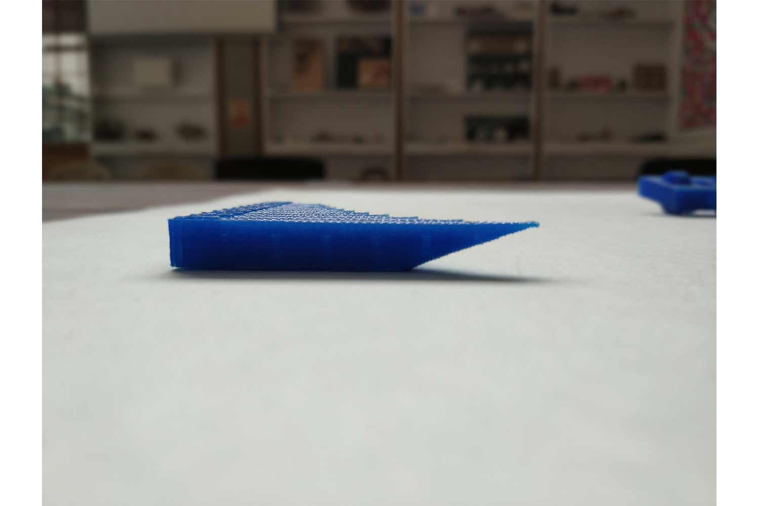
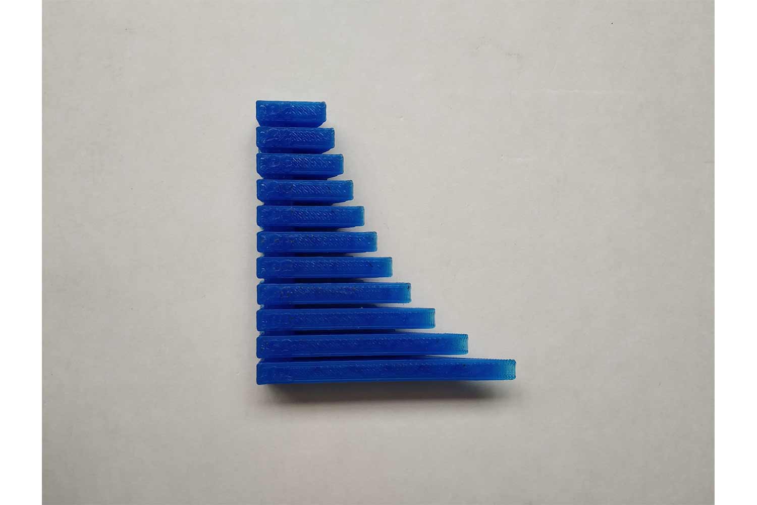
I was also printing my model with flash forge, so I can have design limitation of both the printers, in the flash forge I can go up to overhangs of 70 degrees. I came to this conclusion by doing some limitation tests on the
flash forge as part of our group work. below are some pictures of the overhang limitation test it prints fine up to 70 degrees and I think it can go straight to 80-85 degrees.
But I didn't want to make it so easy for the flash forge to print my model, so I decided to print the model without supports. I took one sample of my design and tried different Orientation, Speed, Temperature to make perfect G-codes for
design. I was using flash print software for generating .gx file.
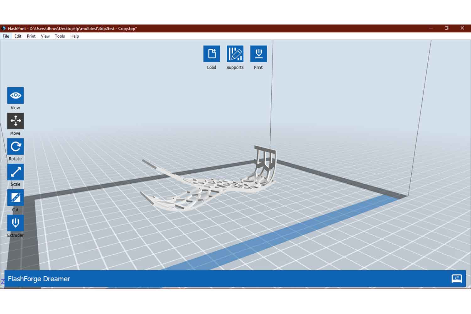
first orientation
I was quite sure most of the overhang will work fine but Want to know which part remains week comparatively, so I can give manual supports there.
in flashforge
Output
The results are really good and I was sure I can print this model in this orientation without supports, only the Critic side is that end overhang which can be managed on post-processing.
Different orientation
I tried with different orientation this time, time was 30 minutes less, but there was a problem, Raft was not sticking to the print bed, so increased the bed temperature( up to 60 degrees) and nozzle temperature( up to 210 degrees) also.
Very strong Raft
One thing I don't like in print is a very strong raft. yes! raft or brim is necessary for the support of the model, but this was a headache, it bonds so strong with my model that it tears of my very first layer of it, to resolve it I opened expert mode in preference and change Z offset to 0.4 mm. Hope it help.
STEP 27 : Output
I think the increasing temperature was a mistake. Due to that, I found retraction problems on output material was not solidifying as quickly as it should be. in bridge side material got separated a little bit, it is supposed to be clean
as per the overhang test (Reason can be Low print area and Temperature factor. I have to try a second time with low speed and suggested temperature. this orientation reduces 39 minutes of my sample, so it will
definitely benefit me in the full model
none of the above parameters help me here. I had the same retraction issues there, so I went for the first orientation.
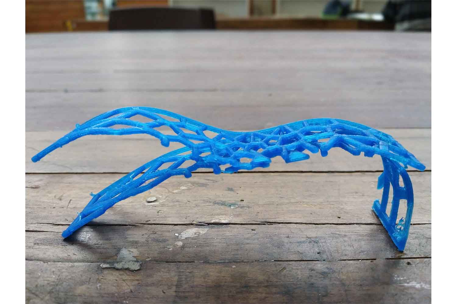
final 3d print model
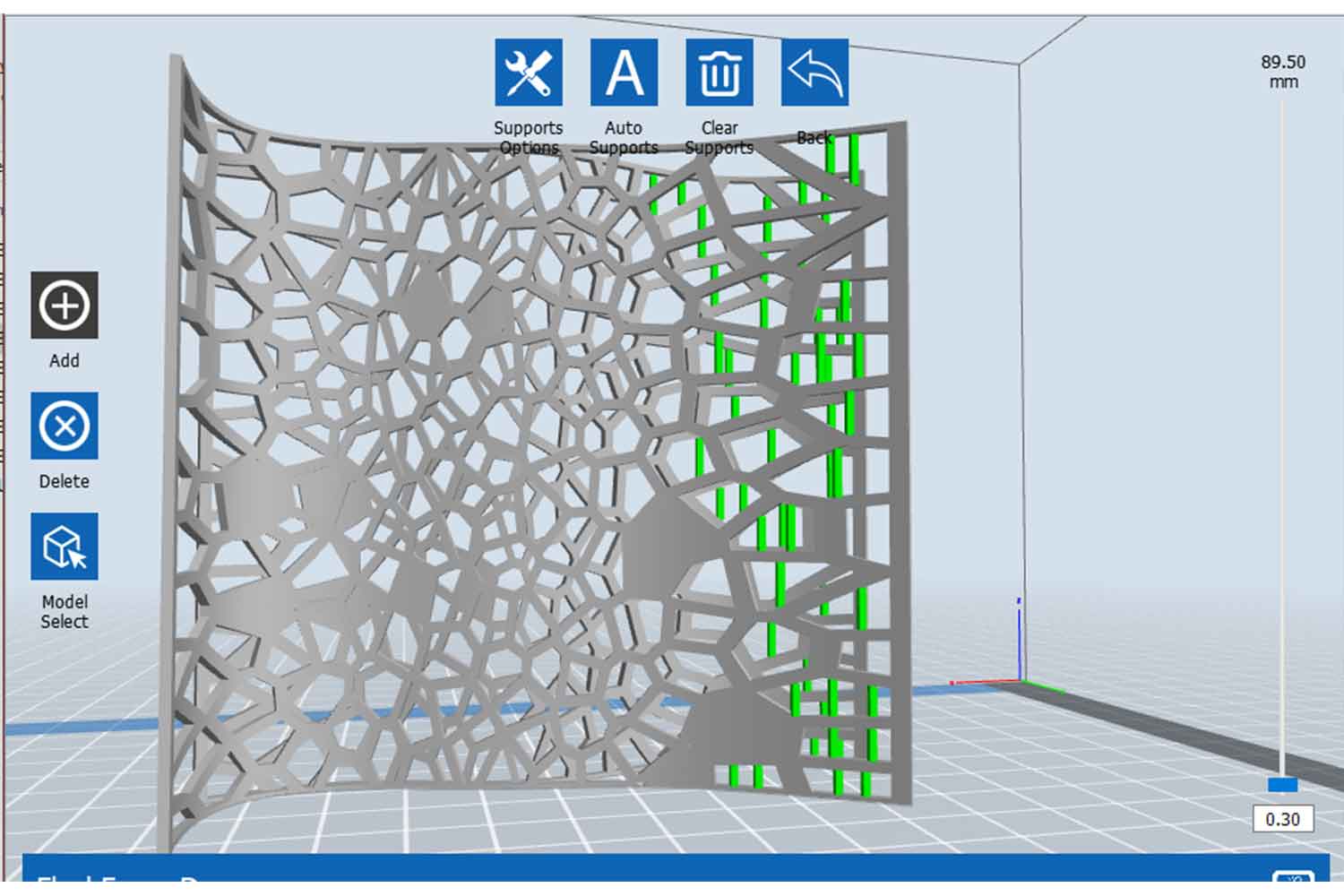
Knowing my first orientation will be good for my final design, I went for a full-scale model. on the full-scale model since I know which will be critical positions for supports I went for the Manual supports in the
model.
I gave the supports two sides, At the curves and at long bridges at the corner.
At corners
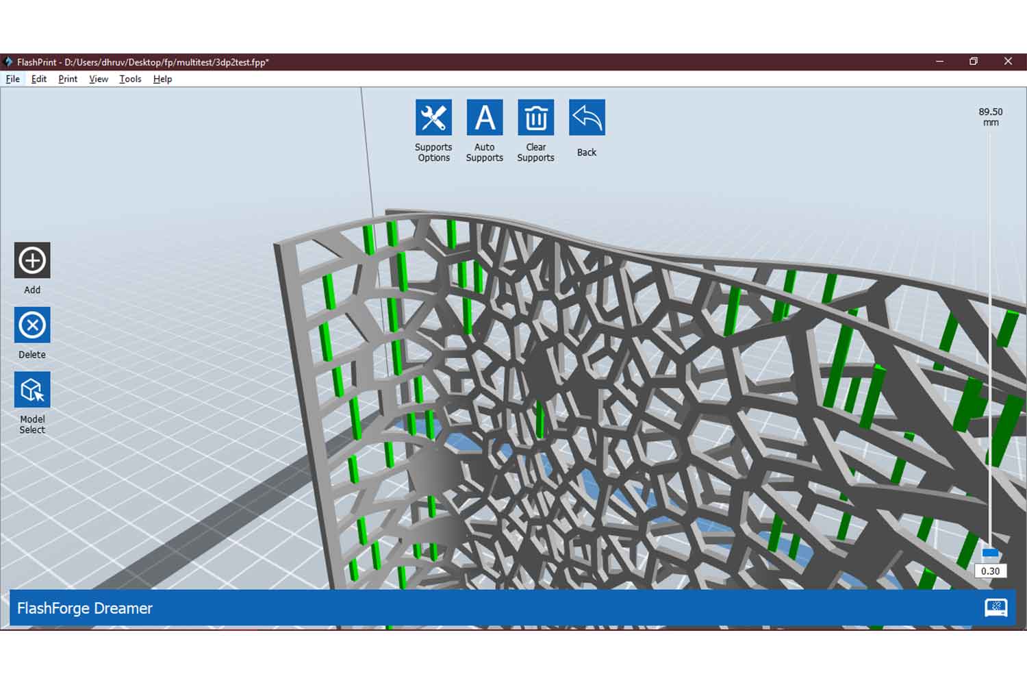
At bridges
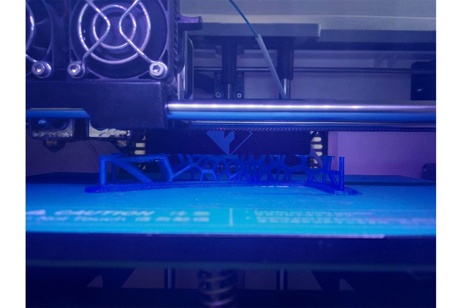
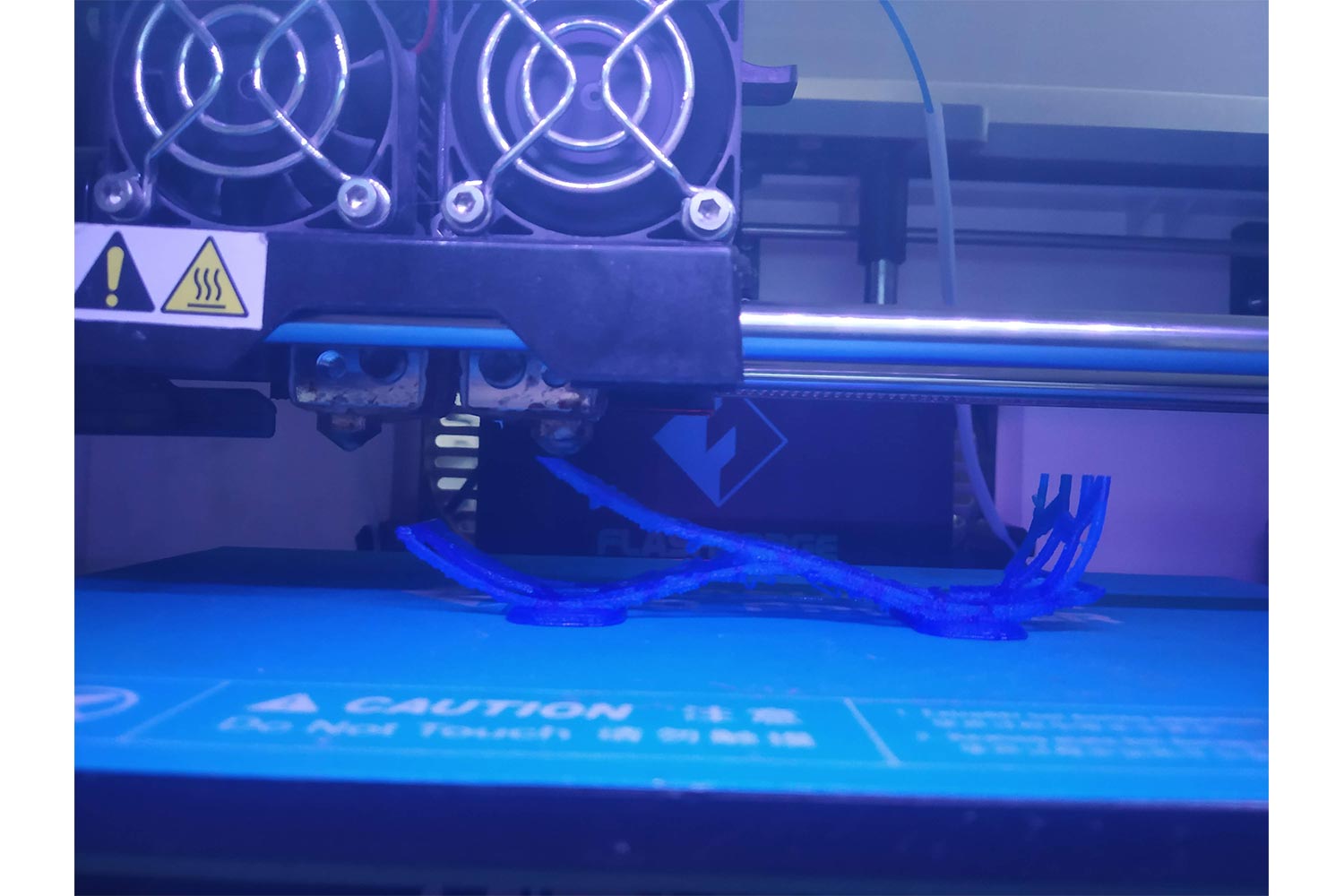
Printing
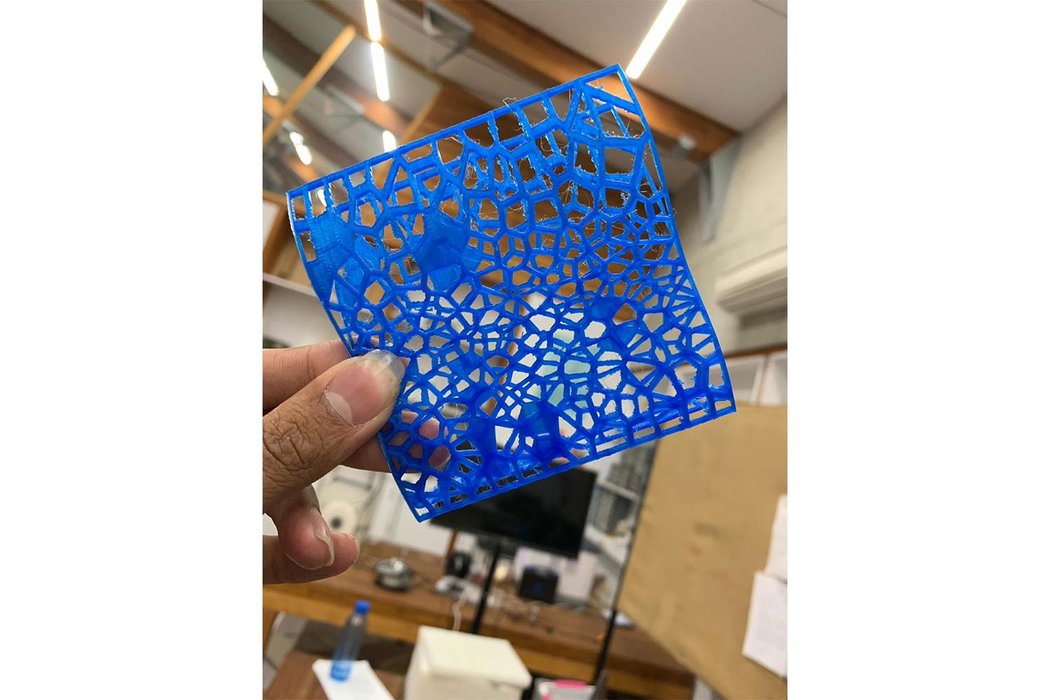
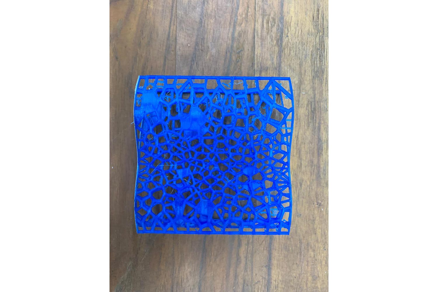
Final Images
I Love this picture. I never thought without supports it will be possible. all credits go to the printer.
3D scanning
3D Laser Scanning is a non-contact, non-destructive technology that digitally captures the shape of physical objects using a line of laser light. 3D laser scanners create “point clouds” of data from the surface of an object. In other words, 3D laser scanning is a way to capture a physical object’s exact size and shape into the computer world as a digital 3-dimensional representation.
Types of 3d scanning
Photogrammetry
Stemming from photography, photogrammetry is an incredibly useful technology in various fields. The technology takes multiple images, taken at different positions, and triangulates points in these images to figure out the location of them in a three-dimensional space. For example, land surveyors utilize this technology when making maps. When dealing with inaccessible places, such as mountains, the surveyors are able to use photogrammetry to perform their measurements. Many modern technologies use photogrammetry, the major determiner in precision relies on the caliber of the images. If images are poor, there will be holes in the mesh. The more images that you can produce, the greater the accuracy of your scan will be.
Structured Light
The technology here is created by casting geometric patterns onto an object while simultaneously taking images with a camera. When doing so, the camera logs the deviation of the image. Based on this displacement of the pattern, locations of all existing points are able to be determined. Numerous scans have to be conducted from different positions and then combined until the mesh can be 100% complete. Computer programs automatically combine all of the scans to form this complete mesh. The results formed using structured light 3D scanners are extremely precise, and the technology is available in both portable and stationary scanners.
Time of Flight (TOF)
Slightly more scientifically oriented are Time of Flight (TOF) 3D scanners. These scanners measure how long it takes for a laser or infrared beam to be reflected back to the scanner, with the main component in the scanner being the speed of light. Although the scanners contain highly accurate sensors, the precision of these devices is relatively low, ranging in centimeters. This is primarily a result of how the speed of light is affected by various factors, such as temperature and humidity. Hence the technology is primarily used in measuring large items like buildings. The technology requires multiple scans to be conducted in order to form a complete mess, just as with other 3D scanning technologies. The majority of devices using Time of Flight can be found in portable scanners.
Laser Scanning (Triangulation)
Perhaps the most accurate 3D scanning technology is that of laser scanning, also known to as triangulation. Similar to structured light and photogrammetry scanners, laser scanning uses the same base principle of geometry to find a point’s location in space. By casting a laser beam upon the object being scanned, a camera is able to record where the beam and object intersect. Knowing both the angles of the laser beam and camera makes it possible to know the precise location of the laser dot that is hitting the object. The accuracy of laser scanners is exceptional, ranging in mere micrometers. The only downside to the scanners is the fact that they can only range in just a few meters and the technology is typically not found in portable scanning devices.
Contact
With a self-describing name, contact printers physically touch a resting object. The scanning process can be fairly timing, and the process is very sensitive to movements and vibrations during scanning. Contact scanners are primarily used
in quality control due to the potential alterations that they cause to objects being scanned. The technology is not used in the conservation of objects as a result of this.
This content is from 3D Scanning services website.
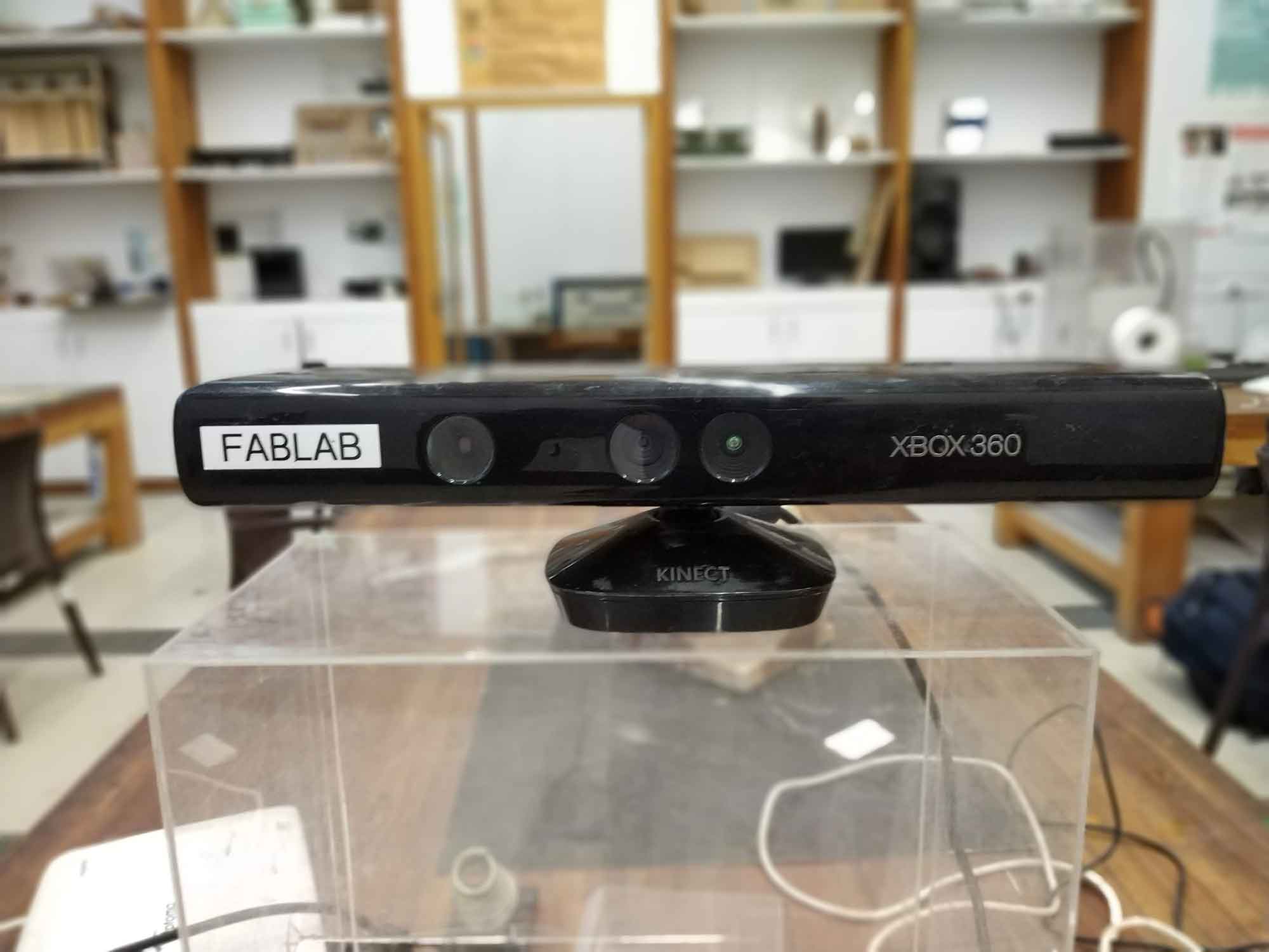
Start with kinect
I started with Kinect to scan the 3D objects and convert them into Cad Design. I Download Kinect SDK 1.8.
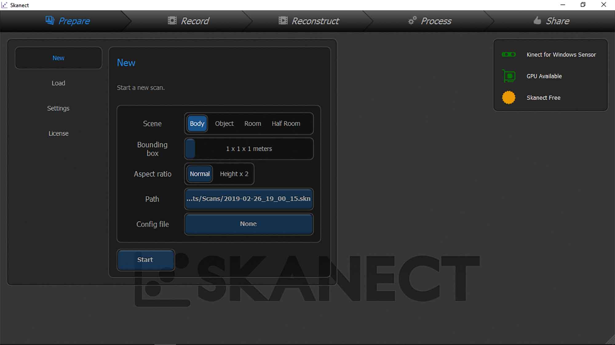
Skanet softwere
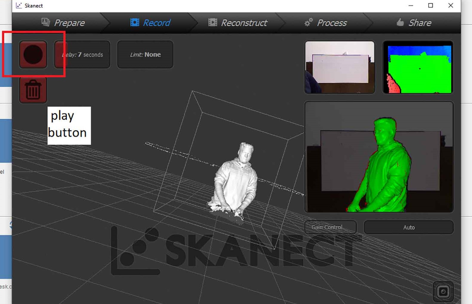
Scanning with Skanet Softwere
Scanning with Skanet software, by using the Kinect we have to Rotate the object. I chose Body because I was going to scan my friend's body.
Rotating object
In this image, the Green area shows the area which is scanned, and red dots show parts which are remained to cover.
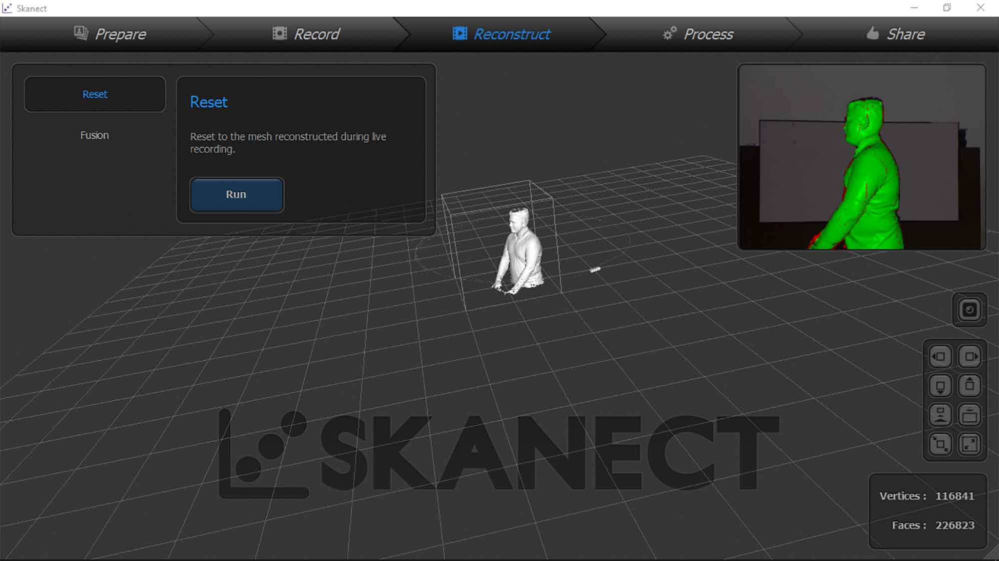
Reconstruct
Reconstruct will help you to regenerate the surface by scanning recorded videos.
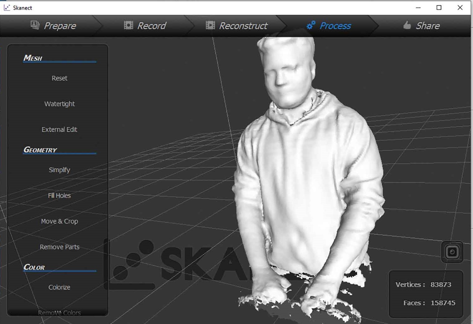
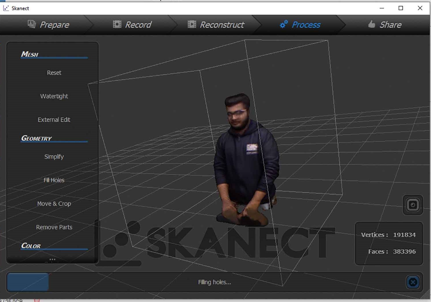
Post-processing
Post-processing : Clearing the holes, Colorizing the model, and making model watertight.
Final
our watchman uncle ready to get scanned
New Skanect Model by dhruvpatel2991998 on Sketchfab
About original files
Unfortunately, we had some misunderstanding about the Skynet software that we cant download original files from the software, so we thought we cant get original files from select, but it was Half-truth, we could just export it in STL format after necessary editing if needed. So I have to Rescan Maharshi and exported Stl file. one can download files from the slide bar.
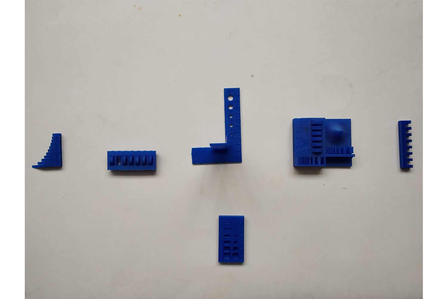
Group work
The assignment was to test the design rules for our 3d Printer. The printer that the lab owns is an Ultimaker 2+. There are different kinds of tests that are done to check the ability of the printer before it fails. Each one of us took up different tests and I was assigned the overhang test. I test angles to 20 degrees to 70 degrees on the flash forge and found out it is really good in maters of overhang, you can see above in my design I went up to the 85 90 degrees without any supports and I can go straight to 0 or 180 degrees for average 15 cm distance. These are my observations. below are some images of overhang and another test described on the website.
click here to visit group website.
Other tests
Conclusion
This week was very exciting and one of my favorite weeks, I always wanted to work with 3d scanning was a kind of bonus. thought I took some big steps in excitement I wanted to make something that is not so common is making or some patterns that can check how far 3d printer goes, I start by Voronoi designs and then realized it was too much (For Ultimaker especially) , I learn to 3d print in parts or have some test print first, it helps to Decide settings for 3d printing and by that, we can have a different experience of parameters. 3d scanning was also very cool, it is cutting of technology we can also make something by only scanning it is some futuristic idea.