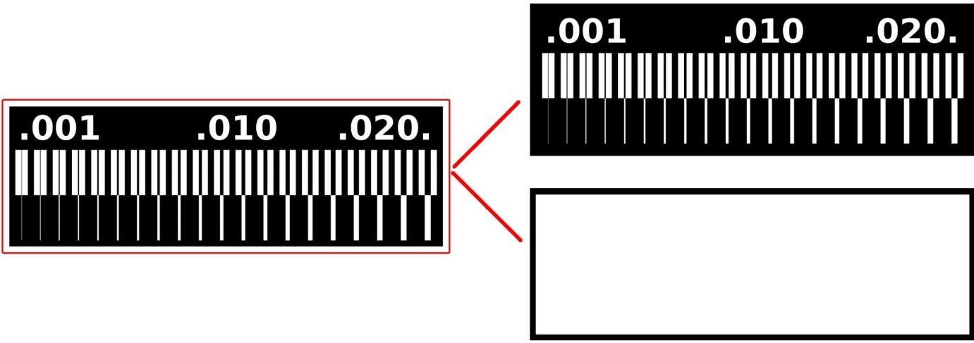
Electronics production

I. Design rules of our PCB production process

A. Image editing

  1. Download the provided black and white image
  2. Open the image in an image editor (Gimp, or Photoshop)
  3. Clean the image: Zoom and inspect the image, erase all discontinuities
  4. Extract two images from the cleaned image:
  5. Check the image size in the image editor (in image menu for Photoshop): Both images should have the same size and be in scale with the PCB.
  6. Check resolution: It should be high enough (>1000 pdi)
  7. Save (or export) both images as PNG files in order not to lose resolution

photo

B. G-code generation

  1. Import PNG image in Fab modules (other formats may be imported for other applications)
  2. Select the machine type: Our machine is a Roland mill (.rml)
  3. Select process:
  4. Check again image size and resolution (it should be as set in image editing)
  5. Invert colour if needed (if it hasn't been done in image editing)
  6. Select the machine model: Our machine is MDX-40 model
  7. 7Select speed (specifies milling/cutting speed):
  8. Set starting position to zero: X0, Y0, Z0=0 (so the milling/cutting will start at 0,0,0)
  9. Select the cut depth:
  10. Select the diameter tool:
  11. Select number of offsets (specifies the number traces per line):
  12. Select the offset overlap (specifies the percentage of crossing between offset traces): 50-70% should be good
  13. Leave other parameters as default and click the calculate button
  14. Once the calculation is completed make a visual check to ensure that the number of offset is as set and that there are no unexpected lines (if there are it means that the image was not properly cleaned: go back to step 3 in image editing)
  15. If all looks good save the g-code file (.rml in our case)

photo
photo

C. Milling machine operations

  1. Fix the copper board on the milling table with double side duct tape
  2. Select the milling tool (0.4mm for milling; 1mm for cutting); inspect the tip to check for default or damage.
  3. Install the milling tool on the machine (care must be taken not to damage the tool to avoid breaking it or loosing milling precision)
  4. Open the operating software of the machine and add the g-code file for traces to the file list.
  5. Open PRINT SETUP (in the file menu), and select the machine model (Roland MDX-40)
  6. Open properties (in print setup window) to view settings in three tabs
  7. In SIZE TAB: The MDX-40 has a bed of 305x305mm
  8. In TOOL TAB: Set RPM to 4,500 for milling 10,000 for cutting, then set properties according to the specifications entered in Fab modules. The g-code parameters will give command, but machine settings should be set in conformity with g-code to avoid conflicting settings and for clarity (In particular set the Z Down Position is 0 for milling and -1.7 for cutting).
  9. In the OPTIONS ATB, open the OPERATIONAL PANEL to position the milling head:
  10. Return to the main menu (the file list menu); select the rml file to be milled and click the output button to launch operation.
  11. Observe operation and eventually pause operation to inspect the milling precision. In the MDX-40: press view (wait until the head is in stand by position); open the cover, clean up with vacuum, and inspect. If it looks good close and press view to resume. If it looks bad check again the quality of the milling tool and fixation of the board: Make sure the duct tape is placed symmetrically
  12. Try again. If there is no improvement, go back to step 1 in g-code generation to check and adjust settings.
  13. When the milling of the traces is done and looks good, inspect the PCB with a multimeter.
  14. Go back to step 2 and repeat operations for cutting the outline.
photo
photo
photo

D. Result:

photo

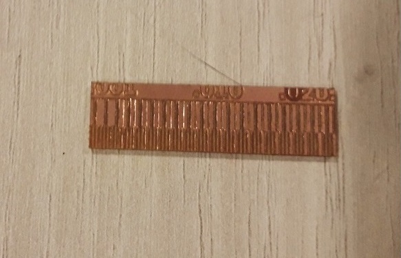
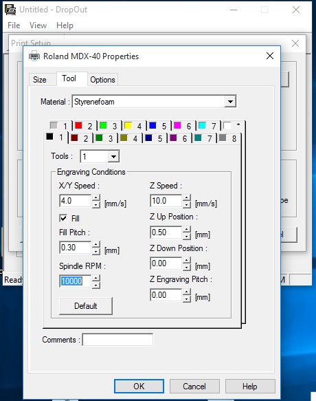
The fist test wasn't good, the cuts were not clean because the cut was too deep and and we were using the 0.15mm thread. the z-axis leveling a bit. We should be using a 0.4mm tool (1/64inch) rather than 0.15mm.

photo

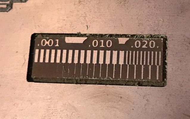
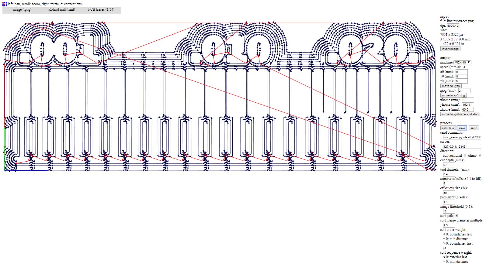
Several tests failed with the 0.15mm. We then used a 0.4mm trhead and found the right calibration z-axis, lowering the milling head till it touches the board (beeping the multemerer) and then raising it a notch (2 pushes up). RPM was at 4500. With these settings the result was clean


II. ISP board

A. Making an ISP board

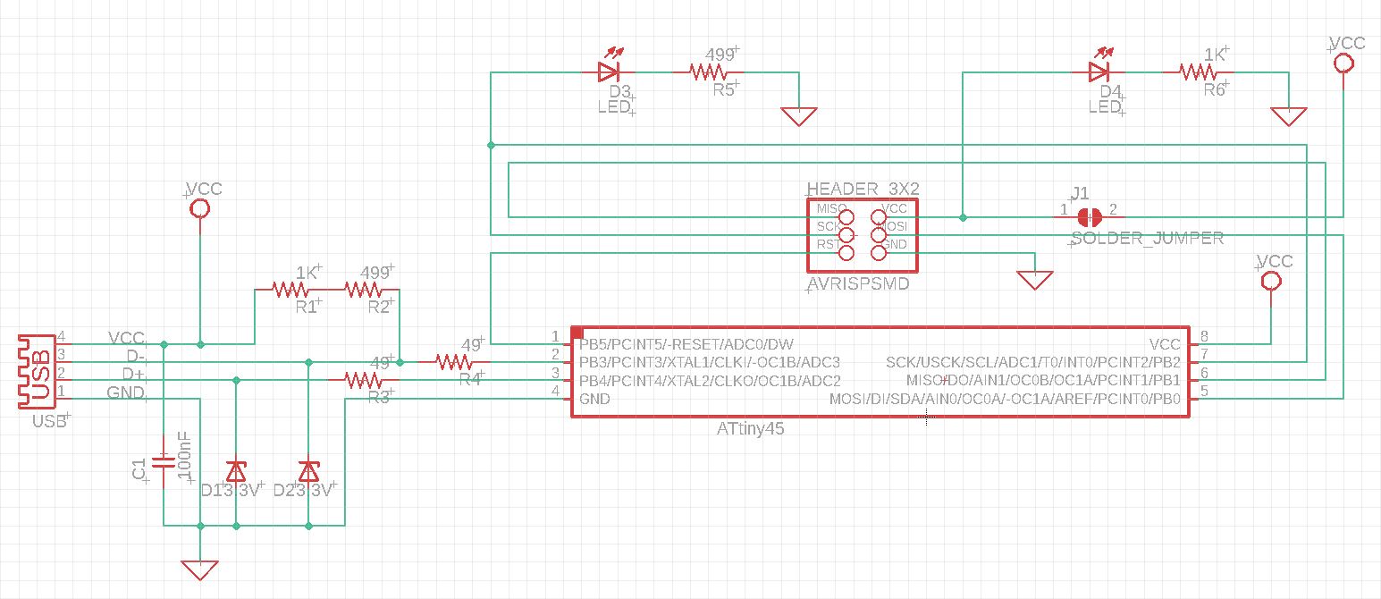
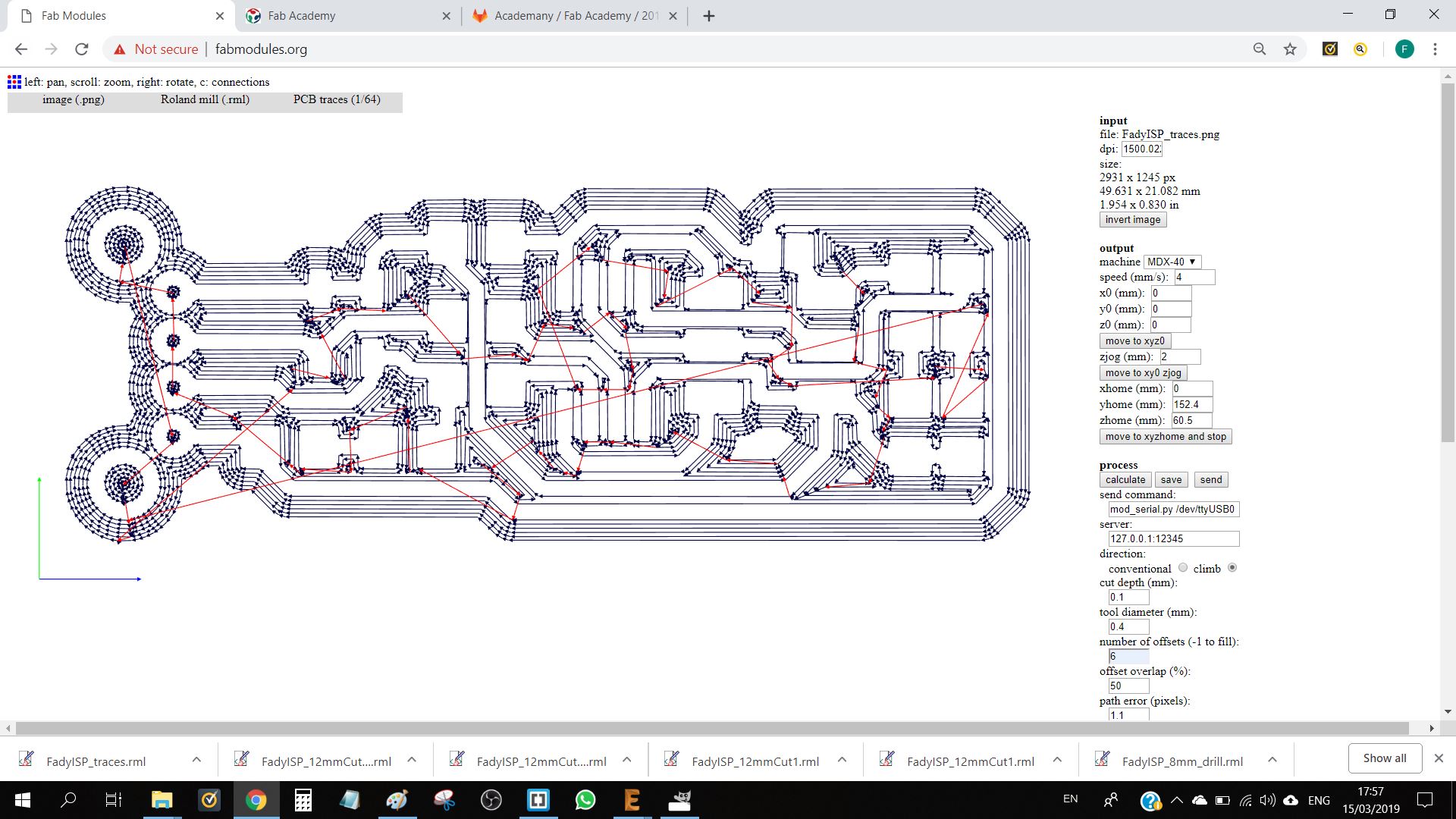
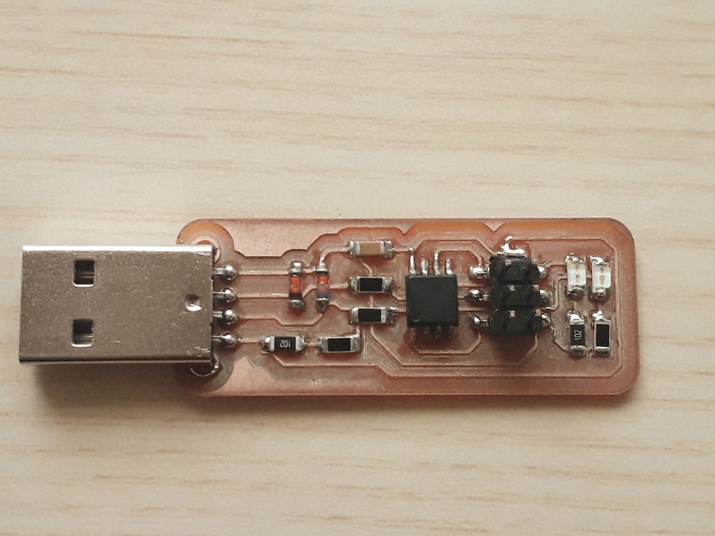
The ISP (In-System Programming) board is a programmer that will enable us to program microcontrollers already assembled in circuit rather than programming them prior to assembly. Our SIP board uses an Attiny85 AVR microcontroller manufactured by Atmel. I drew the diagram and the pcb on eagle. The design is an edited version of Brian's


circuit
circuit

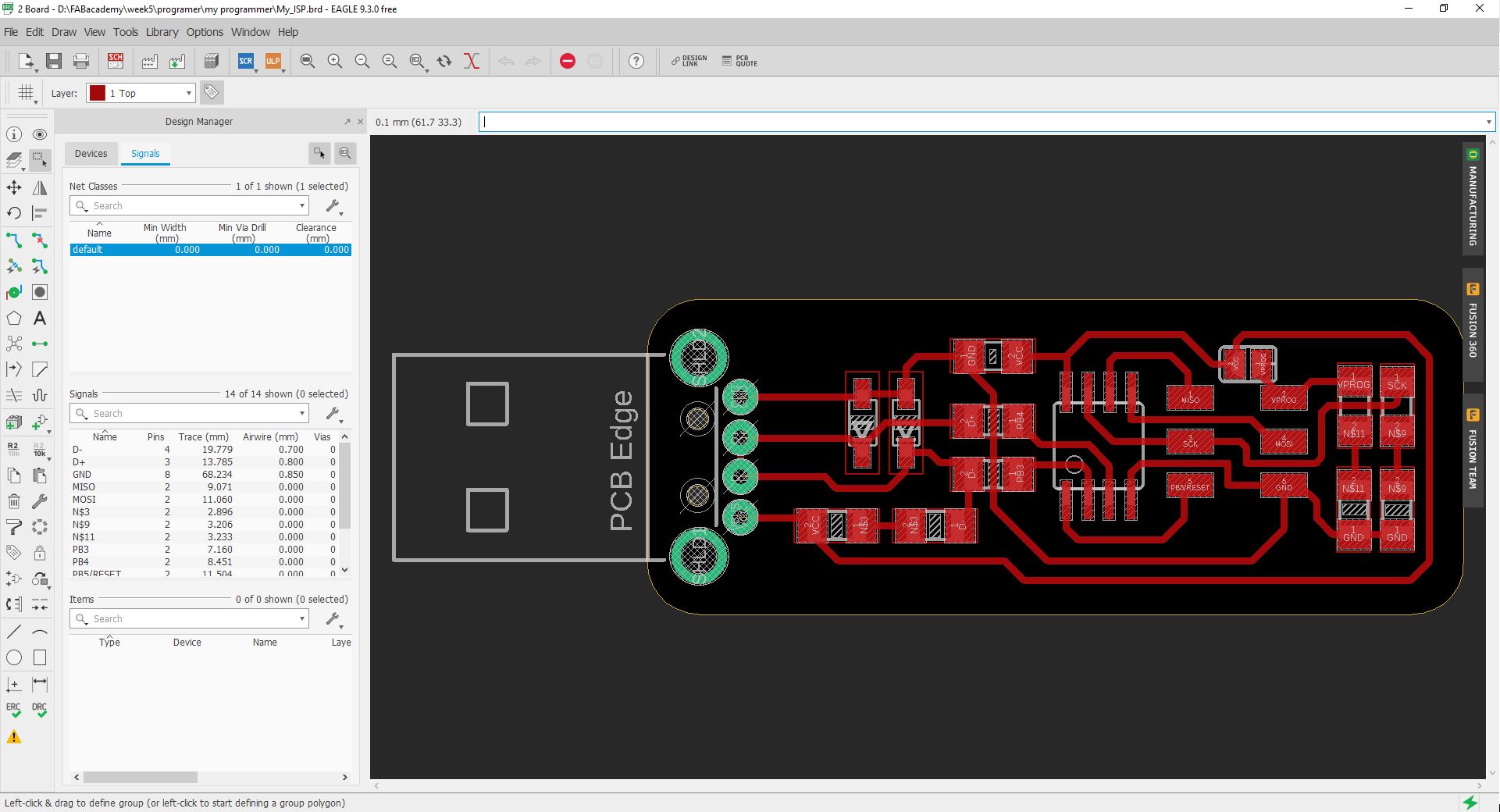
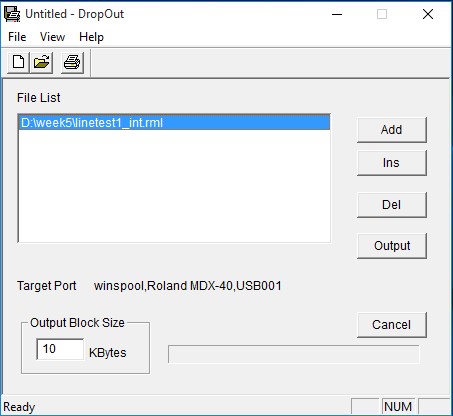
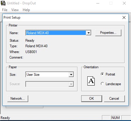
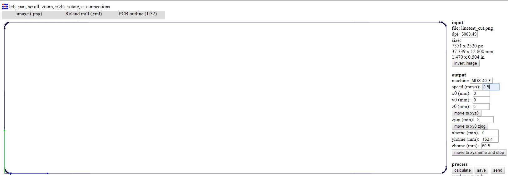
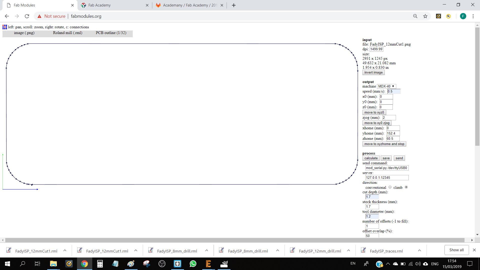
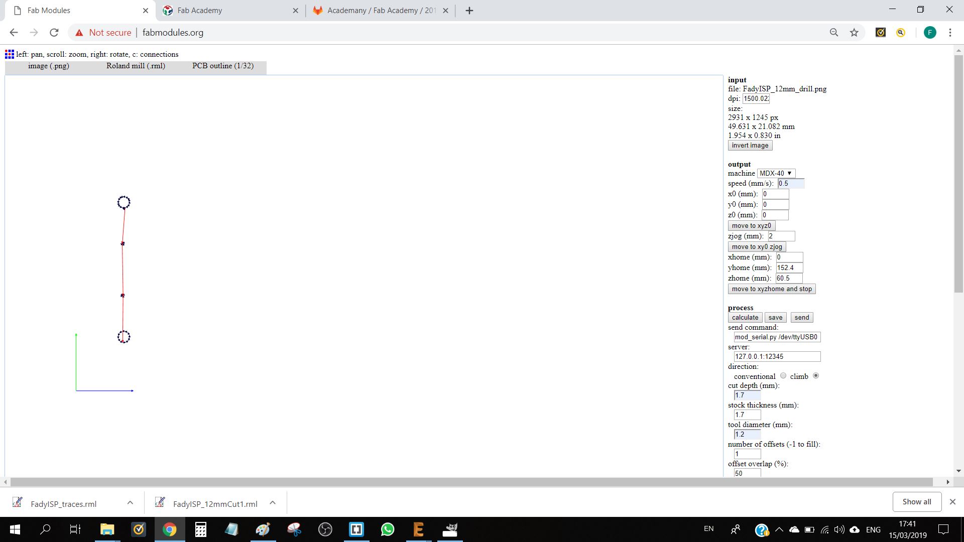
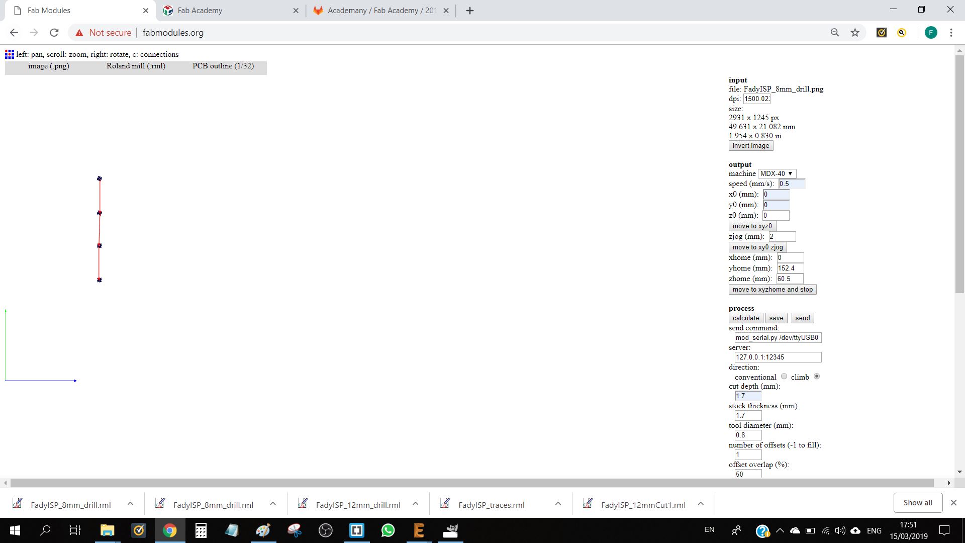
The milling and cutting process is the same as the one described above for the test board, with the addition of two gcodes for drilling with an 0.8mm and a 1.2mm thread.

circuit
circuit
circuit
circuit
circuit circuit circuit circuit

The component used for this board are:

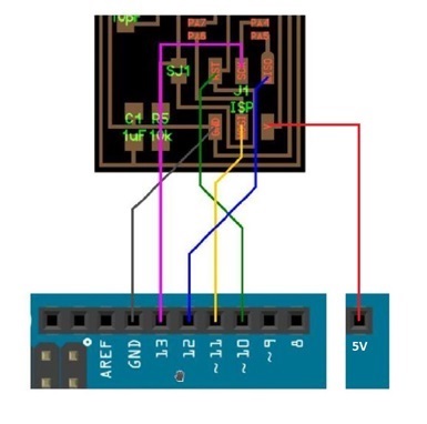
After soldering all the components, solder the jumper J1 before programming the ISP.


photo

B. Programming The ISP

photo

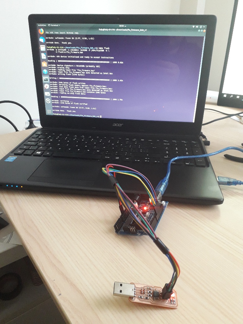
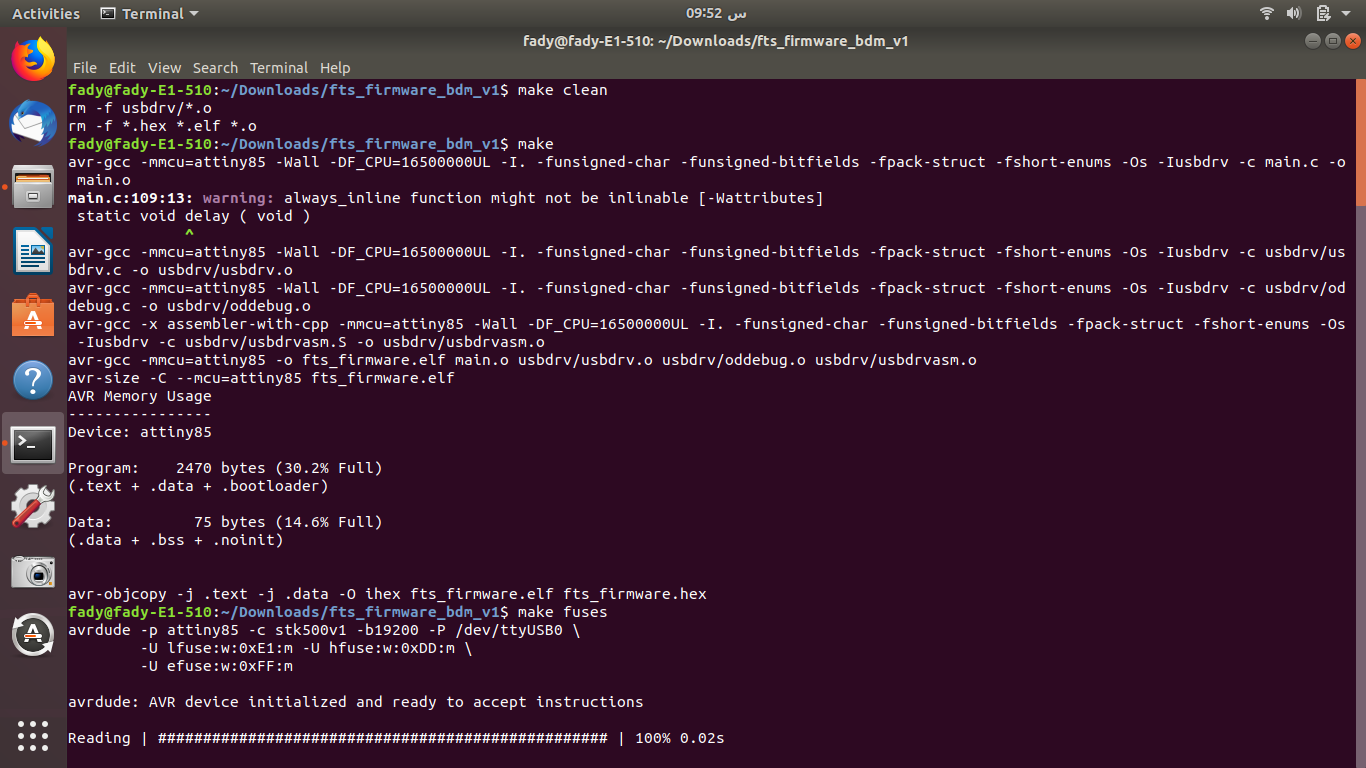
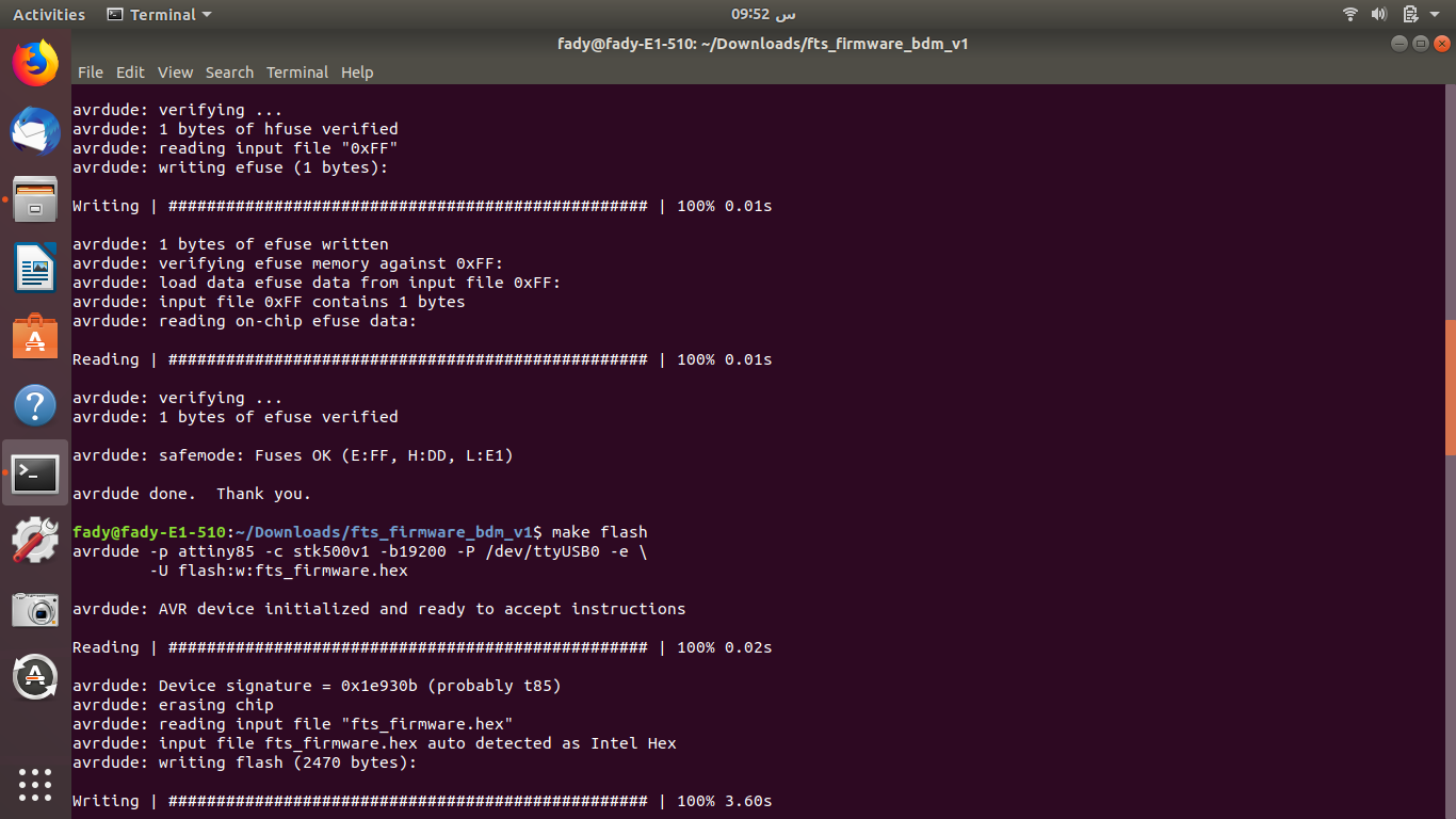
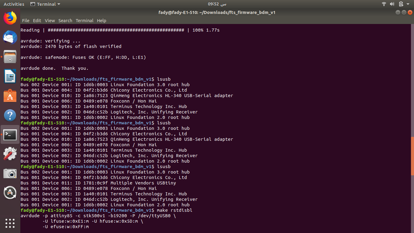
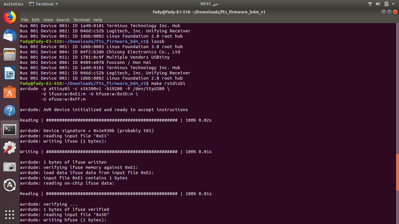
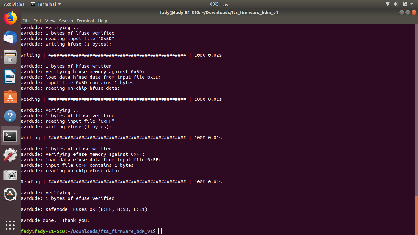
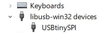
The steps for programming the ISP are:

  1. Download and open the Arduino software (IDE)
  2. In TOOLS, select the port and the Arduino model (Ardiuno UNO)
  3. Connect the Arduino programmer to the PC
  4. In FILE>EXAMPLES open ArduinoISP and upload it
  5. Connect the Arduino to the ISP as shown below
  6. Edit the makefile with your IC type, programmer code, and port name.In my case:
    • MCU = attiny 85
    • PROGRAMMER = stk500v1
    • port = /dev/ttyUSB0
  7. Replace the make file with a new make file (modified makefile)
  8. Open the command prompt in Linux and go to the code directory
  9. Enter the commands to generate a make file:
    • make clean
    • make
  10. Open the Make file with Brackets and replace MDU=attiny45 by MDU=attiny85. Save file
  11. Then Enter the following commands to load the programme on the ISP:
    • make fuses
    • make flash
  12. To test the ISP plug it and type lsusb. You should read Multiple Vendors USBtiny
  13. In windows, In Control Pannel> Devise Manager. You should see:
  14. photo
  15. If the ISP is recognized, the last step is to make its programing irreversible and to set the RESET Pin as GPIO. For that end the command is:
  16. make rstdisbl

photo photo photo photo photo photo