View A
View B
View C
View D
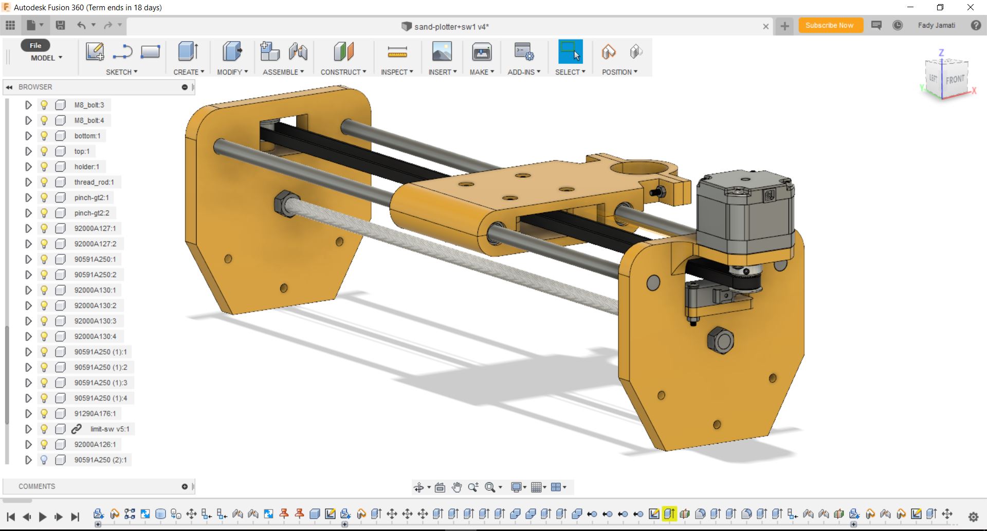
Our group project for mechanical design week consist of a sand plotter. The function of this machine is to draw figures with sand on a street or open area. The plotter includes a body with wheels, a linear rail module, and a container with a valve. The machine can move forward with the wheel mechanism, and move the sand container sideways on the linear rail mechanism. My part was to design the linear rail module.
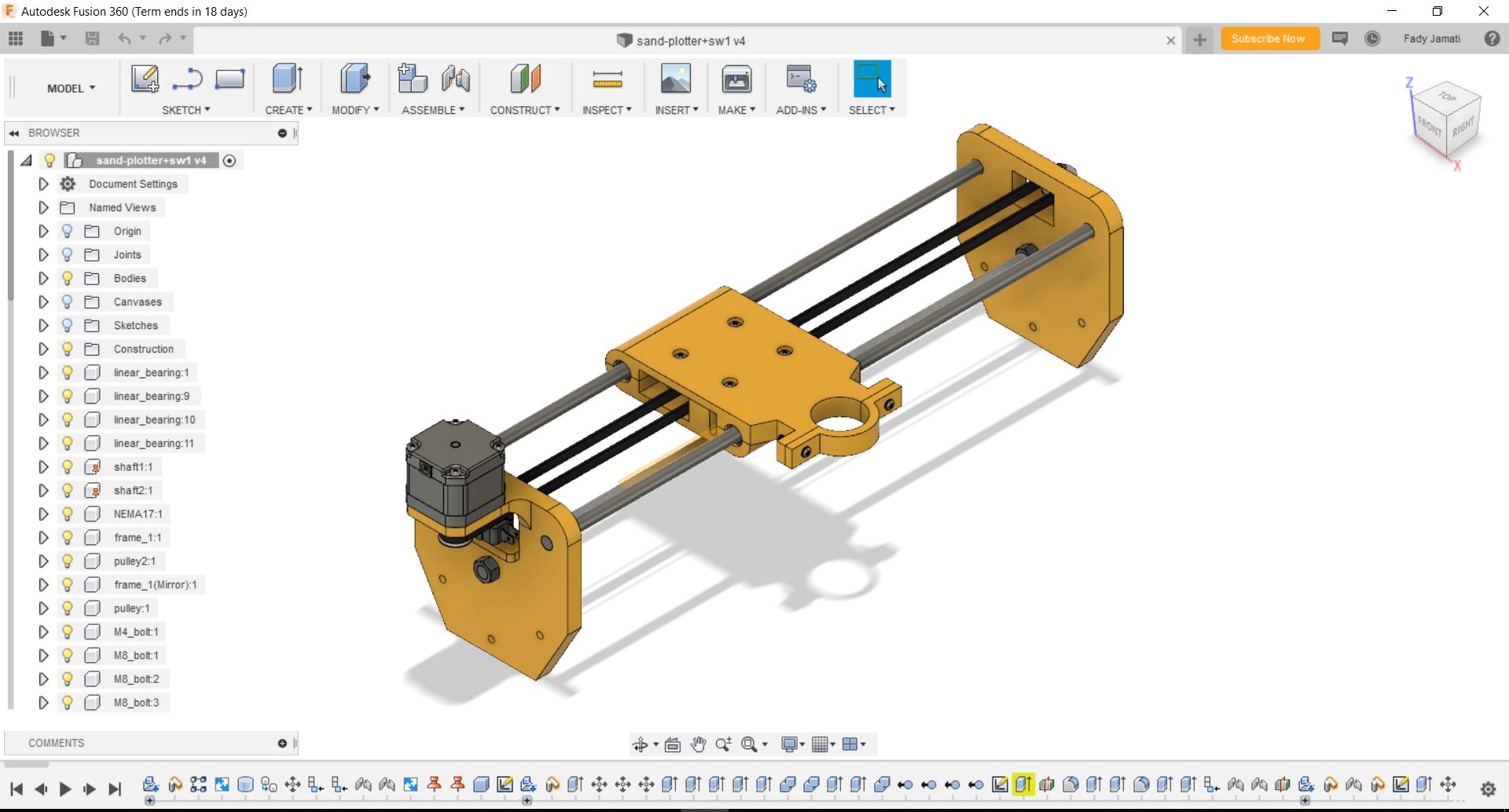
The first step was to design the module on fusion, using Mc-Master componenets
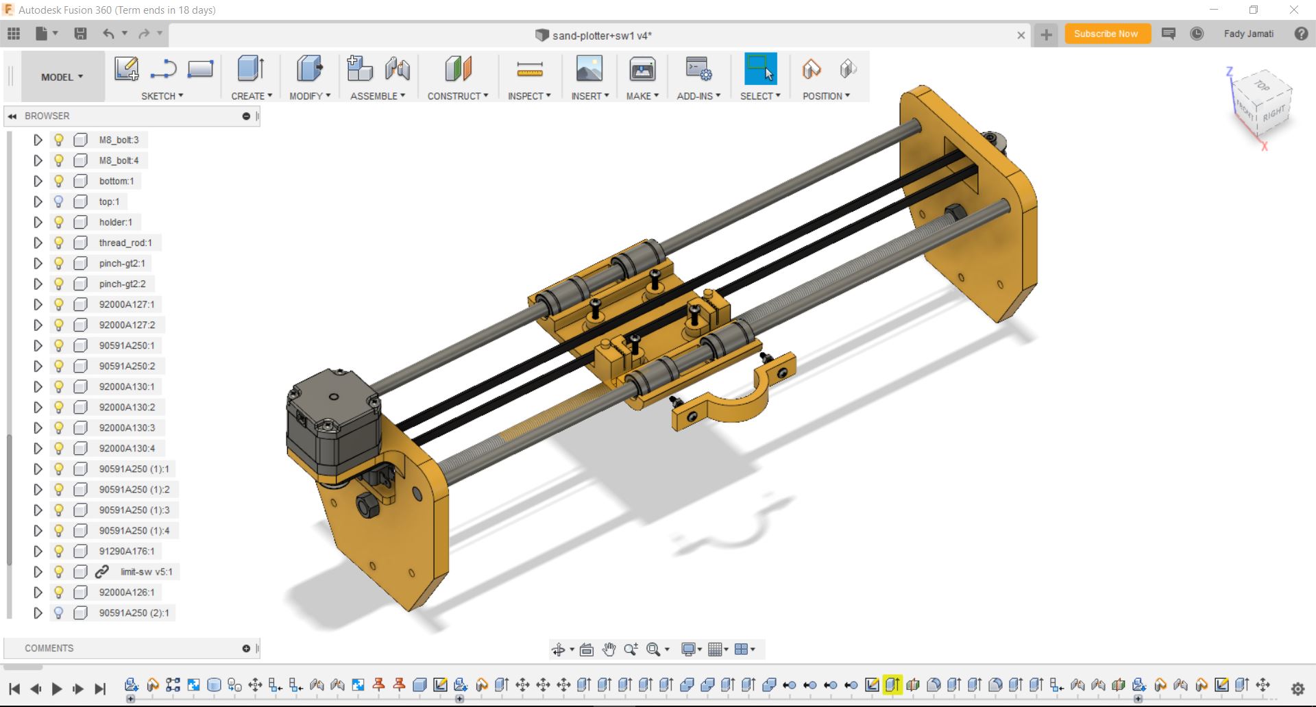
The design includes two linear rail which are 40cm stainless steel rods, four linear bearings, a stepper motor, a limit switch, and a gt2 6mm driving belt. The rails are held by two side frames and a threaded rod. The linear bearings are fitted to a moving plate which consists of three parts, a top part wich include grooves for fixing the driving belt, and a top part with is attached by screws and bolts to a holder meant to fix the container. The top and bottom part are also attached by screws and bolts.
Note: The design shows the driving belt as closed, but in the assembly the driving belt will be cut and fixed in the grooves in the bottom plate.
View A
View B
View C
View D
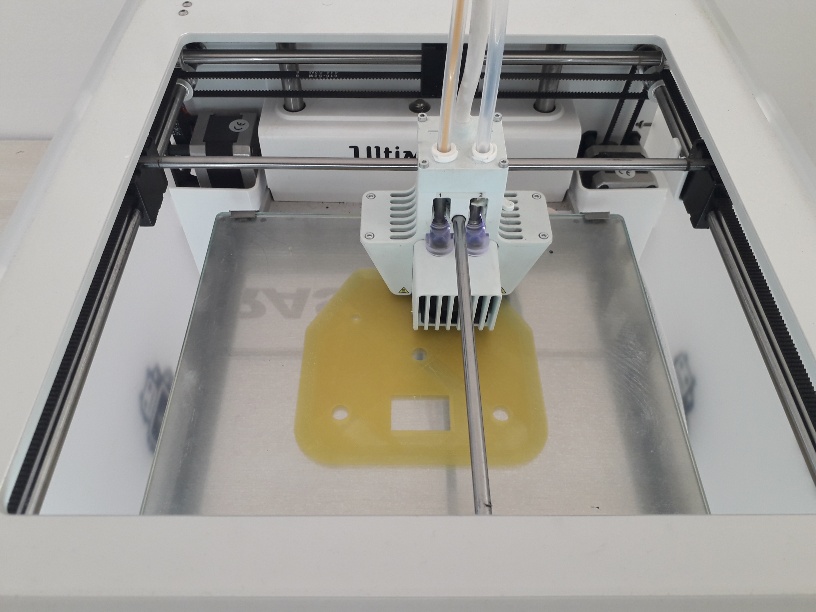
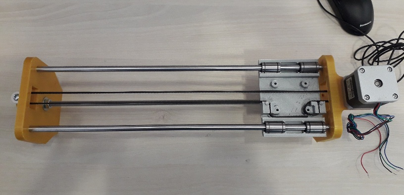
The next step was to 3D print the side frames and the moving plate parts. I used the Ultimaker 3D printer
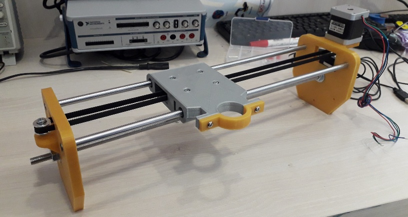
The next step was to assemble the module. The linear rail module is meant to be assembled with the main body, but first I assembled the module separately. The parts fit well which is the most important. The driving belt fist tightly in the grooves. I little hiccup was that on the grooves was not mirrored with the other, so the driving belt is fixed in different ways on the two grooves (picture C).
View A
View B
View C
View D
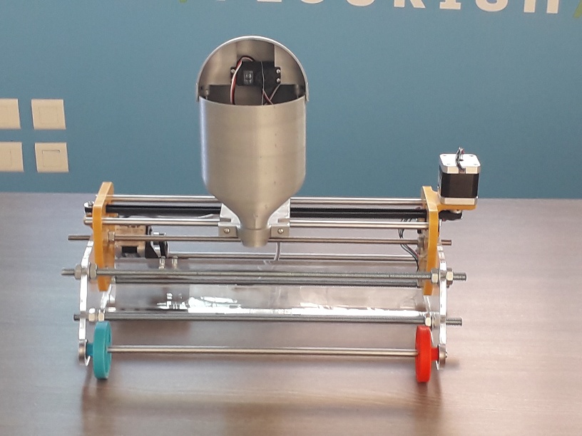
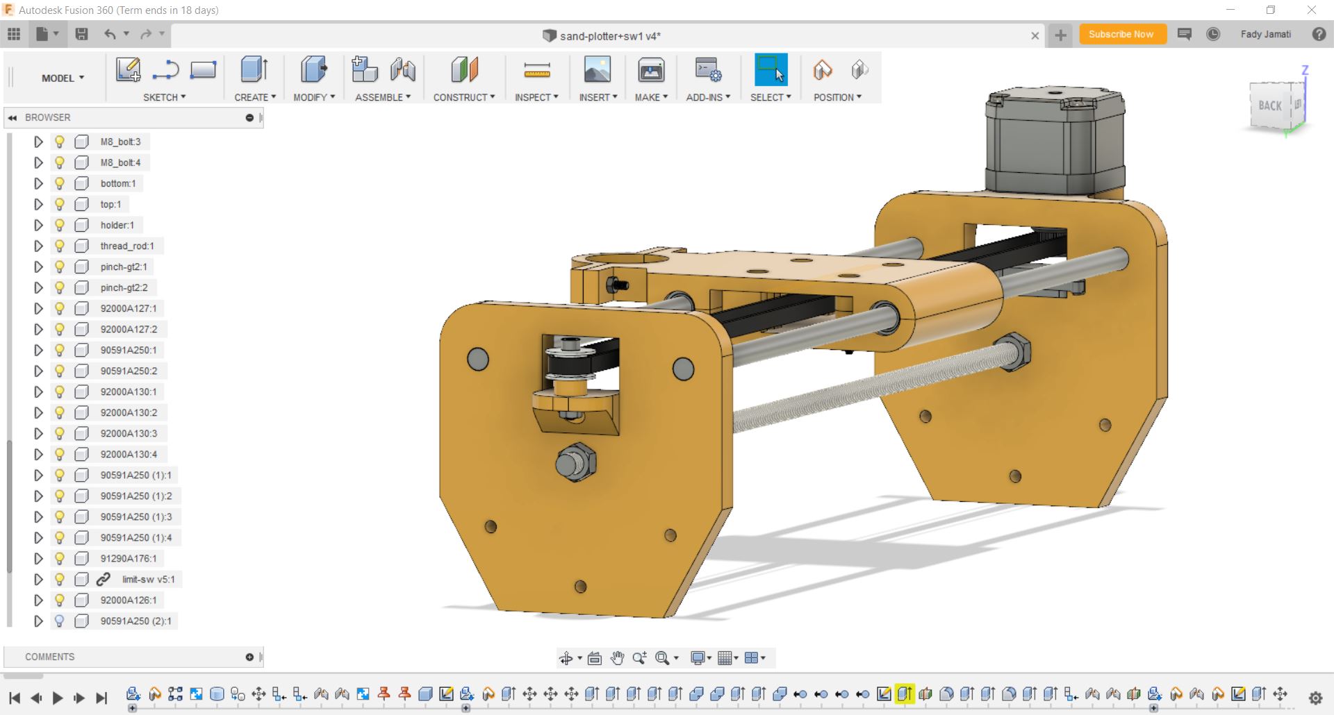
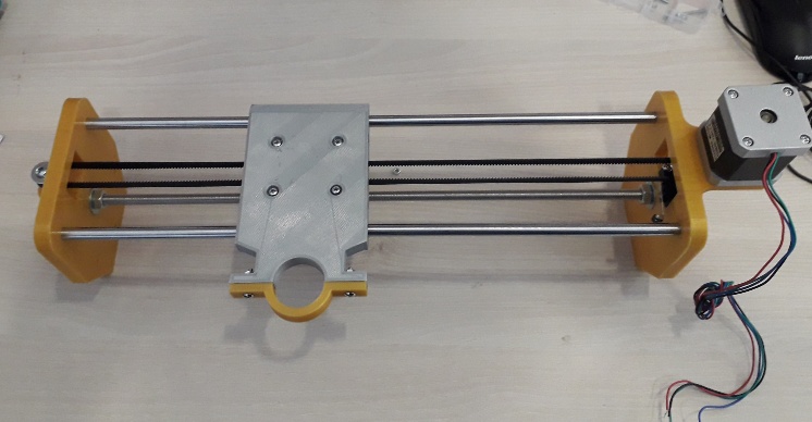
The final assembly of the CAD design looks like this
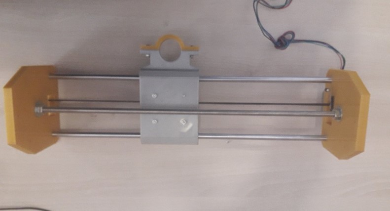
he assembly of the real parts is nearly finished. Still missing a couple of wheels as well as the tires.