I. Characterize your laser-cutter
Machine:
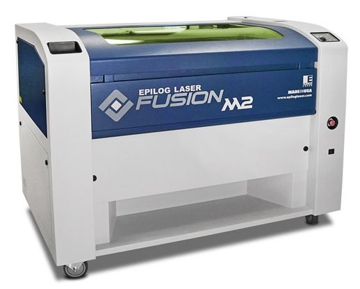
Laser cutter - Epilog Fusion M2
Materials available:
- 3mm MDF -which happened to be of 3.17 mm after measuring it accurately with the caliper
- 5.5 mm MDF
For cutting, the power of the laser cutter should always be 100; It varies for engraving.We calculated the kerf of our laser cutter via two types of tests.
First test:
- Objective: Select the best cutting setting in terms of speed, power, and frequency. In our case, for wood, power and frequency are known. Cutting speed needs to be determined
- Method: Cut multiple lines with different speed settings around the reference speed provided by the manufacturer's specifications. Observe by eye at which speed the material is fully cut. The first fully cut line should be the thinner cut, thus the smaller kerf.
Second test:
- Objective: Measure the kerf for the setting previously selected.
- Method: Cut one or multiple segments with the same setting. Measure the length of the outer frame, measure the length of the adjacent cut segments, divide the difference by the number of cuts. The result is an estimation of the kerf. We made two tests with different layouts to get an average.
1. How to perform the tests:
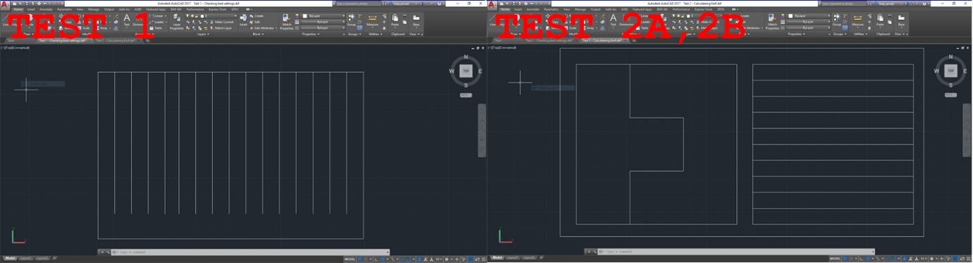
A. Drawing a test layout.
- Draw a layout on a vector type CAD (we used AutoCAD). Make sure there is no line superposition to avoid cutting the same line twice. The lines that should be cut in a single cut with same parameter should be joined into one line. (Click 'Ctrl + A' then 'Join')
- Save as DXF 2007.
- Import DXF file in Corel Draw. Make sure all the lines are hairlines (hairline will be cut; other lines will be engraved). Place the drawing in top left corner.
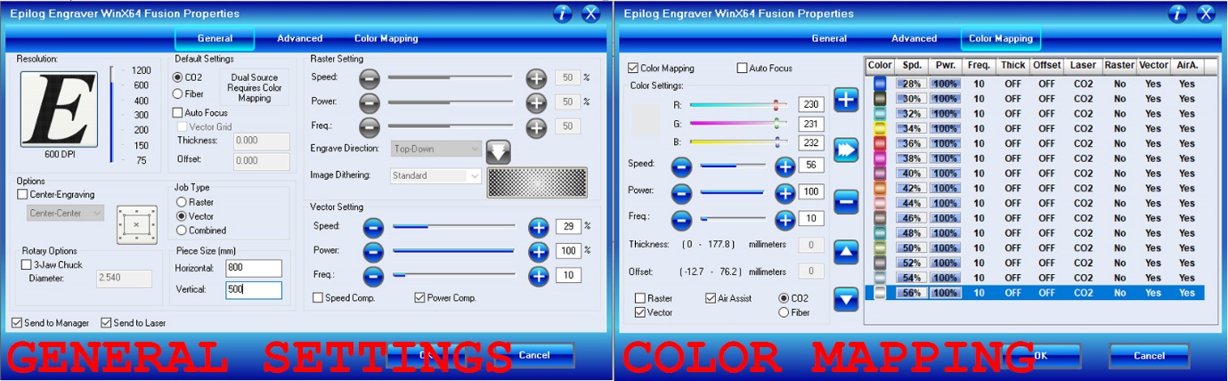
- Open the laser cutter properties window (Ctrl + P for printing the job). In the general tab select vector job type, select top left corner for positioning, enter machine bed dimensions (800x500 mm for our machine)
B. Colour mapping (for test 1 only):
- Colour mapping helps in feeding different settings for each different line, so that the laser cutter understands that it should not cut all the lines in the same way or speed
- In Corel Draw, colour each line with a different colour and note the RGB of each colour.
- In the laser cuter properties window, open the colour mapping tab, copy the RGB previously noted and assign cutting parameters for each colour, specifying speed, power, and frequency (in %).
- For wood, the power will remain at 100%, and the frequency at 10% according to the manufacturer's specifications. So in this case only speed will vary.
- According to manufacturer's specification, the reference speed value for wood is 40%. So the speed setting will have to range around this value.
- Select vector and deselect raster to cut and not engrave (it shouldn’t make a difference if all the lines are hairlines).
C. Operating the laser cutter.
- Turn on the machine, then load the file to the laser cutter by clicking print. From there, the work is on the laser cutter interface.
- Position the wood board on the laser cutter metal bed. Then place the gage tool to calibrate the focal point of the laser on the right z value. When the gage touches the board, zero z. Then move the laser cutter head to the starting position and zero xy.
- Before starting, make sure that the compressor is turned on, as well as the extractor, to enable air flow to evacuate the fumes and prevent fire risks and toxic fumes inhalations.
- Start cutting, and supervise the machine till the job is completed (the laser cutter should not be left without supervision while operating).
- Once the job is done, wait for fumes to be fully evacuated before removing the board.
2. Test results:
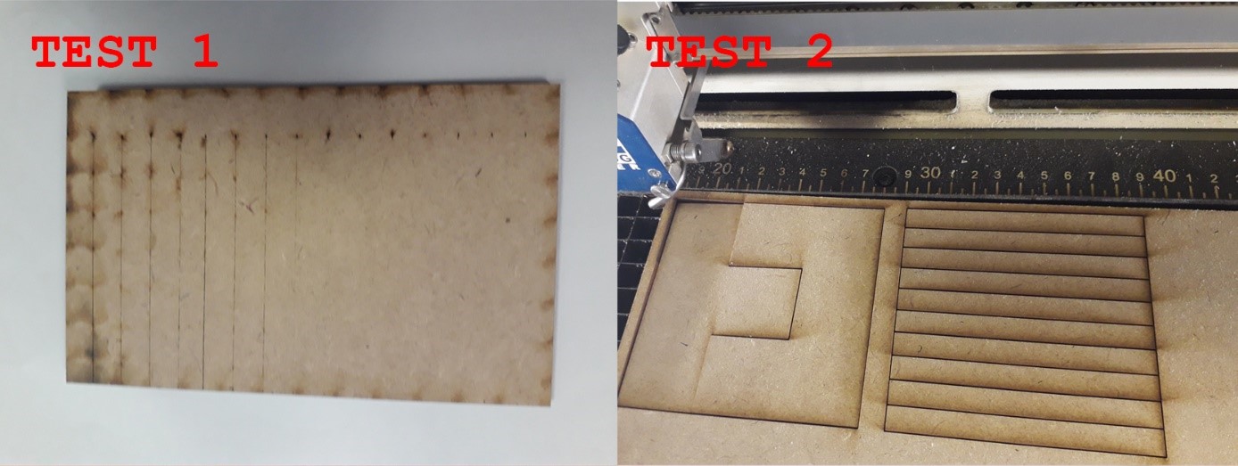
First test: The best cut appears to be between 28 and 30% speed
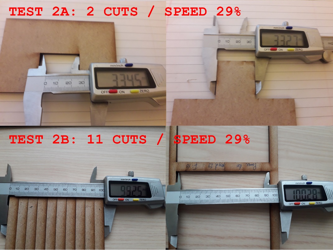
Second test:
Evaluation of the kerf for speed 29%:
- Test 2A:Kerf = (33.45 - 33.27) / 2 = 0.090
- est 2B: Kerf = (100.28 - 99.25) / 11 = 0.094
Evaluation of the kerf for speed 30%:
- Test 2A: Kerf = (33.81 – 33.73) / 2 = 0.04
- Test 2B: Kerf = (100.34 – 99.88) / 11 = 0.042
II. Build a press fit construction kit
1. Parametric design on Fusion 360
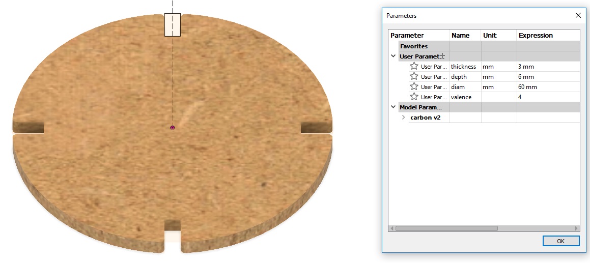
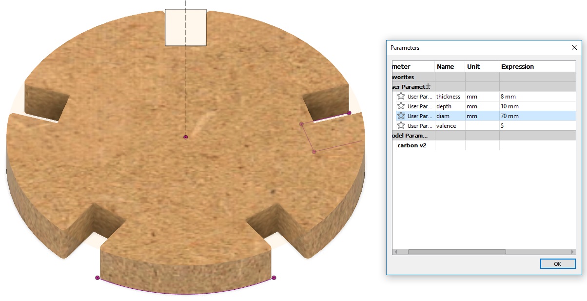
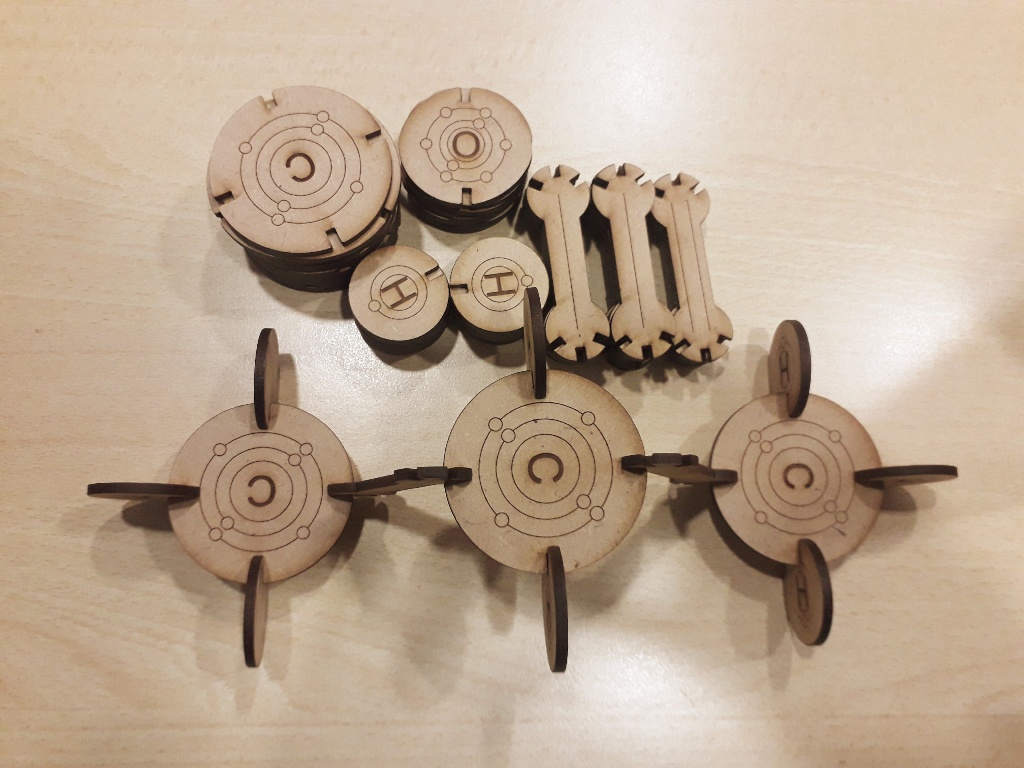
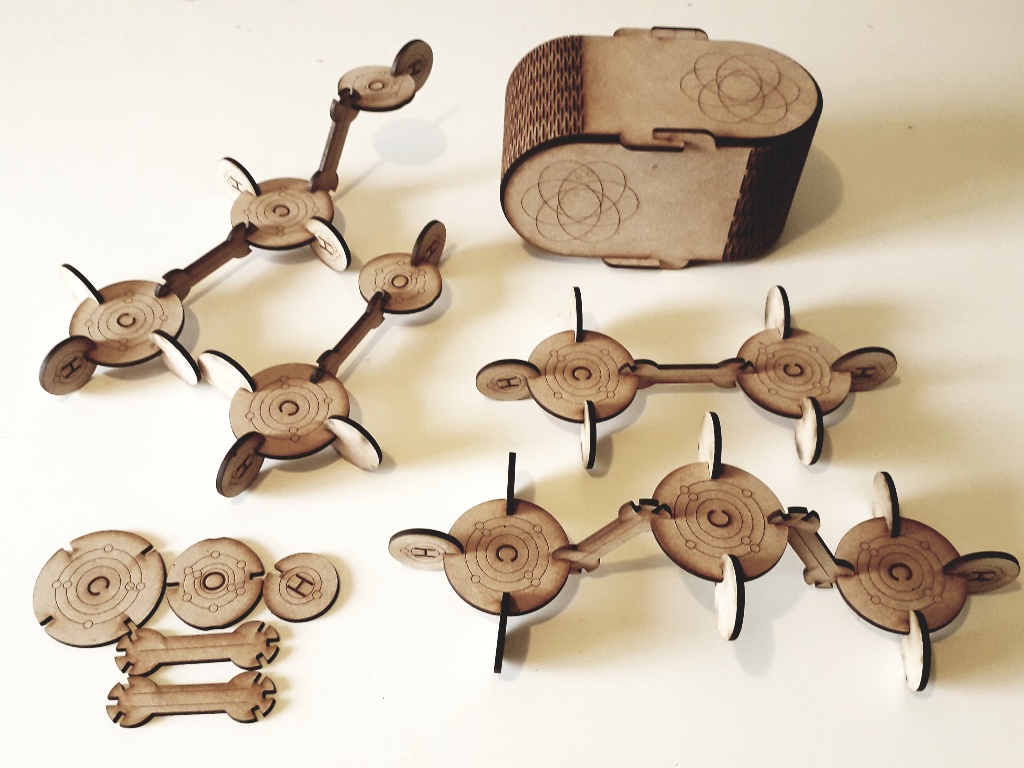
For my press fit kit, I designed a chemistry kit to assemble hydrocarbon and alcohol molecules, so it has an educational purpose. In order to experiment with the flexible design, I build a box for the press fit kit. The press fit kit was designed in a parametric way in fusion. The box was designed in AutoCAD (non parametric). The press fit kit however is fully parametric. I chose to design each element in a separate files and to assemble in separate file, although fusion allows to design different components in the same file. The component in fusion is like a different file within the file, it has its own origin, sketches and bodies. However, I preferred to design in different components in different files like it's done in other CADs (like Inventor) because I wanted to be able to build different assemblies in different files without overloading a single file. The downside when assembled that way is that when you change the parameter in the component file, you have to update the assembly file (The component and assembly files are the same in fusion, you just have to drag one file into the other). The other downside is that you have to change the parameters in each component file before updating the assembly file. This can be changed by breaking the link between files. The press fit kit is to be cut on a laser cutter, so the output file must be a 2D DXF file. There is two ways to produce this output DXF file in fusion: Start by sketching the file in 2D, then transform it in 3D (with an extrude for example), then save the sketch as DXF. Design directly in 3D with 3D tools, then create a sketch on the desired face and save the resulting sketch as a DXF file. I tried the two methods and I found that the second was easier to design the atom parts, while the first worked better for me to design the bond part. Let's detail the steps of making a simple parametric design for one elements of my kit, like the element representing the carbon atom. The element is a disc with four symmetric slots (like the valence of carbon). The design is done in the model environment in the following steps.
- Create parameters. In the modify tab, select change parameters. Add two user's parameters: “Thickness” and “depth”, for thickness of the board (minus two times the kerf), and the depth of the slot. We could also add the diameter and the valence so can transform this design into the design of other atoms.
- Select cylinder in the create tab, and draw a cylinder. Enter the Thickness parameter for the height and the diameter parameter.
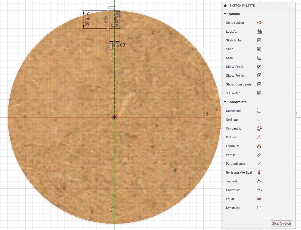
- On the top or bottom face of the cylinder, click and select create sketch.
- Daw a construction line from the centre of the circle to the outside. Make sure one node is constraint to coincide with the centre of the circle. (the constraint command ae displayed on the sketch palette).
- Draw a rectangle and constraint one side to be centred on the construction line (midpoint in the constraints list in the drawing palette). Then select the same side and constrain it to be tangent to the circle. Stop sketch.
- In the create tab select extrude and extrude the rectangle to cut through the cylinder.
- In the create tab select the circular pattern; choose the feature type and select the extrude operation in the timeline at the bottom of the screen. Select the circle as the axis, and enter the valence parameter as the quantity. This will create a circular pattern for the slot.
- In order to make the fitting more practical, make a fillet or a chamfer on each edge.
- Play with the parameters to make sure that the body changes accordingly.
- Select the opposite face of the resulting body, create a new sketch, and stop sketch. Right click on the new sketch and save as DXF. Now we have a DXF sketch of the body outline to be cut with the laser cutter.
- Repeat the previous steps for the other parts of the press fit kit.
Fusion file for the carbon symbol
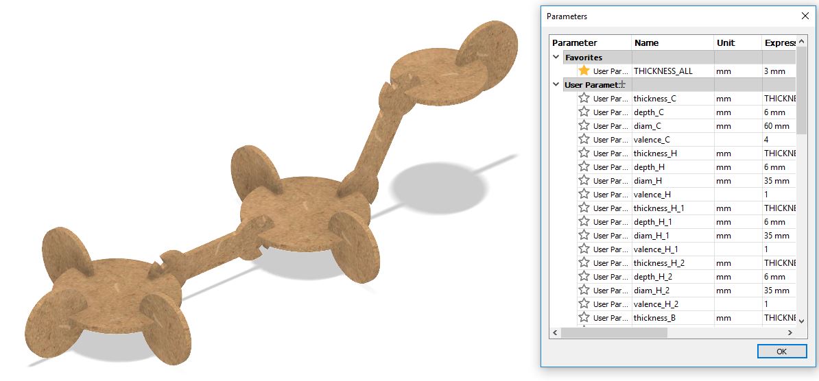
Once every part has been designed, we can assemble them. As we have drawn each part in a different file, we will create a new file for assembly and drag the parts in the assembly file, which become components in the assembly file. If we draw all the parts in the same file we have to create a component from the body parts (right click on the body in the browser and select create component from body). In order to join the components, we have to create joints:
- Select joint in the assemble tab.
- Select rigid type.
- Select a face on the first component.
- Select a face on the second component to be superposed with the first.
- Repeat this steps for every component to build an assembly (a molecule in our kit).
In that case of assembly, the parameters are not accessible in the assembly file but only in the source file. So the in order to change the parameter the you should change the parameter in the component file and save then update the assembly file. If you want to control the parameters in the assembly file, the steps are:
- Right click on each component in the browser of the assembly file and break link
- Go to modify parameter and you will see that the parameters of the source files are now displayed. Parameters are not merged even if they bare the same name.
- Create a new parameter to be common to all.
- Replace the value of the individual parameters by the common parameter.
- Click on the star near the common parameter to place it in the favourites on top.
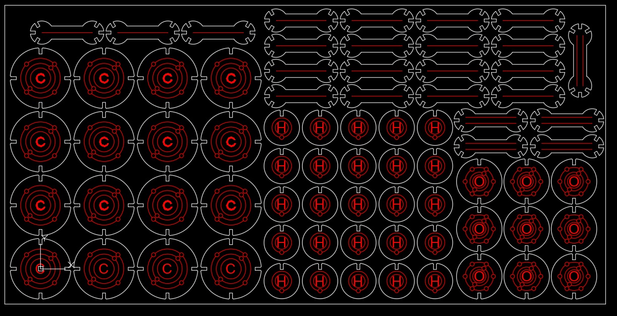
Once the parametric design is done on fusion and the sketches are saved as DXF, the work can be continued on AutoCAD. In Autocad the steps are:
- Open each DXF file
- Select the drawings and place them in the clipboard by cut or copy
- Paste the drawings in a single file
- Additional deco rational drawings or text may be added for engraving
- Create a rectangular pattern depending on the number of parts to be cut
- Arrange the drawings to minimize the cutting space
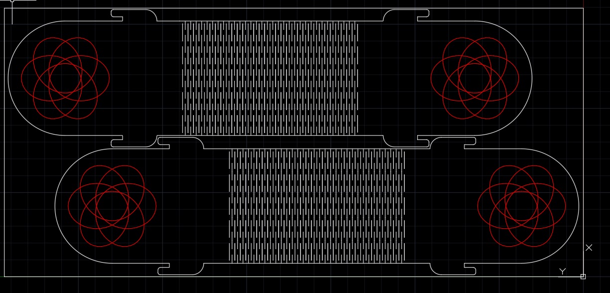
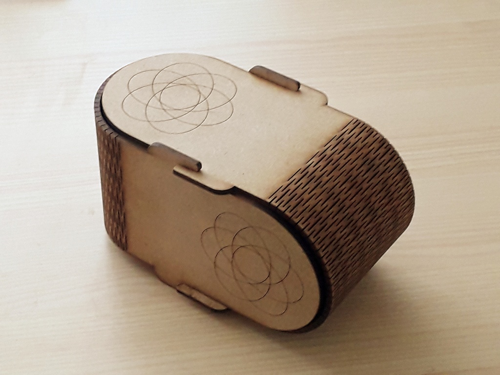
2. Kit container using a flexible pattern
The cut pattern for flexible was downloaded from
"instructables"
The download file was a DXF file. I first importer the DXF file in fusion and tried to build on it, but I run into some problems trying to use the constraint commands, because some commands were not working on the imported file, so I continued the design on AutoCAD building on the imported file. The box is made of two identical pieces including a flexible pattern. The topology of the design is comparable to a tennis ball. The cutting was done according to parameters defined in the common assignment section.
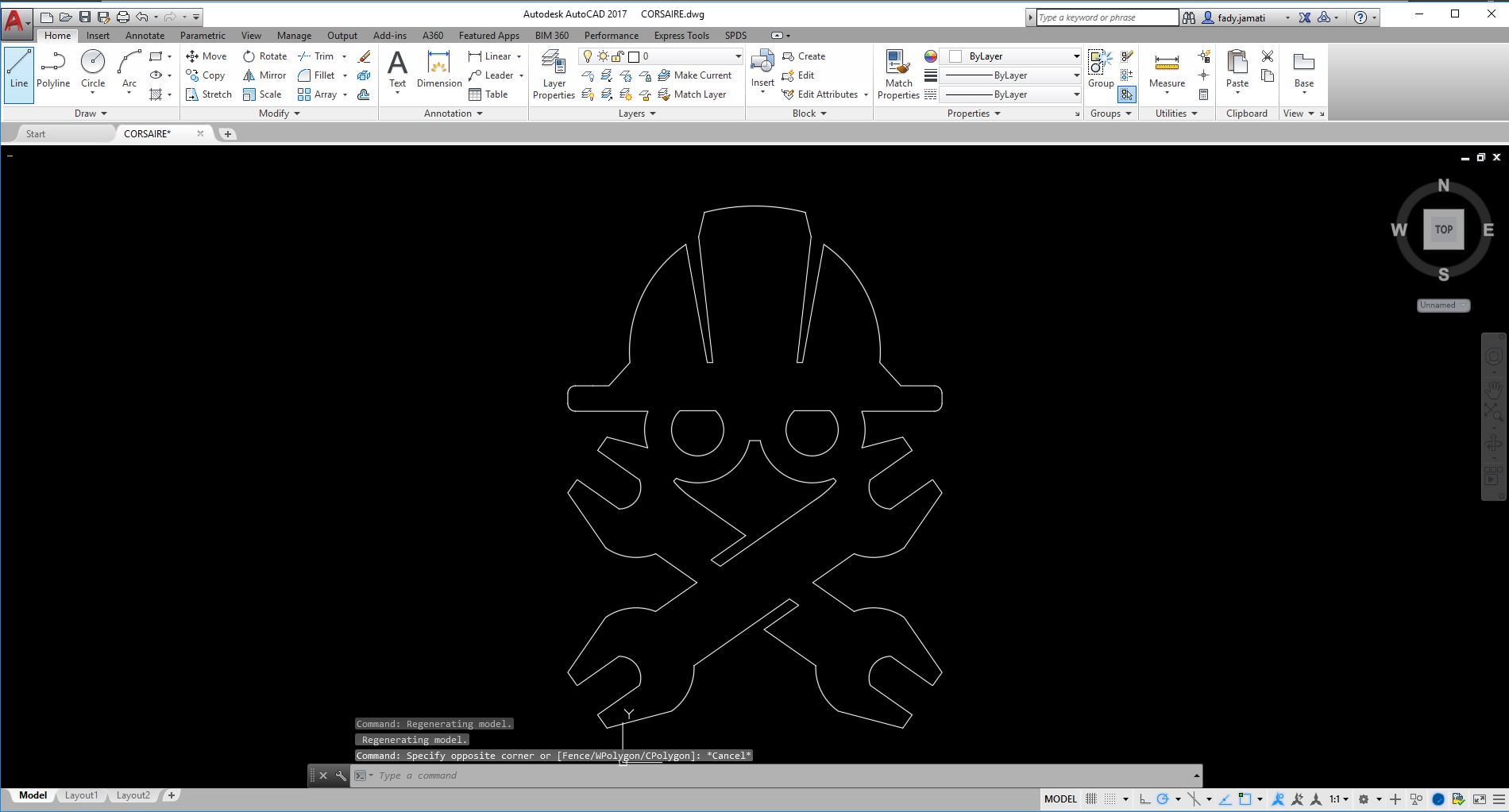
III. Vinyl cutting
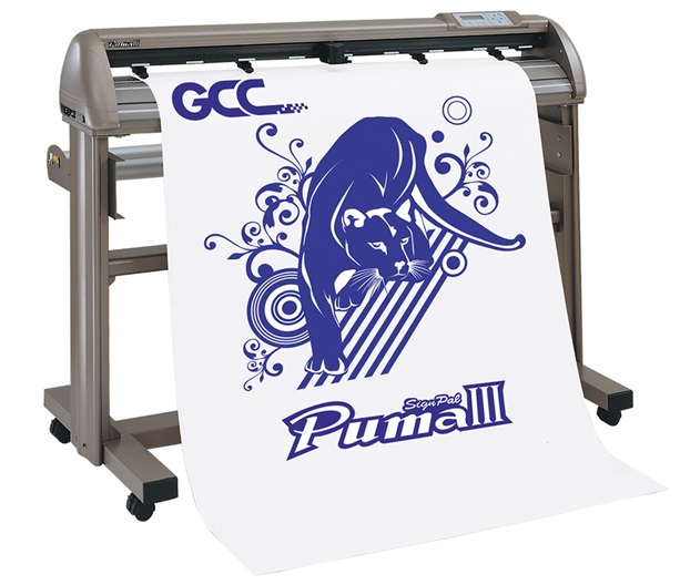
I used the vinyl cutter to do make a sticker for my laptop. The Vinyl Cutter is a GCC Puma. I used Autocad to draw the logo.
The steps to create a vinyl sticker are:
- Create a 2D drawing in a vector CAD and save as DXF
- Make sure the lines are single continuous lines. Join lines when possible.
- Import DXF file in Corel Draw. The sheet width should correspond to the vinyl roll width
- Duplicate the drawing to fill the whole width to maximize the use of vinyl cutter
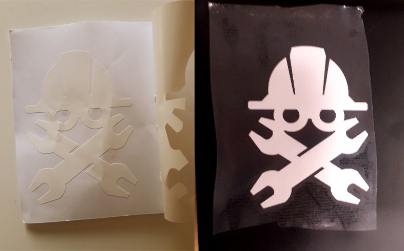
- Load the vinyl roll and turn on the vinyl cutter (to load lift the pressing wheels, load and press the wheel).Start print
- When the print is done cut the printed part with a cutter.
- Cut one sticker and remove the unwanted part.
- Stick a transparent adhesive film on the remaining vinyl shapes
- Remove the back paper support layer
- Stick the transparent sticky film with the vinyl shape on the surface to be decorated
- Slowly and carefully remove the adhesive film (with an oblique movement; not horizontally)