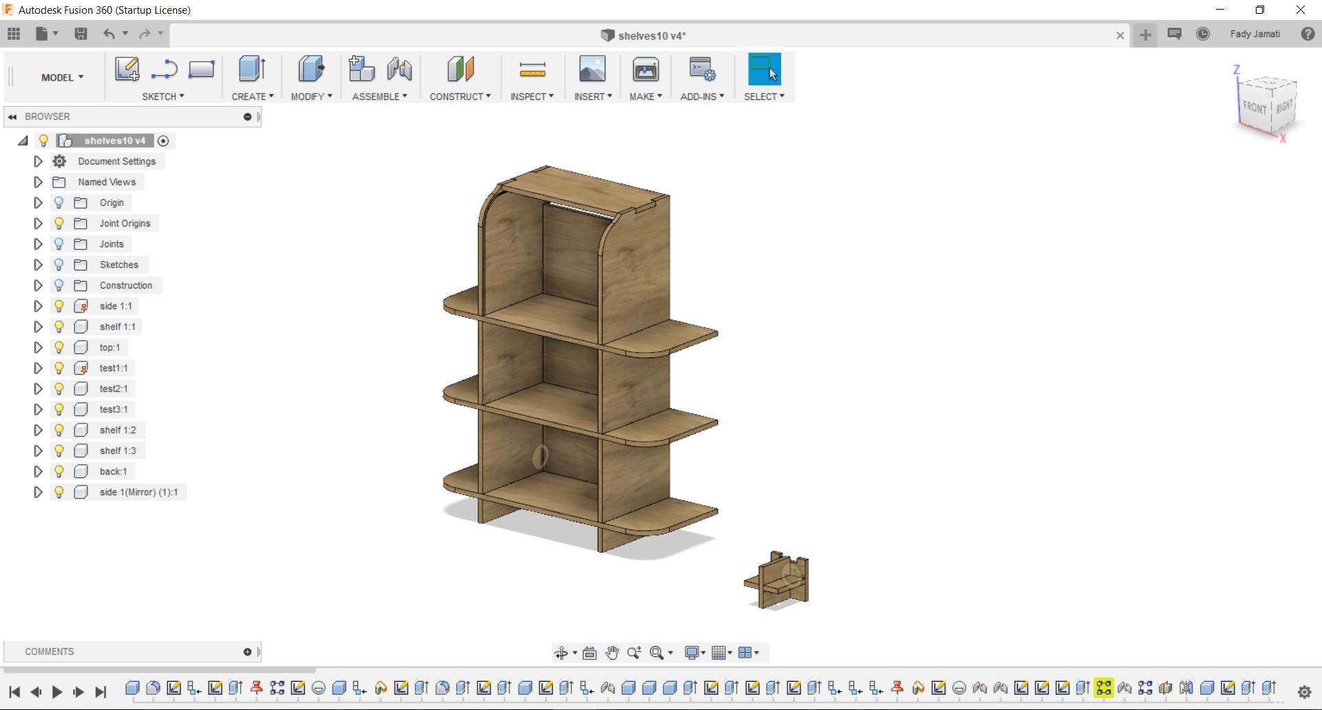
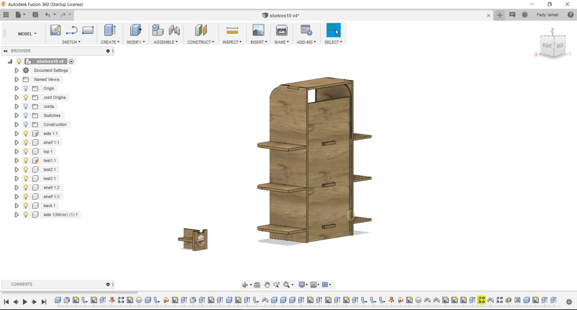
Design
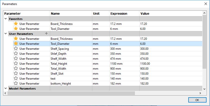
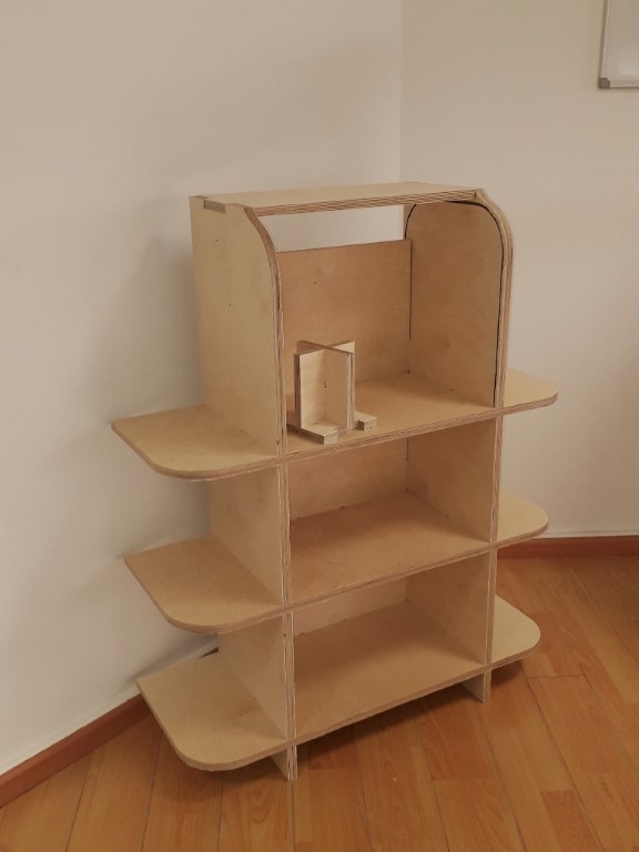
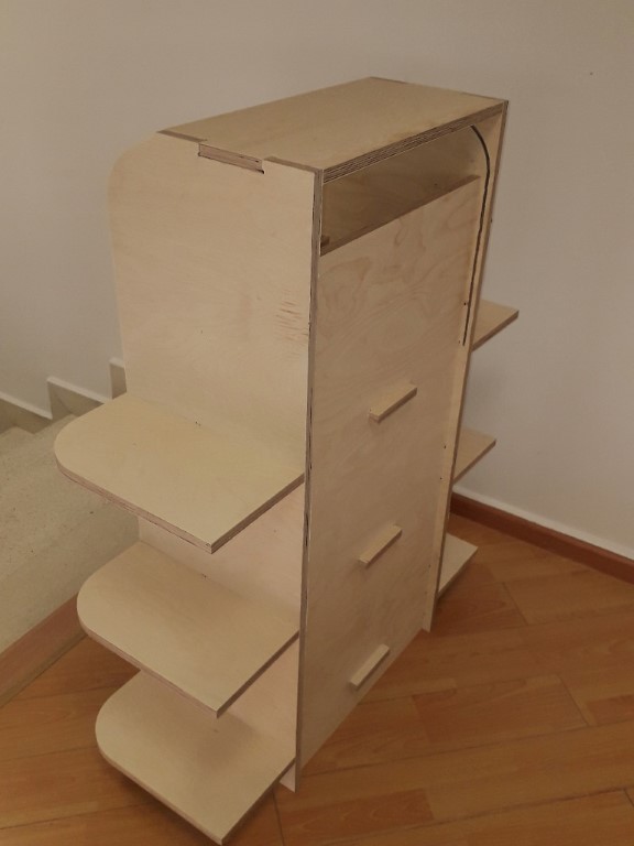
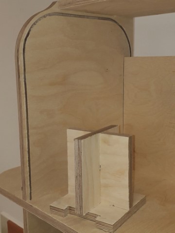
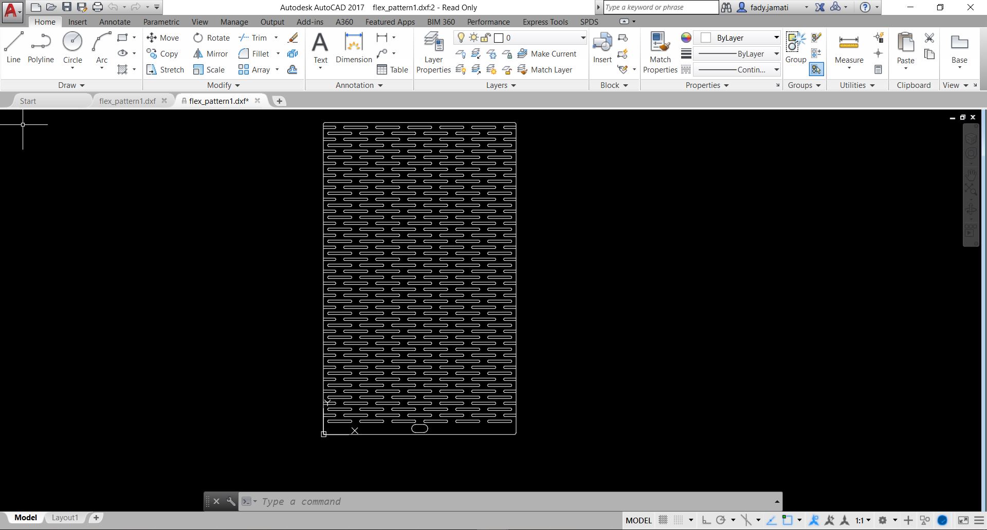
I did a parametric design for a shelving unit on fusion 360. The main parameters are the Board thickness and the Tool diameter. The design includes a groove on the top shelf which starts on the front sides and ends behind the back panel. The sliding element was meant to be a complementary part cut in a flexible pattern with a thinner board (not completed yet). The side joints are hidden since they fit in pockets on the side elements. It is not necessary to make pockets for the joints in the back since the back side will not be visible. The top joints are visible because it seemed risky to mill pockets too close to the edge.
Computing the feed rate
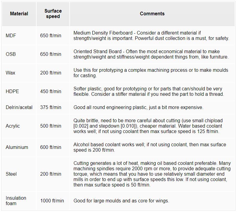
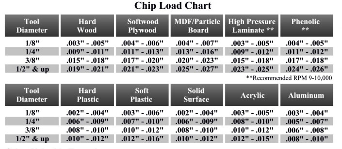
We have used plywood for our projects. Using the tables below we have computed the Spindle Speed and the Feed Rate. We used the MDF value for surface speed considering that it is the closest to plywood.
- Computing the spindle speed:
Spindle Speed (rpm) = [ Surface speed (feet/min) X 12 ] / [ Pi X Tool Diameter (inches) ]
Spindle Speed (rpm) = 650 X 12 / 3.14 X 0.24 = 10,345
We will round the result to 10,000RPM
- Computing the feed rate:
Feed_Rate (inches/min) = Spindle Speed(RPM) X Number of Flutes X Chip Load (inches)
Feed_Rate (inches/min) = 10,000 X 2 X 0.012 = 240
Testing
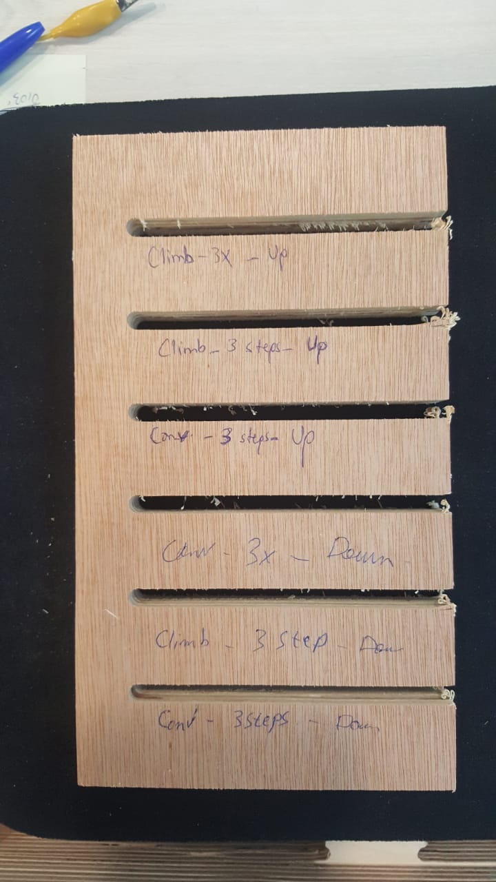
- Test1: Test with up and down flutes (x2), steps and full cut (x3), climb and conventional
The step cuts were cleaner than the full cut. No visible difference for the other parameters
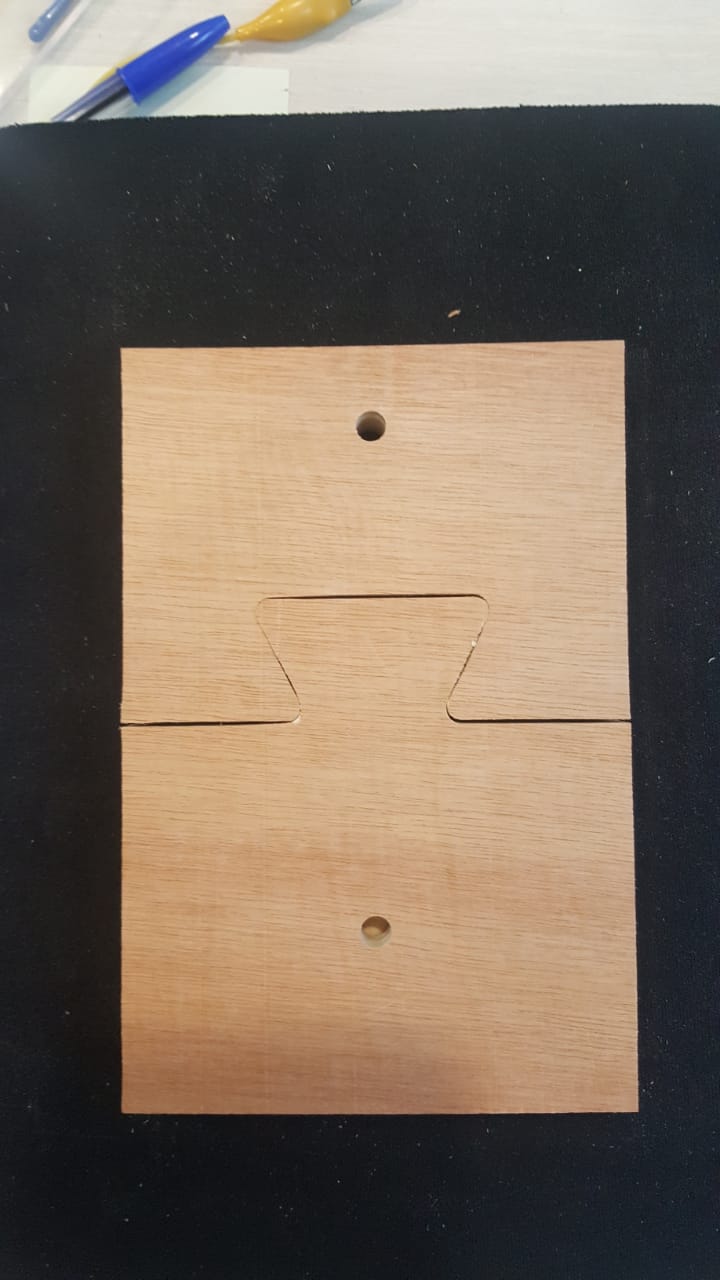
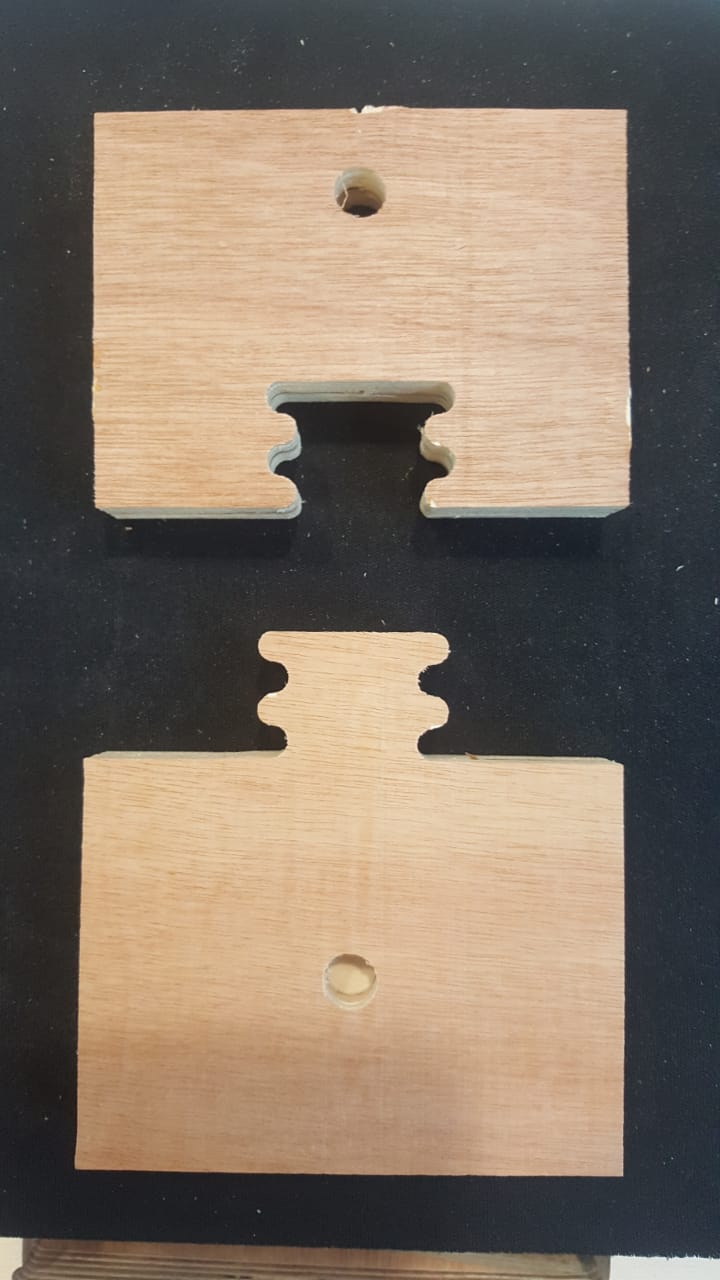
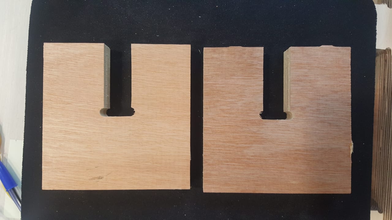
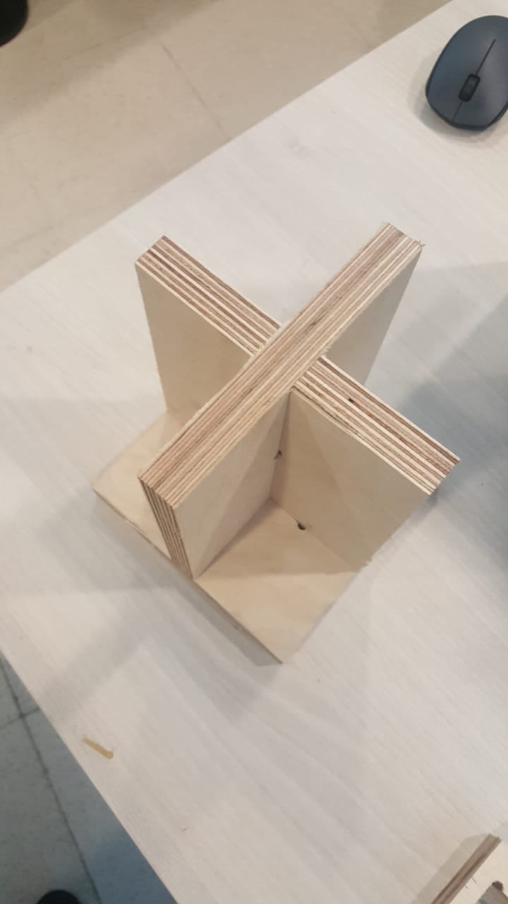
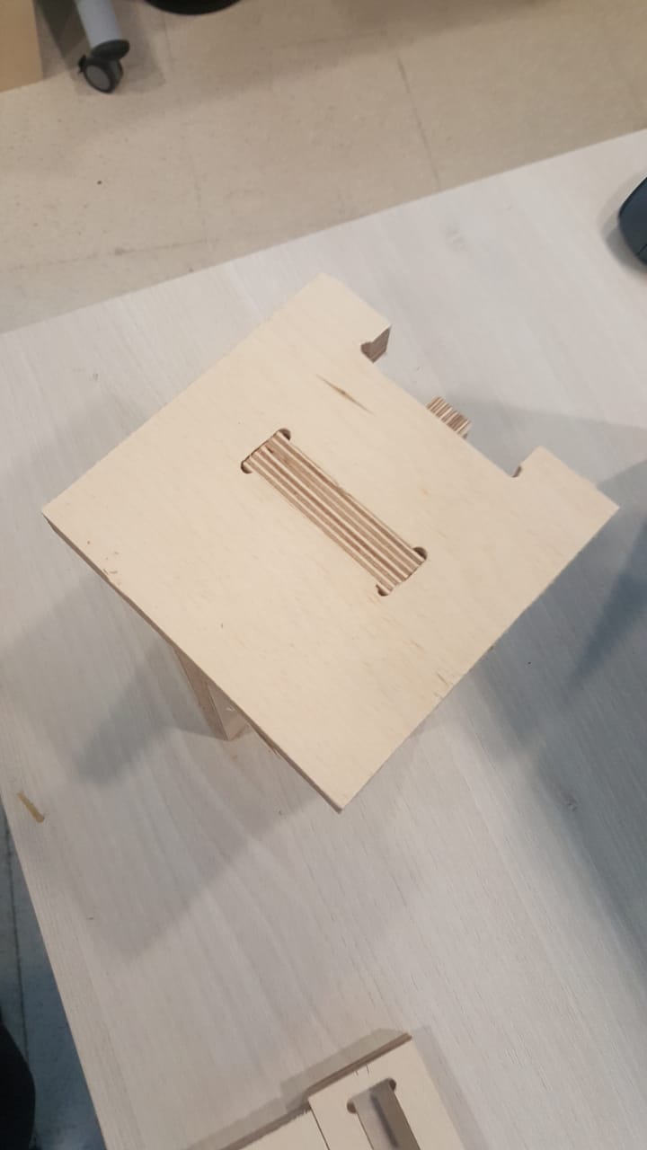
- Test 2,3,4: Test for different types of joints with a 18mm plywood test board
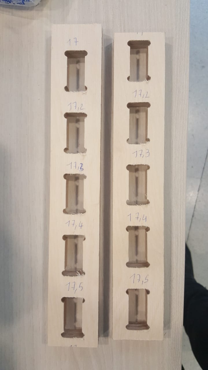
- Test5: Tolerance test with a good plywood board
The plywood board was rated 18mm. Precise measurements showed it was 17.7mm. The best fit was for 17.2mm. So the cut takes 0.25mm on each side.
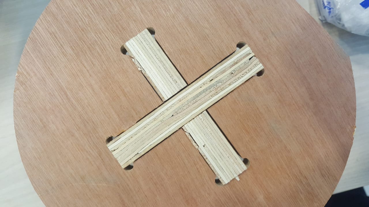
- Test6: Confirmation test for joints with 0.25mm clearence
Machining
Create file for inside cut (18.1mm depth steps) with ramp, and tabs
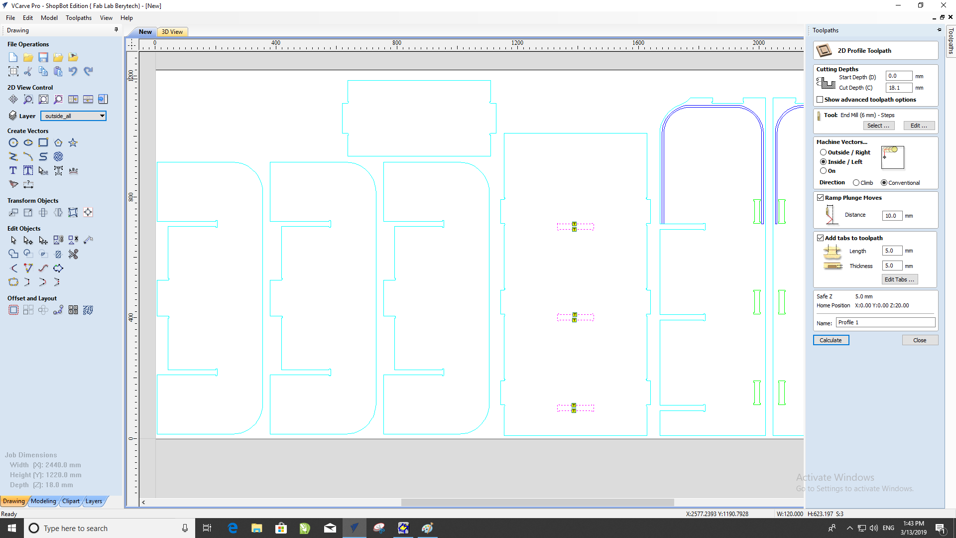
Create file for outside cut (18.1mm depth steps) with ramp, and tabs
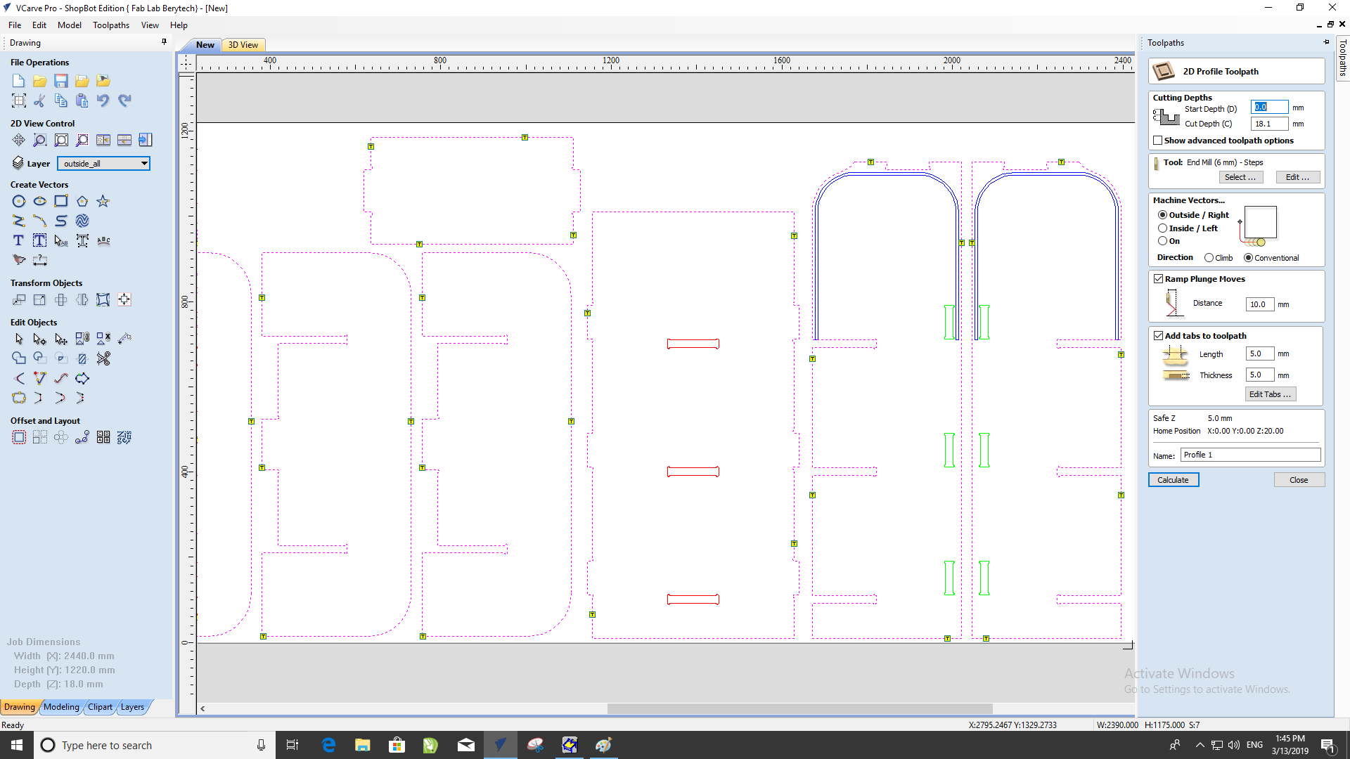
Create file for pocket cut (11.2mm depth steps) with ramp, and tabs
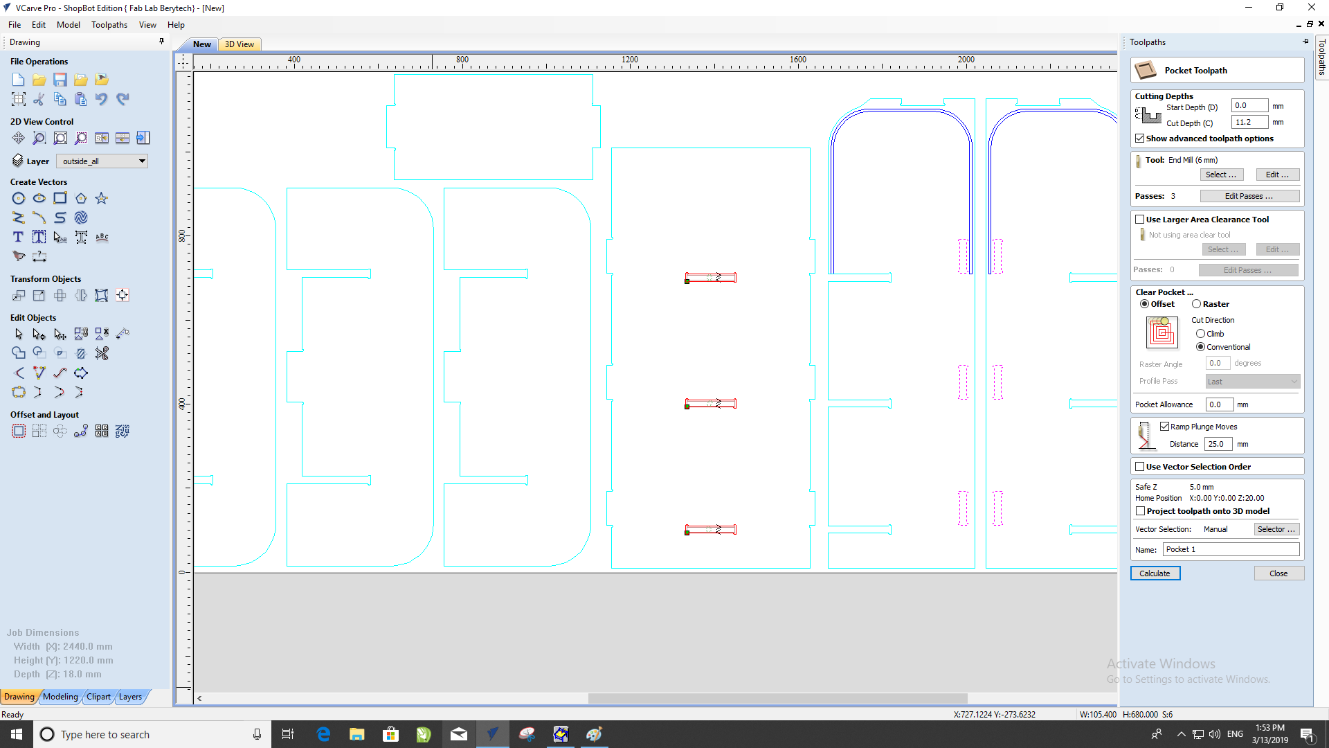
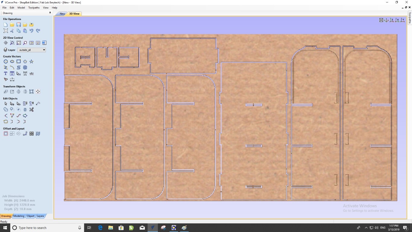
Simulate cutting and pocketing path
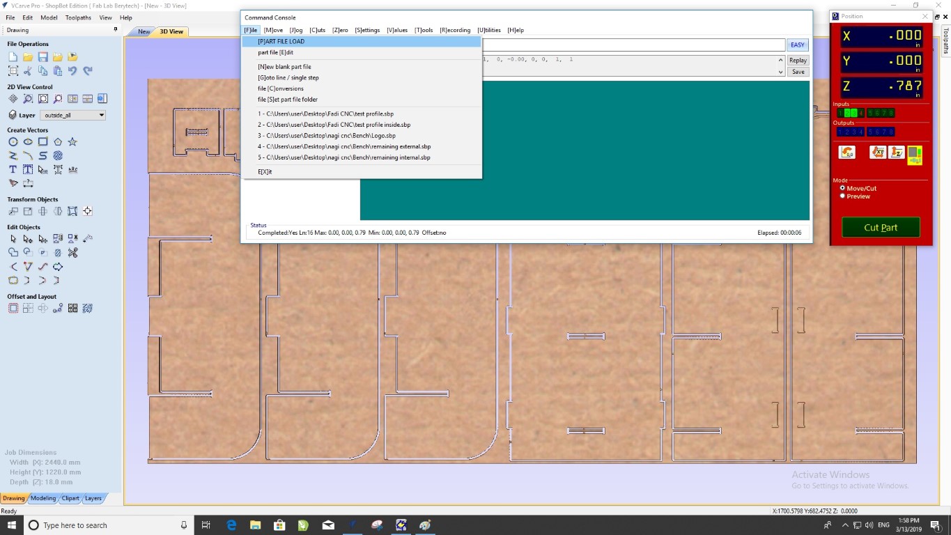
Zero X, Y, and Z axis on the CNC machine, then start loading files to the CNC command console
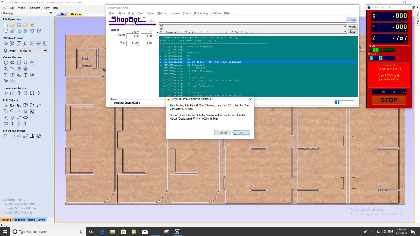
Once the file is loaded start router, wait 3min the first time to warm up the thread, then start.
CNC machine in operation

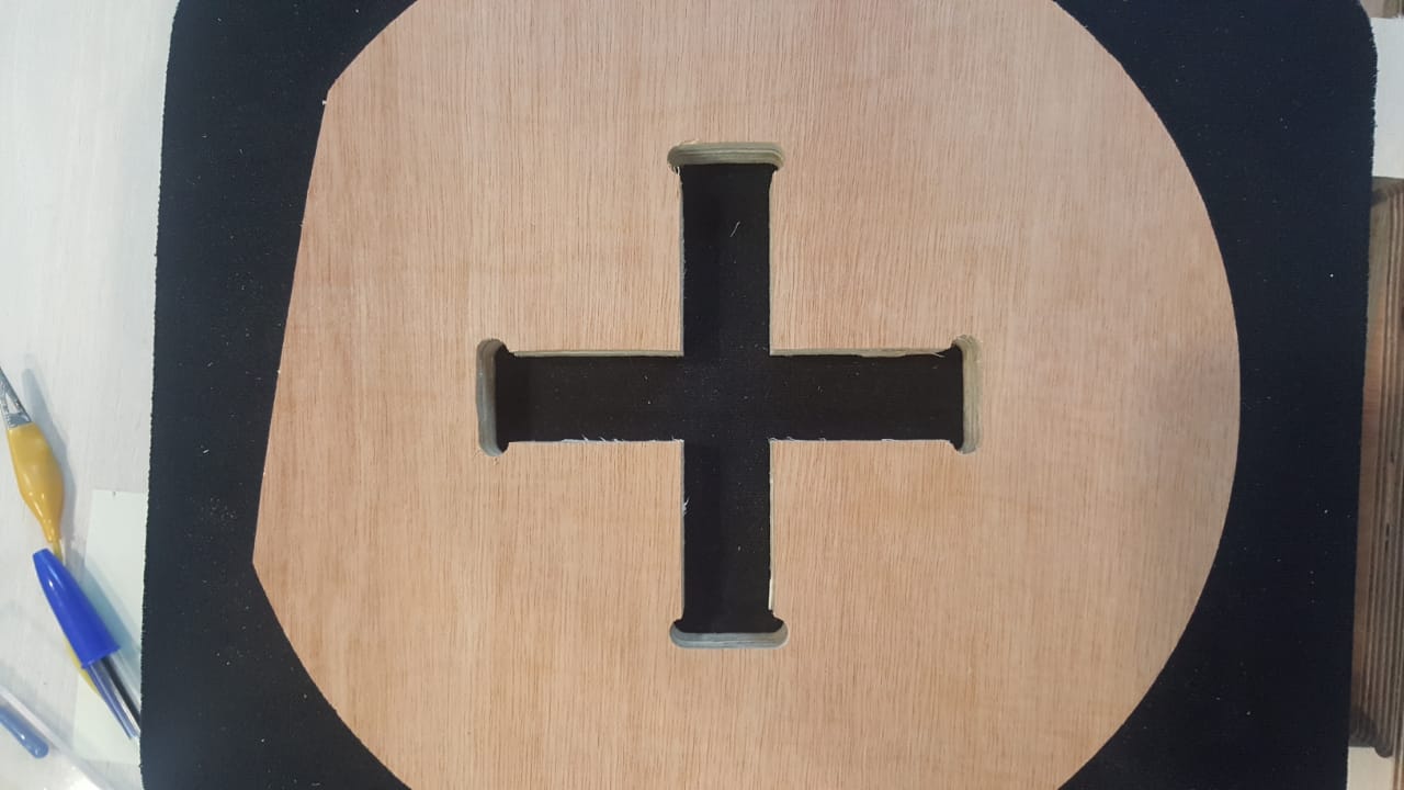
Result
Still to come
The design includes a groove for a sliding door with a flexible pattern. This work will eventually be completed later