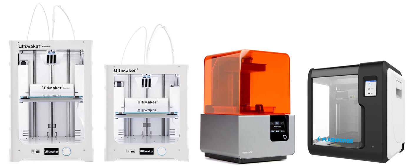
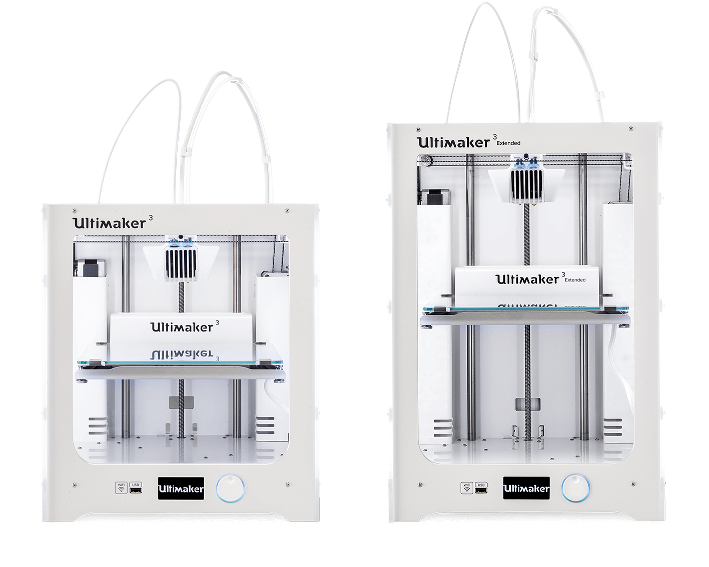
A Precision/Orverhang test was performed on a Ultimaker3 3D printer and Cura slicer. The settings used are using are the preset standard settings for a normal quality print with PLA filament. Mainly:
- Layer height: 0.15mm
- Wall thickness: 1mm
- Infill Density: 20%
- Print temperature: 200degC
- Build plate: 60 degC
- Print speed> 80mm/s
- Printing temperature:200degC
- Support: Non
- Build pate adhesion type> none
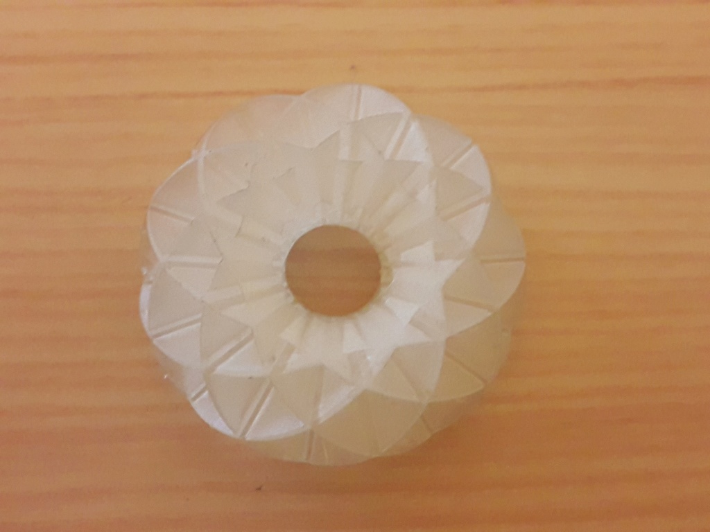
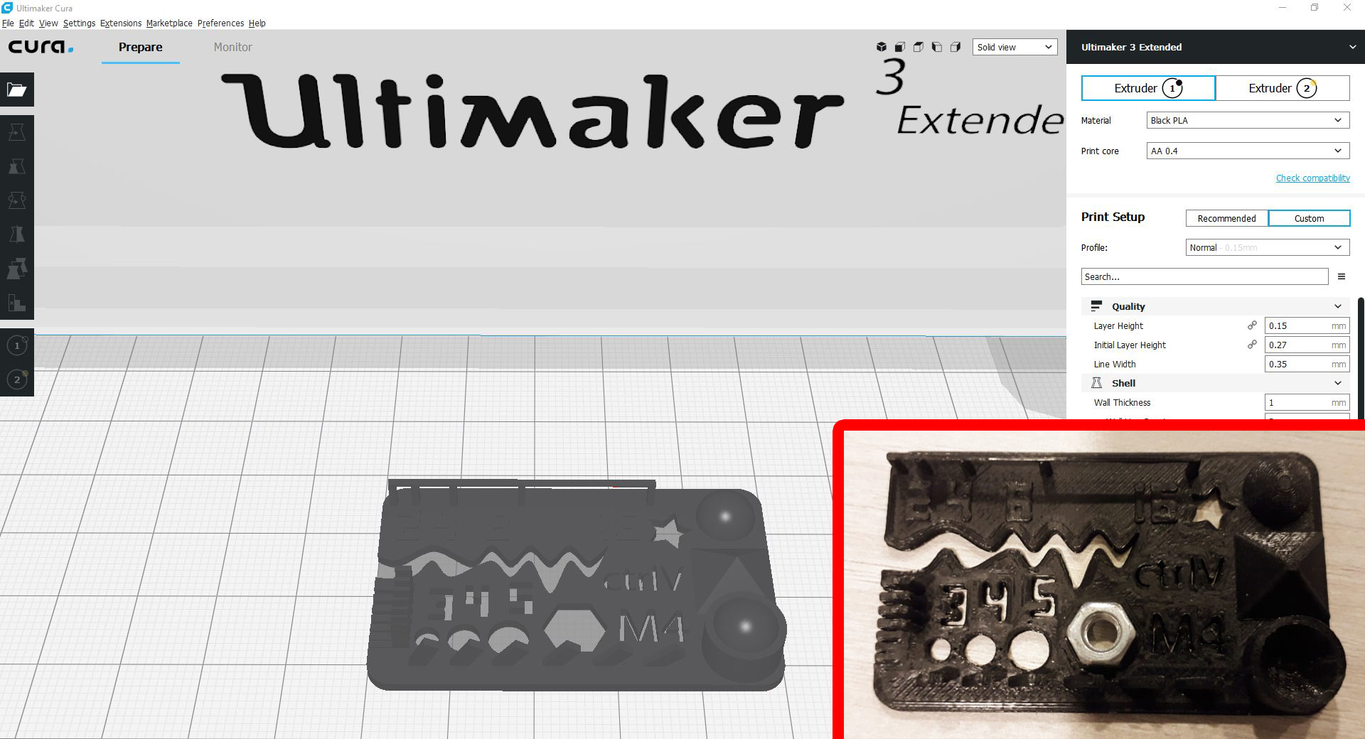
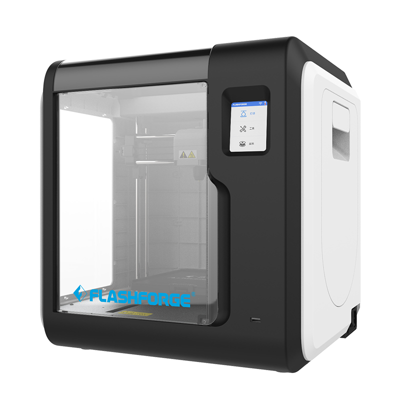
For The Precision/Orverhang test we downloaded a small test file from thingiverse. It just took 40 min to print and gave very decent result
- Hole size (3 holes 3/4/5mm):Good precision
- Nut size (M4 Nut should fit perfectly): It takes a hard push to fit
- Fine details (pyramide, cone, all numbers): Good
- Rounded print (wave, half sphere): Good
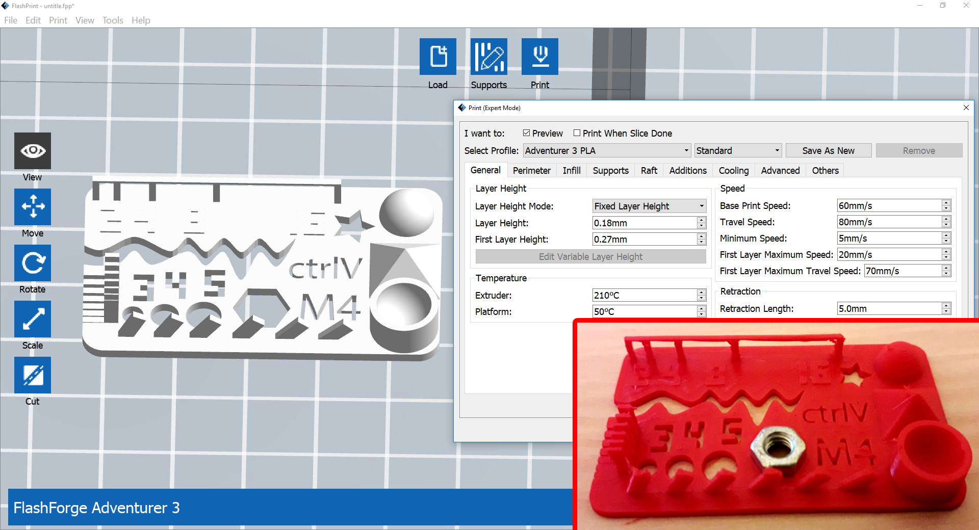
- Minimum distance and walls (0.1/0.2/0.3/0.4/0.5/0.6/0.7mm): Only 0.7 and 0.6 are fully separated
- Overhang (25°/30°/35°/40°/45°): Pass
- Bridge print (2/4/8/16/mm): Pass
- Surface (all the flat parts): Good
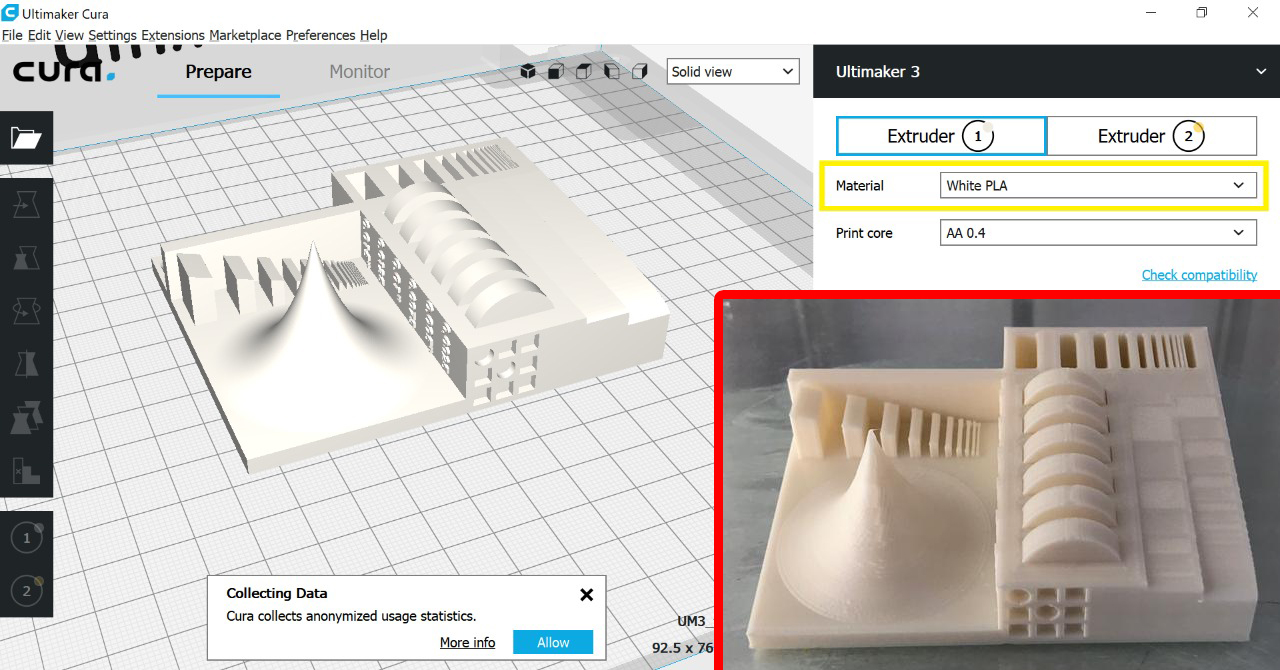
A Tolerance/Precision test was performed on the Ultimaker3 Extended 3D printer and Cura slicer. We downloaded the Tolerance/Precision test file from thingiverse. The settings used are as for the previous test with PLA filament. The test features moving hinges of varying tolerances ranging from 0.38mm up to 0.635mm. It also features thin walls and wells ranging down to 0.016mm
- Thin walls and wells: Clean
- Range of curvature: Good
- Sloping surfaces to test z-axis resolution: Good
- sharp peak: Very Shapr
- cavity: Clean
- moving hinges of varying tolerances: All were stuck
I'm sceptical about the results of the tolerance test. I've used a different tolerance test for the Flashforge 3D printer (next paragraph) and the clearance was ok for 0.4 and 0.5mm. This could be a design issue. I'm not sure the design of this test is not proper for tolerance. So I would say the tolerance test was inconclusive.
.jpg)
.jpg)
.jpg)