

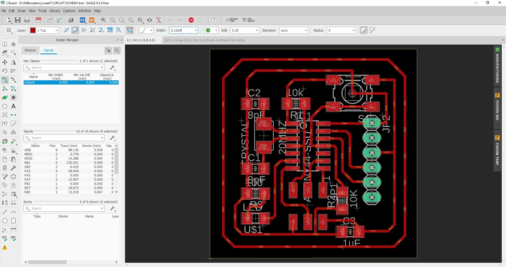
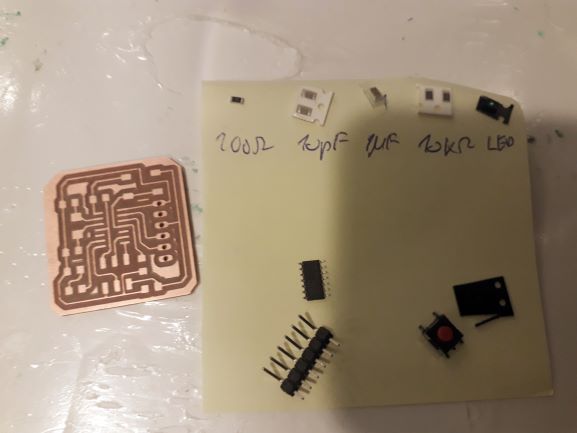
My Hello board includes a push button and an LED in addition to the FTDI and ISP pin headers in th original designers. It also includes a 20Mhz crystal with to 10pF capcitors; a 1uF capacitor between ground and VCC; a 100 Ohm capacitor in series with the LED, and 10 KOhm pull down resistor in series with the push button. I drew the schematics on Eagle

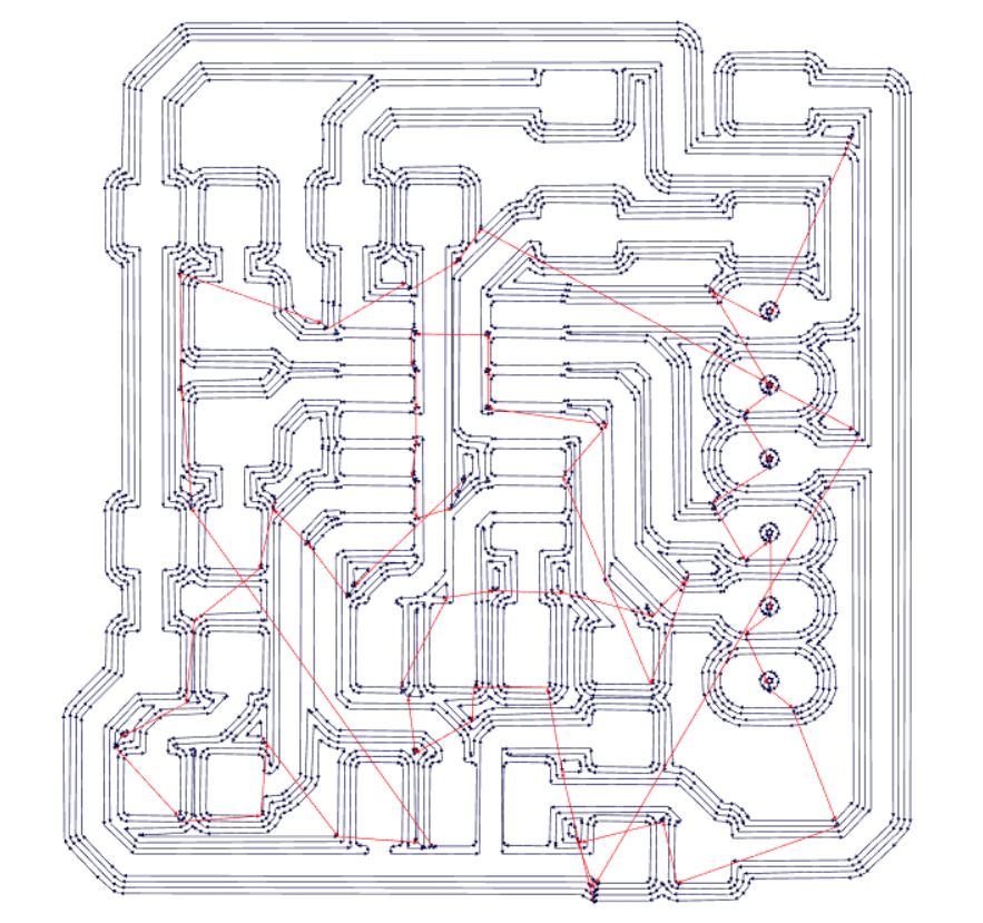
I tried to keep the PCB drawing compact but wide enough to avoid bridging problem in welding, and I made shure that the spaces between traces are wider than the 0.4mm milling thread. The traces and the clearance are 16 mil. I found all the needed components in the FAB library except the FTDI in-hole component which we used to make soldering easier.
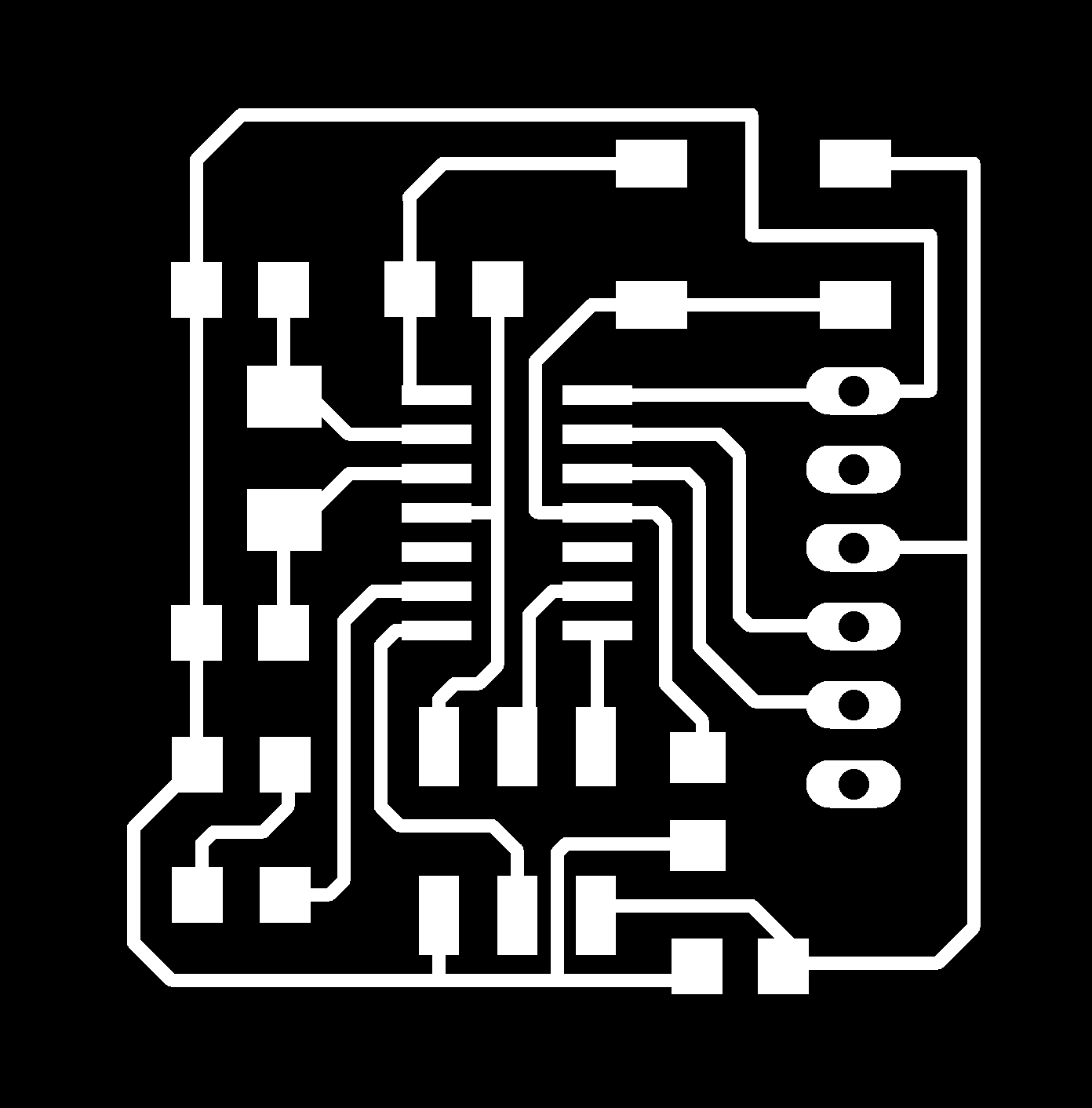
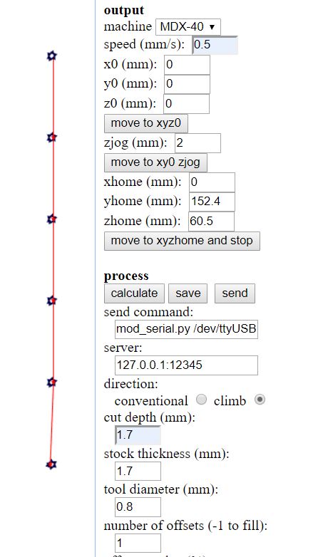
After exporting the images in PNG format from Eagle in a monochrome mode and with 1000 PPI, I edited them with GIMP. Last time, in electronics production week, I used Photoshop because that's what I'm used to but GIMP works just as fine for this purpose. The only changes (from week5) in the settings of the Fab Modules G-code generation the offset kept at 50% rather that 70% to make the clearance wider.This time I have also used the milling machine to drill holes in the board. For drilling I used a 0.8mm thread with the setting for outline. Given that holes are about the same dimension the machine will just drill a hole in these settings
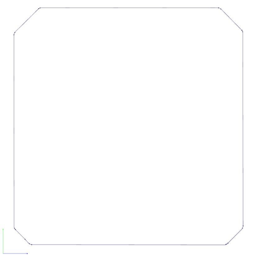
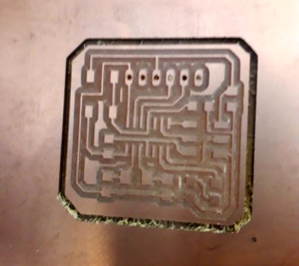
For milling we used 0.4mm thread, for cutting a 0.8mm thread, and for cutting a 1.2mm the result was clean as it should be, and soldering went well. The first step was to mill traces, then drill the holes, and then cut the outline.
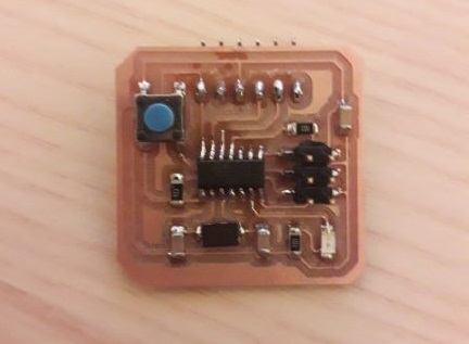
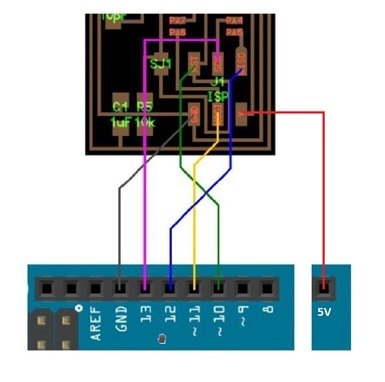
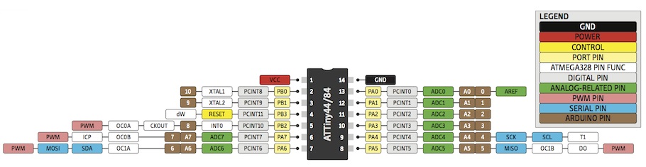
Using the Arduino examples, I put together a small code which commands the LED to blink when the push button id pressed. This is easily done by combine the blink sketch and the push button sketch provided as examples in the Arduino IDE software. Then I just had to change the number of the pins to make it work with the Attiny44. I uploaded the code to my Hello Board with the Arduino programmer with the connection displayed in week5 in addition to the VCC connection. The first step is to connect the arduino board and to load select it in Tools, select the port, and upload the ArduinoISP sketch from examples. Then disconnect, connect the hello board to the Arduino board, reconnect to the PC, select Board and processor as Attiny44, select clock, select programmer as ArduinoISP, burn Bootloader, and finally upload my Hello_bord sketch. It worked fine.
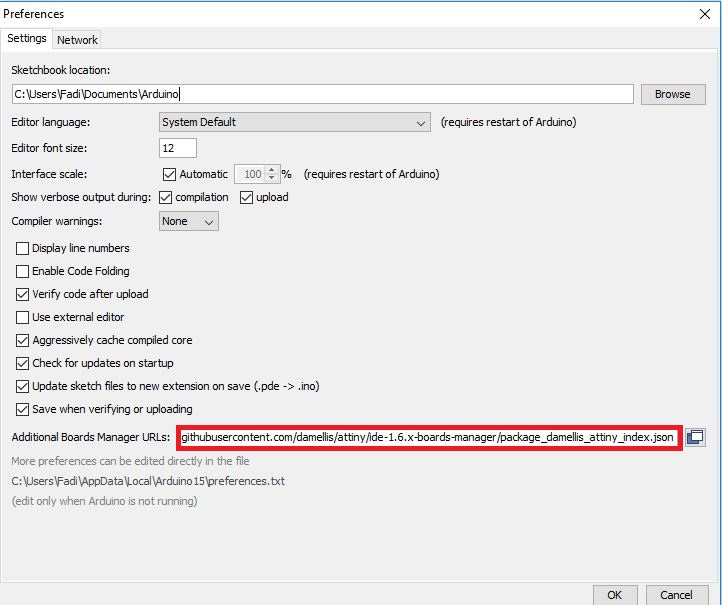
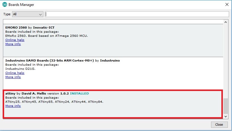
To programme your Attiny44 with the Arduino board you'll need to install the Attiny44 plugin in the Arduino software. The steps to do this are:
Once that is done you can use the Arduino Board as a programmer for the Attiny 44. To programme the Hello board using Arduino follow these steps: