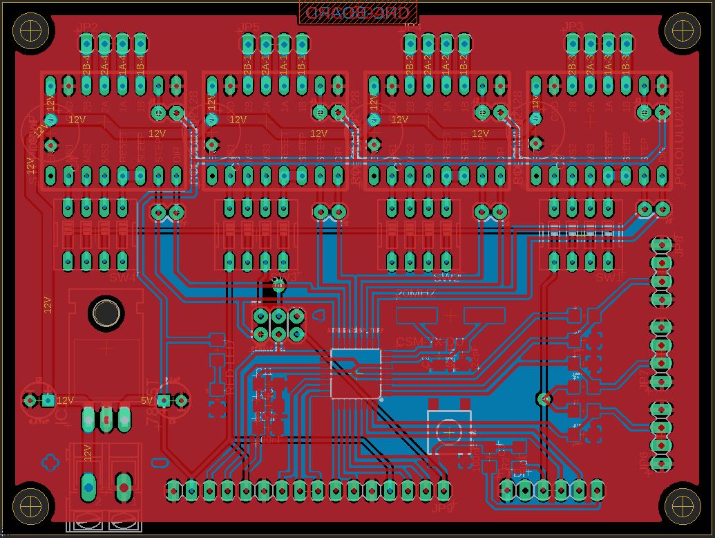
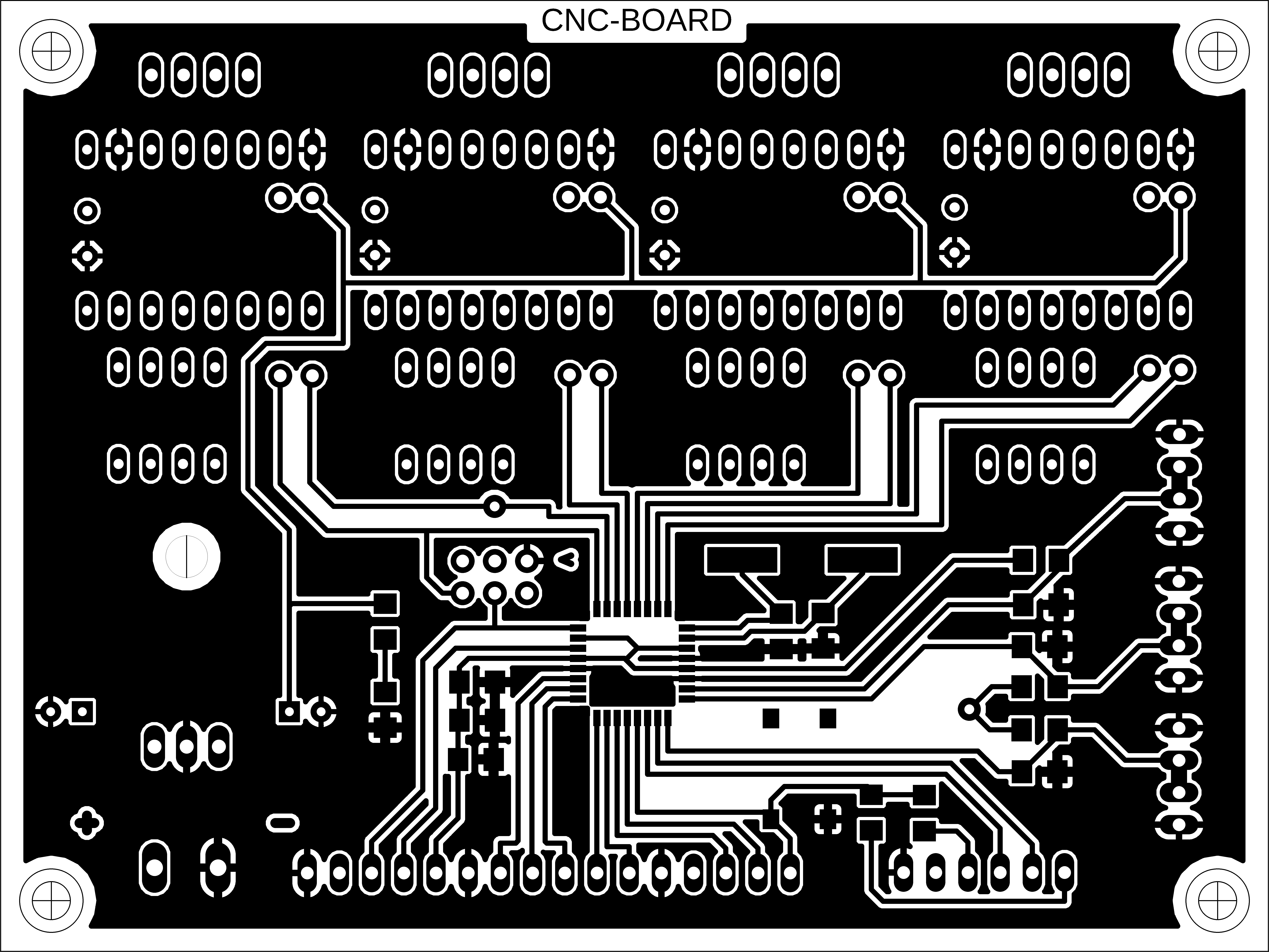
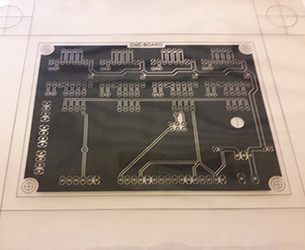
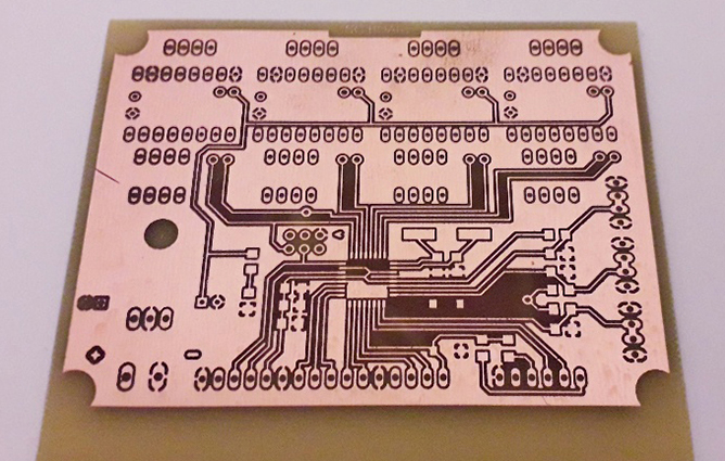
Top layer
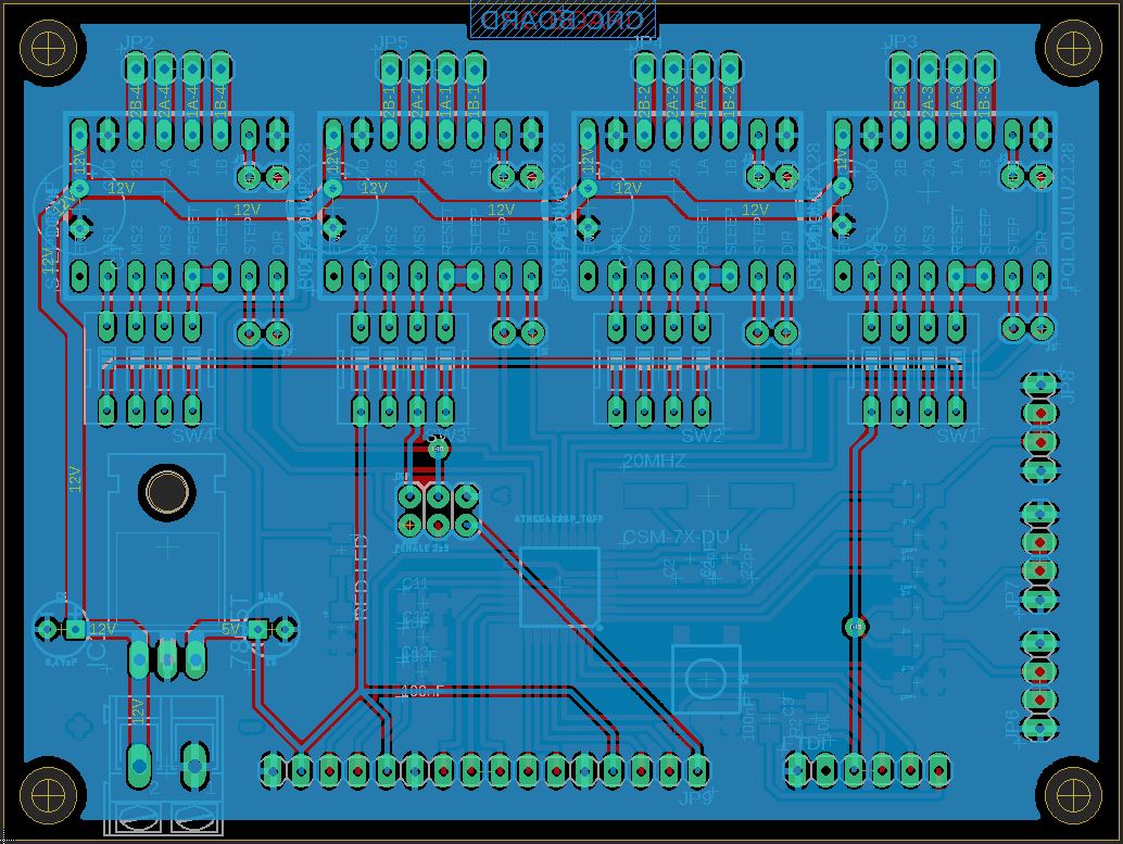
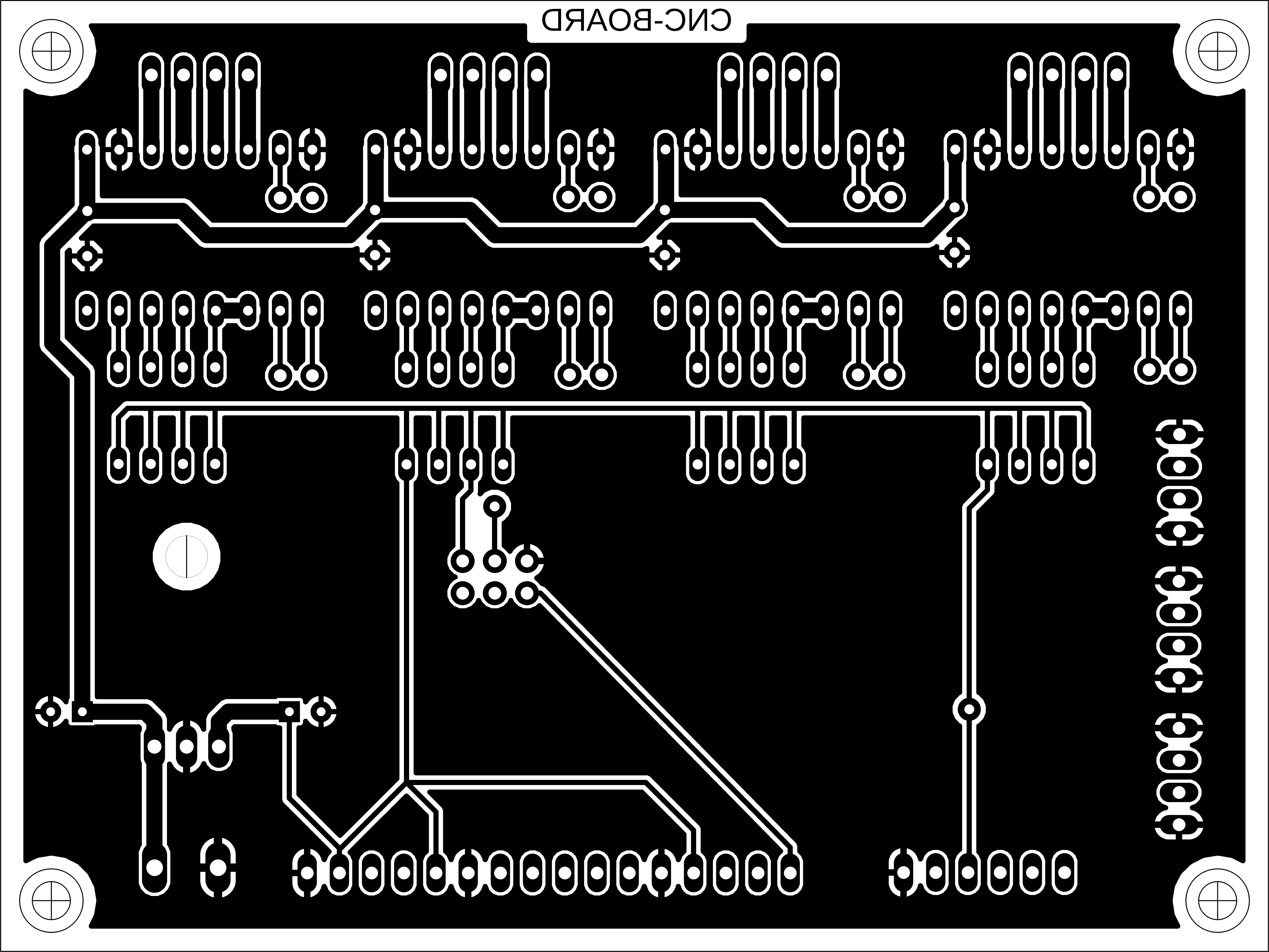
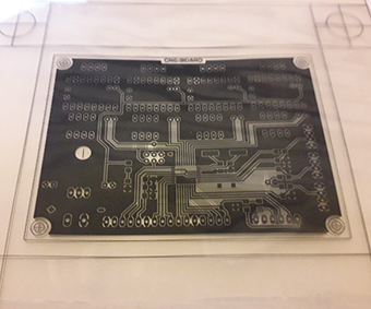
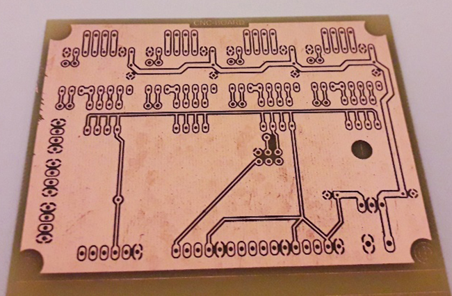
Bottom layer
For output devices, I designed a circuit on eagle that includes a voltage regulator,connections and 100uF capacitors for four Pololu stepper motor drivers, connections and filtering capacitors for four limit stwitches, ISP pins, FTDI pins, and several multipurpose pins to connect inputs such as a joystick or LCD threw I2C bus. It also includes DIP switches for micro-stepping.
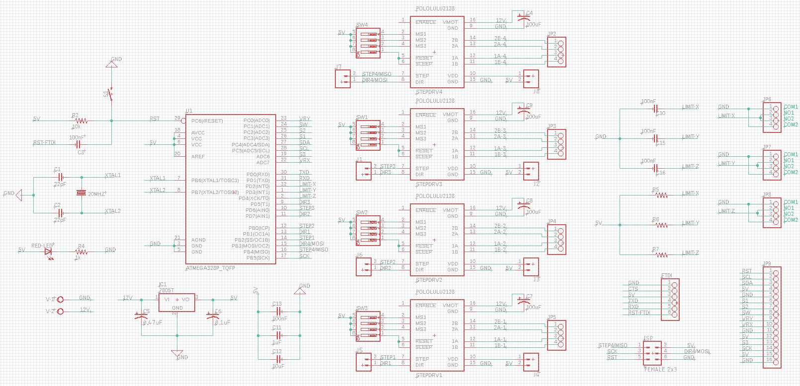
The design is a double layer with ground plane
Top layer
Bottom layer
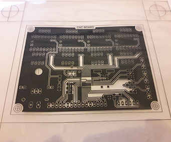
For production I experimented with etching. I printed the top and bottom PCB layouts on transparent sheets with a laser printer and superposed them
Top layer
Bottom layer
Superposed layers
The printer layouts were placed on the two sides of a double side photosensitive board. Each side was exposed to a UV light for a couple of minutes and then placed in the developer solution for a few minutes. The action of the developer is to remove the areas exposed to the UV light.
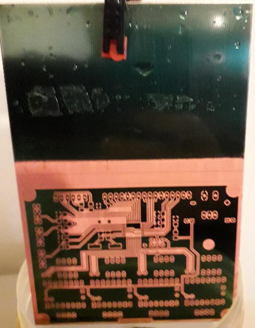
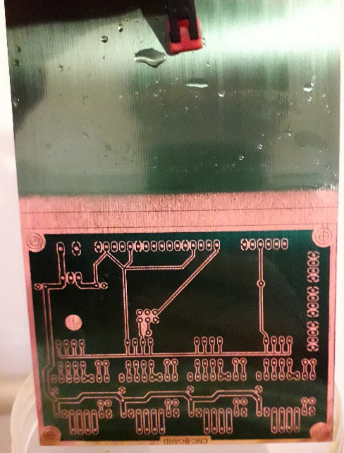
The next step was to place the board in an etching solution for half an hour. The etching solution removes the areas not covered by the ink. The etching solution was safely stored after usage.
The board includes two vias which were soldered using copper wire, and the pin headers were often used as vias as well, so many are soldered on both sides.
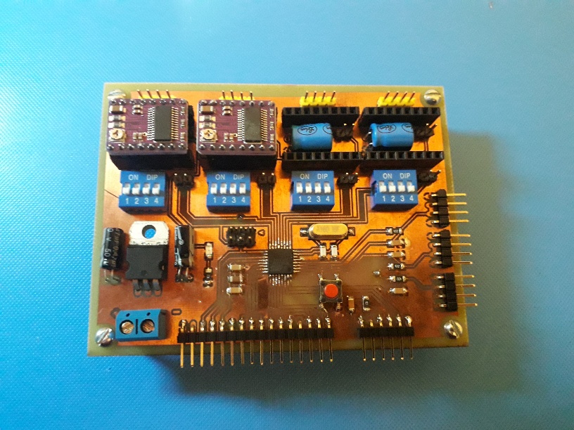
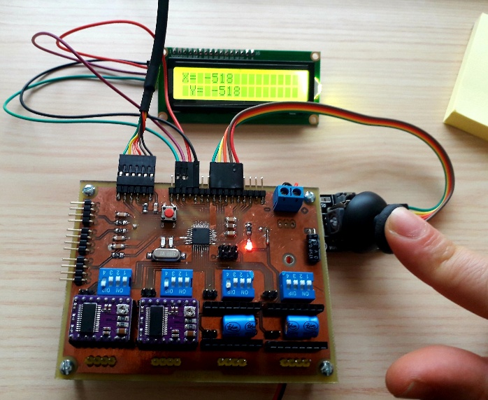
I had a problem with the voltage regulator, it was getting very hot even without the motors, and drawing high current. I couldn't program the Microcontroller getting rc=-1 connection error. I had to remove the voltage regulator and power the motors and the microcontroller separately to get the board working. The code is meant to control two stepper mo
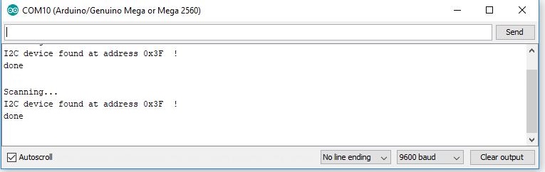
I also connected my board to an LCD screen via a I2C module. To find the adress of the I2c module I mused a I2C scan programme found in an Arduino library