Menu
HomePrinciples and Practices
Project Management
Computer-aided Design
Computer-controlled Cutting
Electronics Production
3D Scanning and Printing
Electronics Design
Computer-controlled Machining
Embedded Programming
Molding and Casting
Input Devices
Output Devices
Interface and Application Programming
Networking and Communications
Mechanical Design
Machine Design
Wildcard
Applications and Implications
Invention, Intellectual Property, and Income
Project Development
Final Project
Week 14
Networking and Communications
Week Assessment :
Design and build a wired &/or wireless network connecting at least two processors.
For this assignment, we have to connect two or more boards in serial communication. The minimum for this week is to do serial bus communication. what does serial bus communication? basically is the process of sending data at a time, sequentially, over a communication board or computer. we can imagine that the cable is a real Bus and student on the bus are data and each bus station is board. I did a couple tries until I get it.
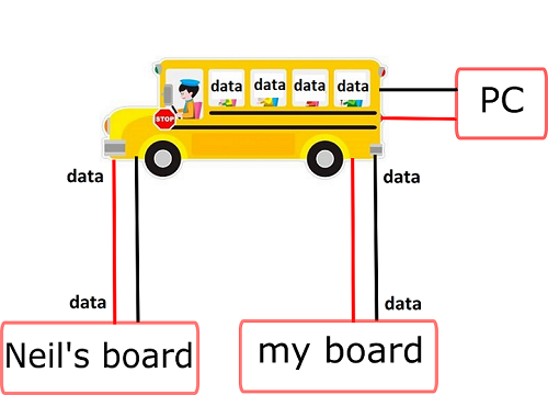
This is my first try
When I was looking for what did the previous student do. most of them they used Arduino board.I looked at Sachin Salim page from India and I download his code so I can modify it later. I will not use the commercial Arduino board. I will use my own board beside Neil's board. I research in google how to communicate two board and I found this tutorial when I did verify the code this error message appears. I did not understand this error message so I asked Wendy to help me. I found that I did not burn a bootloader. I have to burn the bootloader for every new board that I creat. the other issue was I have Arduino IDE (Windows Store) version, so I have to reinstall Arduino IDE.
This is my code
This is my first error message
Then I understand why this code did not work because Attiny 44 does not support I2C communication and I know that from Duaa in our regional review. Attiny has something similar called USI (Universal Serial Interface) and SPI (Serial Peripheral Interface). If I so the datasheet I will notice that earlier. Most of the Now I am aware more about how important is the datasheet and it should be the first thing that I should look at.
Here is what they mentioned USI in the datasheet in page 120.
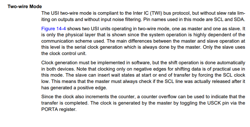
The other error message does not relate to this week code.It's related to Interface and Application week.
This is the error message
This is my second try
Anyway, I used my board from electronics design week to be my master and the board of output devices week as my slave beside Neil's bridge board as supply
My friend Eidha he helped me. I used his code and I did some modification in the code. In my code the button in the master board will control the LED in slave board. basically, I will connect the FTDI pins on Neil's board and ISP will connect Neil's board and my master board and my slave board. While the FTDI in the master VCC and GND will be connected to the slave VCC and GND, but the TX in master board and RX in the slave board.
All these boards are connected the three ISP headers through daisy cable. I used MOSI and MISO as TX and RX. so I did simplex communication. When I was studying, I learnt there are three types of communication which are: simplex, half duplex, and full duplex communication. Simplex means that the master board gives the orders to the slave board. While in half duplex means that the master board sends the order for the slave and the slave sends something to the master board to confirm receiving, only one at a time can send in the serial bus. In full duplex, the master and slave can send to each other at the same time, a good example for that is the phone.
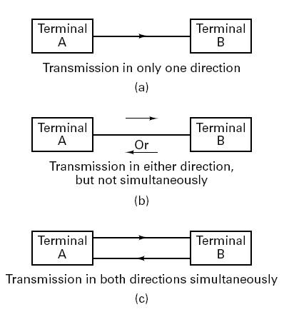
So what I did was simplex communication. To be able to use the serial communication in Attiny 44 I had to add a library that calls SoftwareSerial in my code. Then I initialized my RX and TX pins.

I designed my system to have 2 master board and one slave board.
there is the master 1 code
This is the master 2 code
This is the slave code
This is the result
It works only with one master, not two master board which means that there is a traffic in the serial port. I did not find here this traffic happens while my else statement is just a delay which is send nothing to the serial port.
Finally, I did it and I implement it in my Final Project
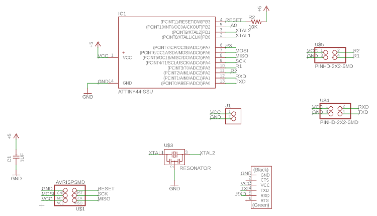
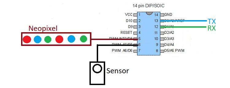
For the final project, I developed my communication code to be able to use it for my final project . I designed my boards in Eagle. My master board has one pin for Neopixel which is physical pin 5 and the sensor (MQ2) to physical pin 6. For the communication my TX in physical pin 13 and RX on physical pin 12. The two slave boards has the same connection as the master board but without the sensor and there is a header under the FTDI for TX and RX, so I can connect the two boards in the same wires. To see what final project see my summery page
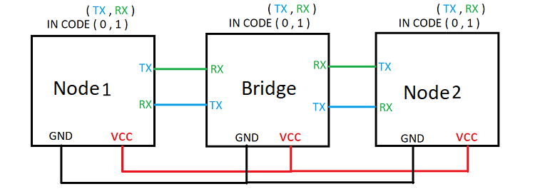
This is schematic for master board. all the files in Neoguidance.zip at the bottom of the page.
This is schematic for slave board
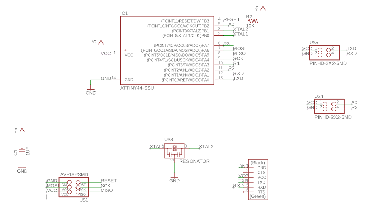
The reason why I chose pin 8 for Neopixel is that I found that Neopixel only works with port B in Attiny 44. I did a search to find the answer but I found nothing if I had time I will investigate more deeply about that. Anyway I struggled a lot with the communication because the node schematic and PCB did not save which I found difficult to get the communication works. I'm glad that we have Eidha he sit with me and he helped me to troubleshoot. In the code, the side was to get the side arrows shows blue light which will be the normal state. In case if the sensor detected a smoke this side arrows will change the colors to green to show that direction and the cross in the middle will appear in red. To program Neopixel, I had to download the library for Neopixel. In Embedded Programming I showed how to add a library in Arduino IDE.
The bridge is connected with smoke sensor and neopixel strip. the code will read the values from the sensor. If the sensor detects the smoke the bridge will send "1" and "2" to the nodes beside turn the red light. In this code, the bridge will be able to receive from the nodes to conforme reciving. The nodes will send back 'n1' for node 1 and 'n2' for node 2. Then the bridge will know which node is talking.
Node1
Node2
The node boards are connected with neopixel stip. In the normal condition the light will be blue. while in case of fire the light will turn to In the node will not turn on the LEDs unless it gets something from the bridge board I define the node by numbers so each node has it own number which will allow the bridge to control the system by sending the data to the correct node. So I have 2 nodes and I defined this node in this way "n1" and "n2". When the nodes receive something from the bridge the LED will turn on in green. The two nodes will not work at the same time because the bridge send "1" then it waits for a certain time then the bridge send "2". The boards do not know when to talk and when they have to listen, that cause what we call it data traffic. so I have to teach them how to behave and the only way to do that is by coding. so I had to add INPUT_PULLUP for the TX that helps to control the transmit line for the nodes. Which is mean that only one node can send in the transmitting line at a certain time.