Things to do :
- Make something Big
DESIGN
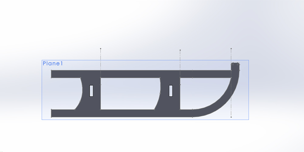
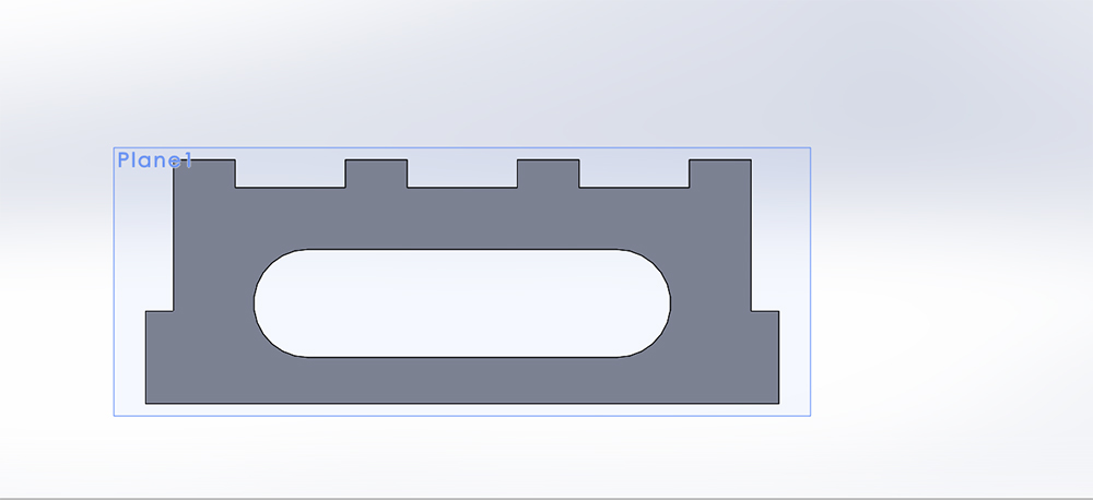
For this week asignment we had to make something Big . I love the snow and snowboarding and I never have enought of it , so I decided to make a sled to use it when the lifts close.I designed the 3 parts that I needed to assemble the sled whit solidWorks.I make it parametric ,to do that I defined all the variables in the first part i created and I exported the file equation.txt,so for the other two parts it was enought to import it in order to have all the variables defined in a single file:tools -- equation -- import -- equation.txt
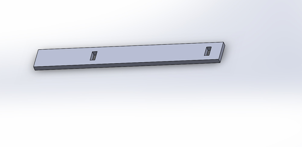
Here are the parts :
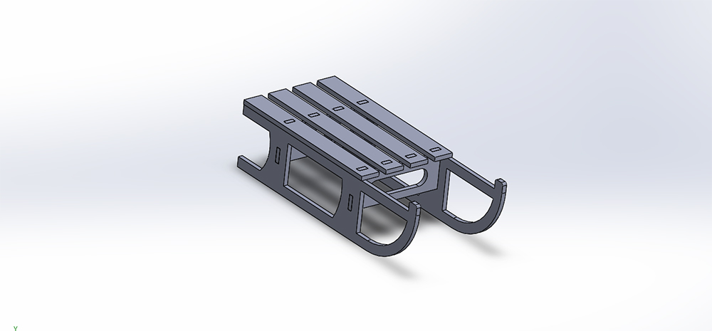
and Here are the Assemble :
From Solidworks , to export as 2D drawing, I saved it as DXF file and selected the face of the 3D model I wanted to export.
Prototyping
I wanted to be sure of the proportions of the sled ,so I laserCutted a scaled version of the project. Every parameters are moltiplied for a variable that I called "scale" ( except "thicknessOfMaterial"). I setted "scale" = 0.25 and "thicknessOfMaterial"= 5.8 mm ( that is the thickness of the plywood that were left from week 3 )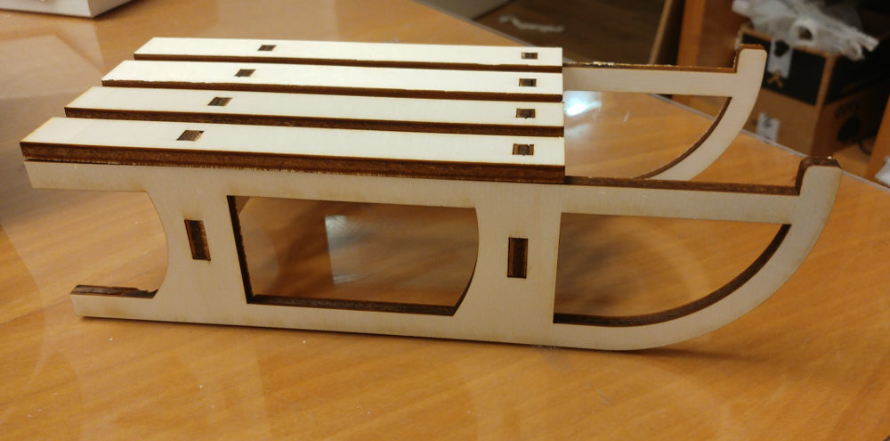
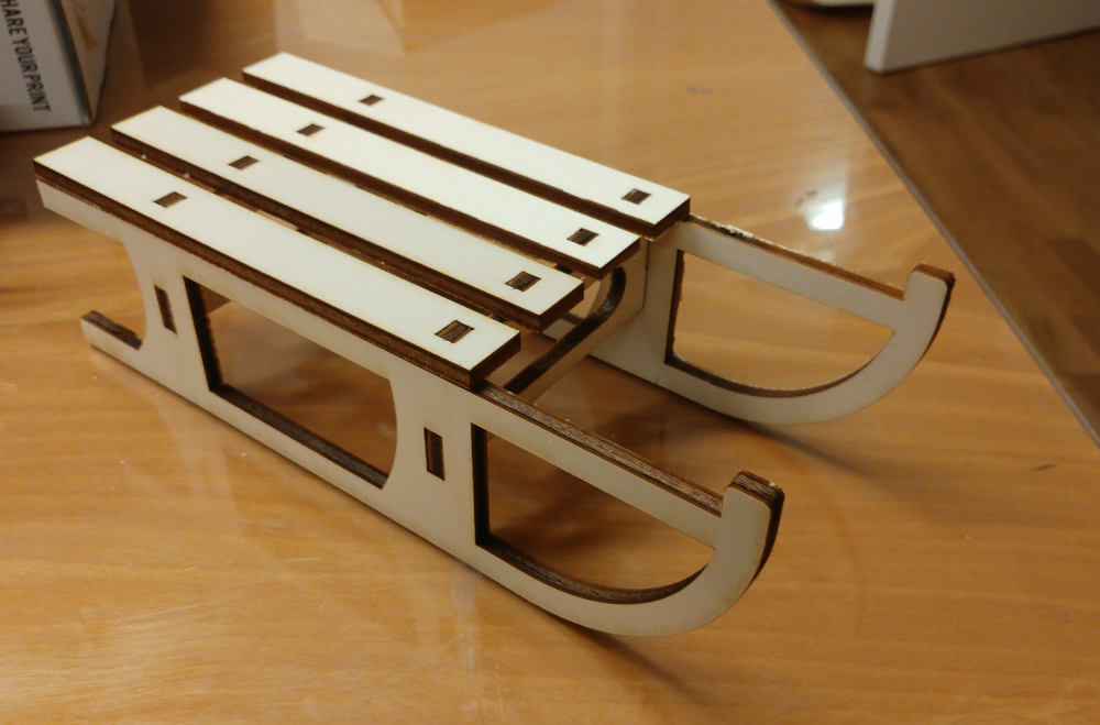
Once I saw the results I was pretty satisfied about it and I moved on making the big sled.
Computer controlled machining
Setting the parameters
The most important parameters that I had to deal whit are :RPM:("Routes Per Minute") indicates spindle speed.
Cutting edges:number of cutting profiles - you can count them orthogonally looking the endmill from the bottom.(quotes from Silvia Palazzi)
Chip-Load: As it said here Chipload is simply defined as the thickness of a chip which is formed during the machining of a material. Chipload is critical because if the chip is the proper size, the chip will carry away the heat promoting long tool life. If the chip is too small, the heat is transferred to the cutting tool causing prematurely dulling. Too high of a chipload will cause an unsatisfactory edge finish, or part movement. I also found very usefull this video (or this )to understand what and how much important is the chipload.
FORMULAS: ( cutting edges = flutes )
Chip Load = Feed Rate / (RPM x # of cutting edges)
Feed Rate = RPM x # of cutting edges x chip load
Speed (RPM)) = Feed Rate / (# of cutting edges x chip load)
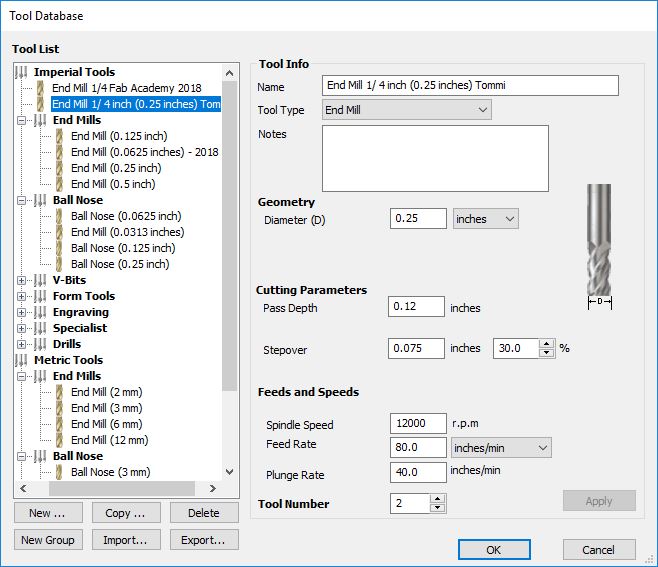
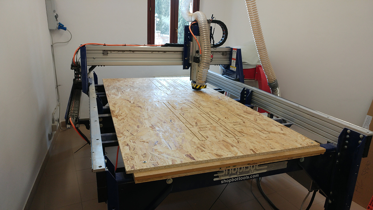
Our machine is a ShopBot PSR Alpha it's very powerful and require a lot of carefulness while using it. I used an Onsrud 1/4 flat , 2 flute , end mill to do every step of my cut.
I read this table to have an idea of the chipload I had to use : (I highlighted the end mill I used)
Hold the left button on the images to zoom in
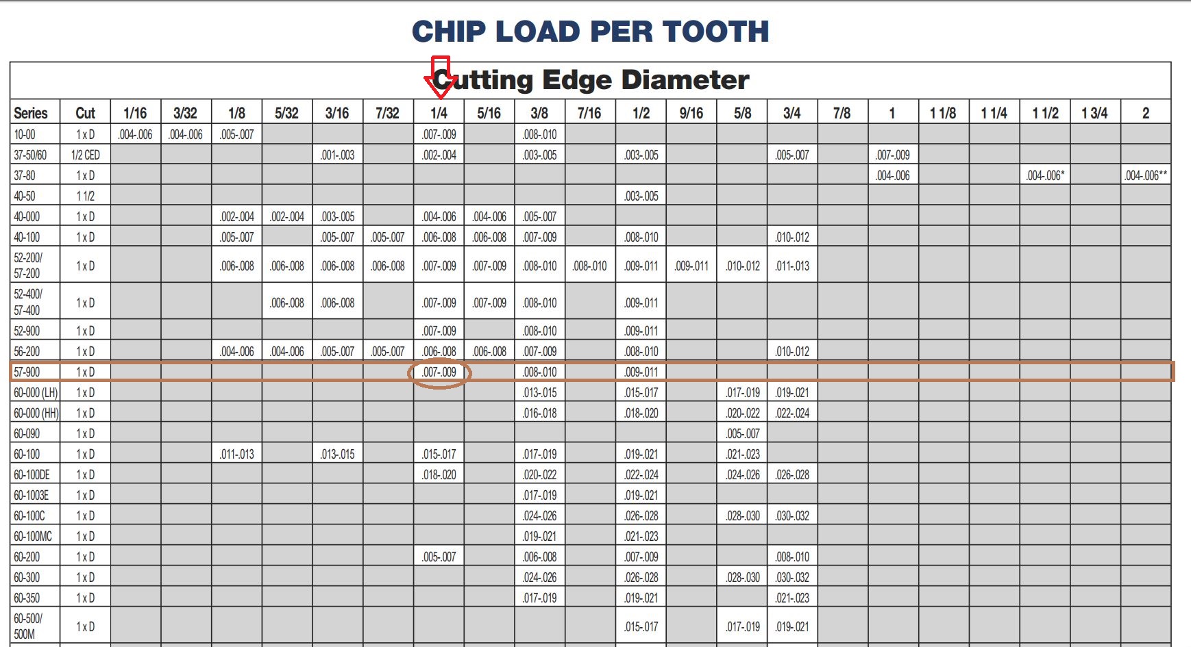
So having the Spindle set at 12000 rpm , number of cutting edges at 2 , and chipload at 0.008'':
Feed Rate = 12000 x 2 x 0.008 = 192 inch/min = 81 mm/sec
From previous test we know that feed rate is too much for our machine ( the cut scream very bad ) so I used 80 inch/min with a pass depth of 3mm ( total of 7 passes to cut through all the 18.4mm I setted in Aspire.Explained later ).
Aspire
I created the cutting files for the shopbot whit Vectric Aspire.Once I exported the DXF file from solidWorks is important to close every closed contour,because Solidworks export them as lines.
To do this I used Illustrator :
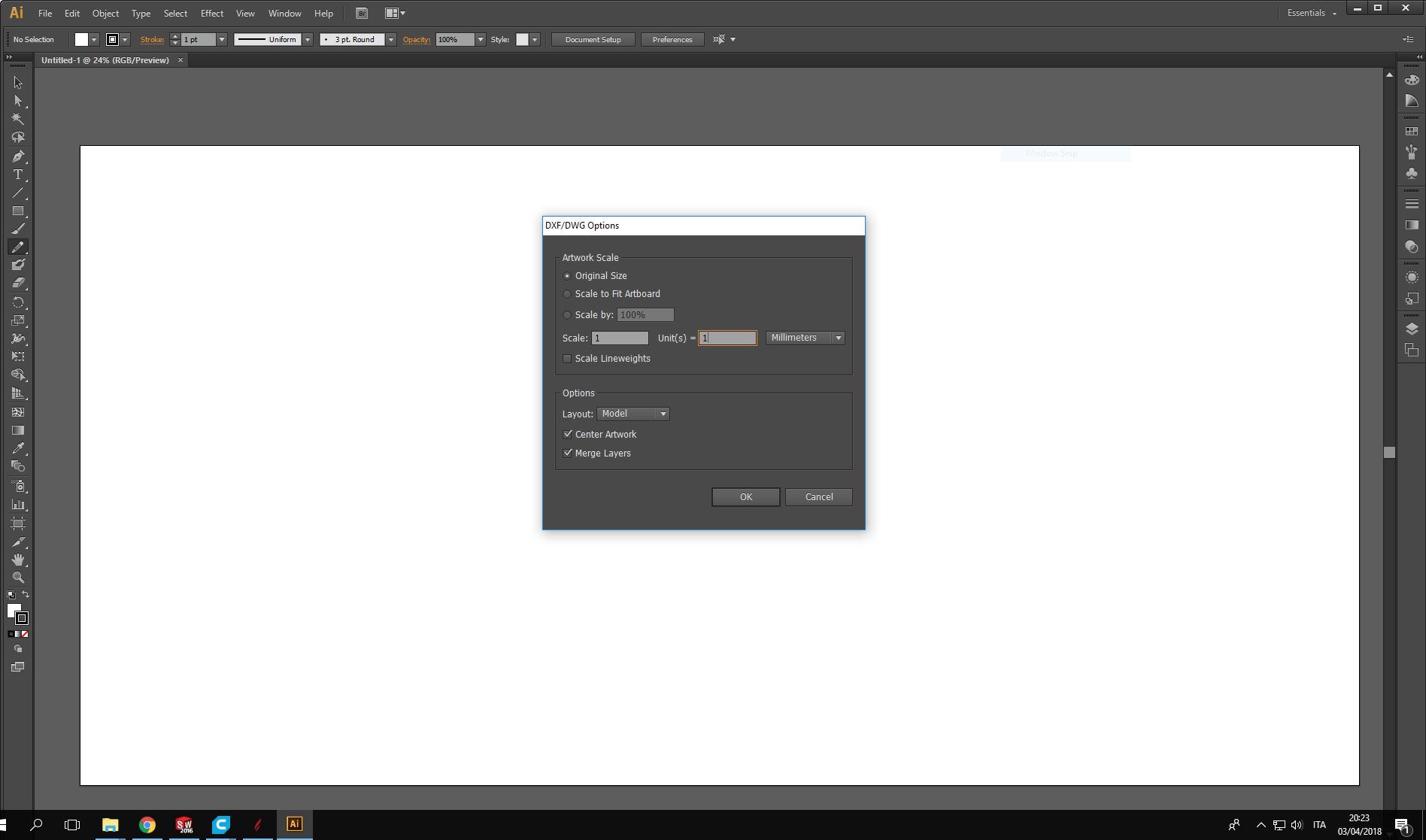
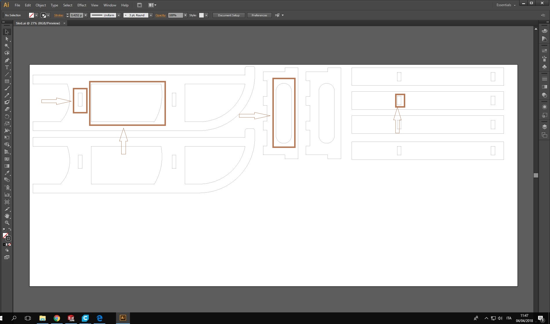
I selected every closed contour (like those I highlighted in the image below) and typed ctrl+j
Here comes Aspire.
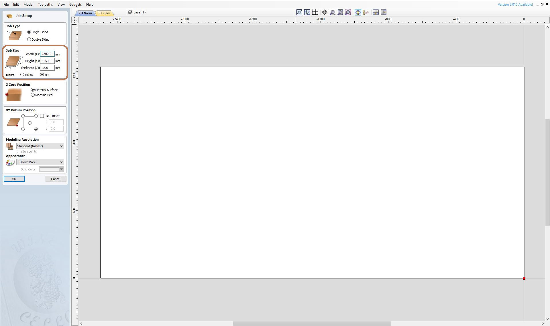
First of all I created a new file and I setted the Job Size as the dimension of the OSB plank I had,so,once I uploaded my dxf file of the sled,I could see if the plank could fit all the pieces.
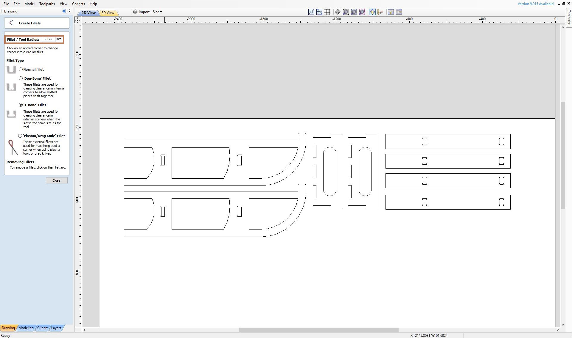
Once I opened my dxf file I created the T-bone fillet using the Create fillet feature.Here is important to set the right tool radius so the machine will make it in a single pass.The importance of the T-bone is that the CNC machine could not mill a perfect right angle from the inside.The holes for the joints ,that are rectangular,would not fit the joints, that are milled whit an external cut (so the CNC machine could mill a perfect right angle ).
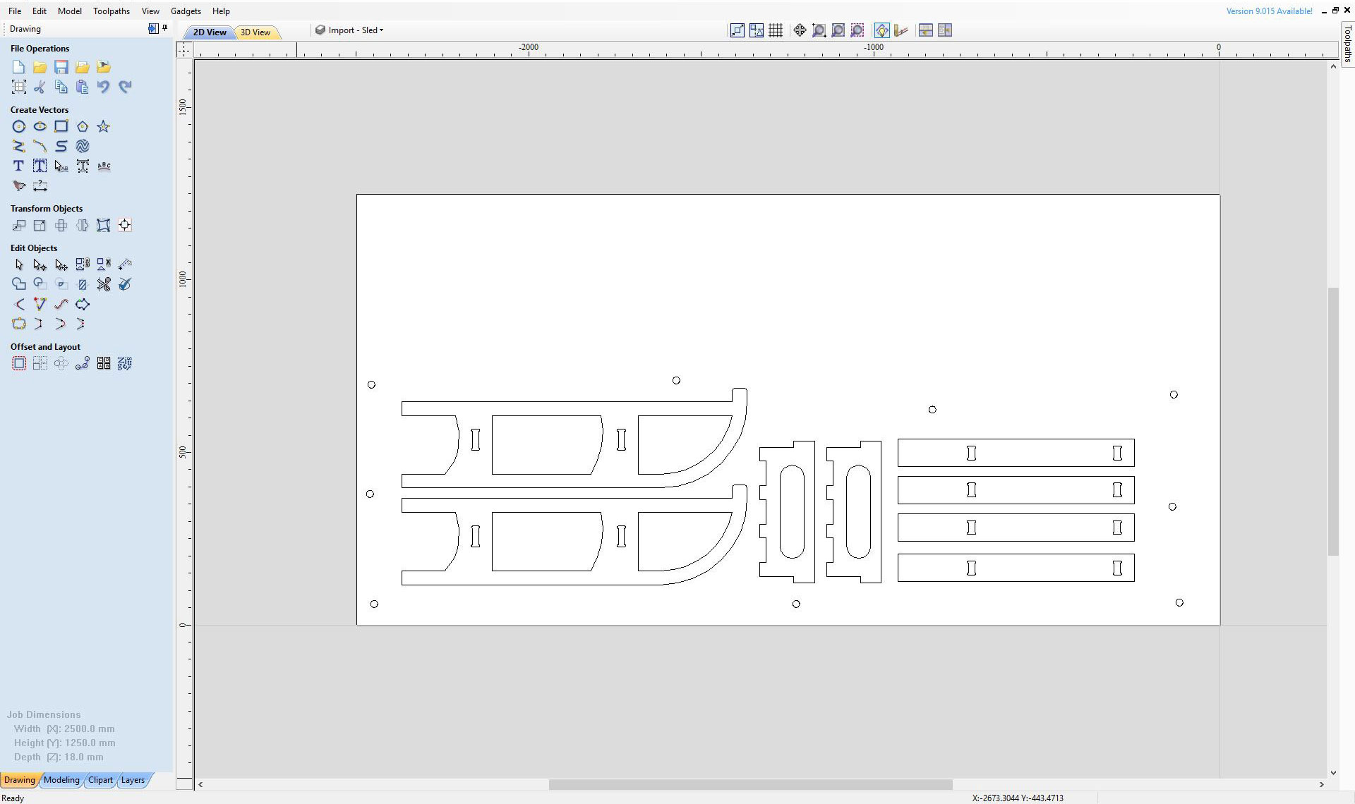
Next I positionated the pieces as I wanted
Those small circles would have been 2mm pocket toolpath to mark the spots where I would had applied the screws but I didn't use them and I followed the advise of Flavio and I applied the screws at each corner of the plank.
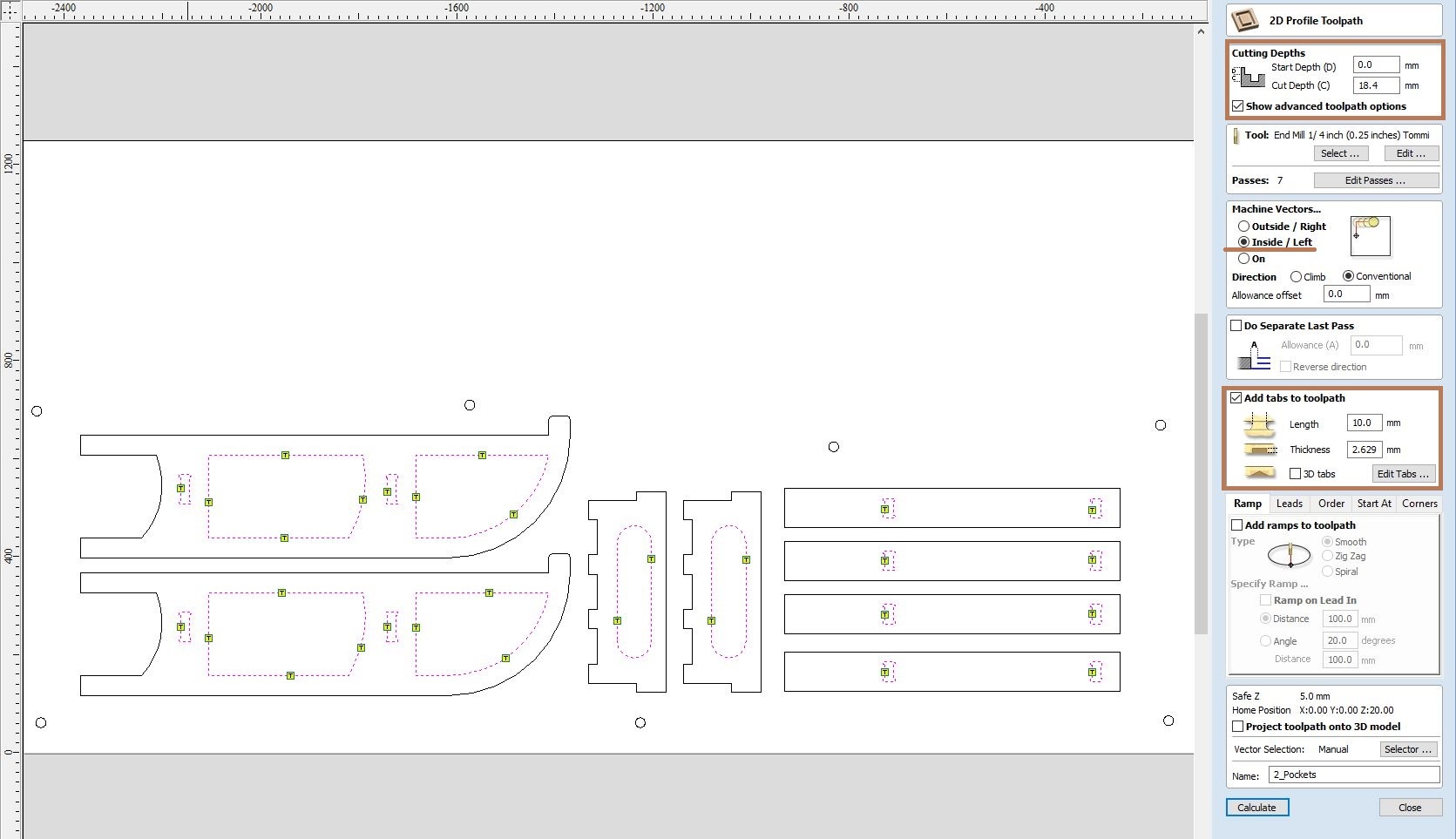
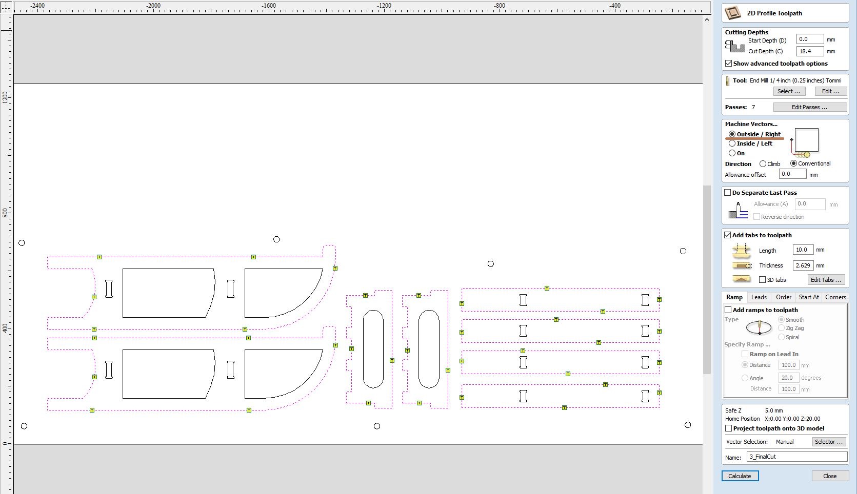
Then I created the first toolpath.As you can see I setted the Cut Depth to 18.4mm instead of 18mm ( the real thickness of the osb) to be sure that the cut would be through all the plank.
I added a reasonable number of tabs to be sure that the small pieces were not launched at great speed around the room.
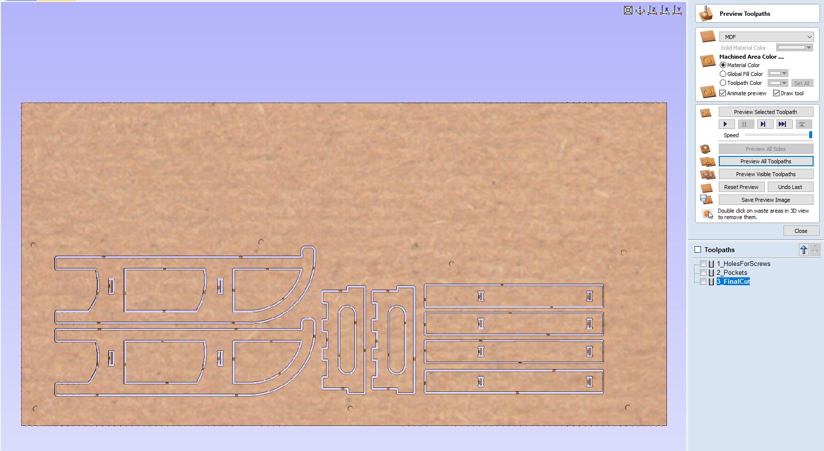
The second toolpath :
And I checked in the preview section if everything were allright.
The Cut
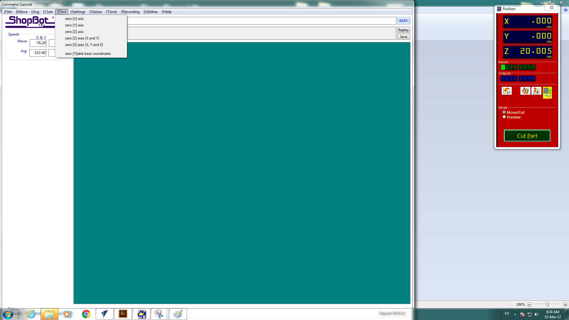
Once I created the toolpaths we had to get the machine ready. The first thing was to clean the sacrificial bed from the remains of previous cuts.Next we opened Sb3 -Shopbot software and we started a warm up routine to get the spindle ready.(photo tooked from Silvia)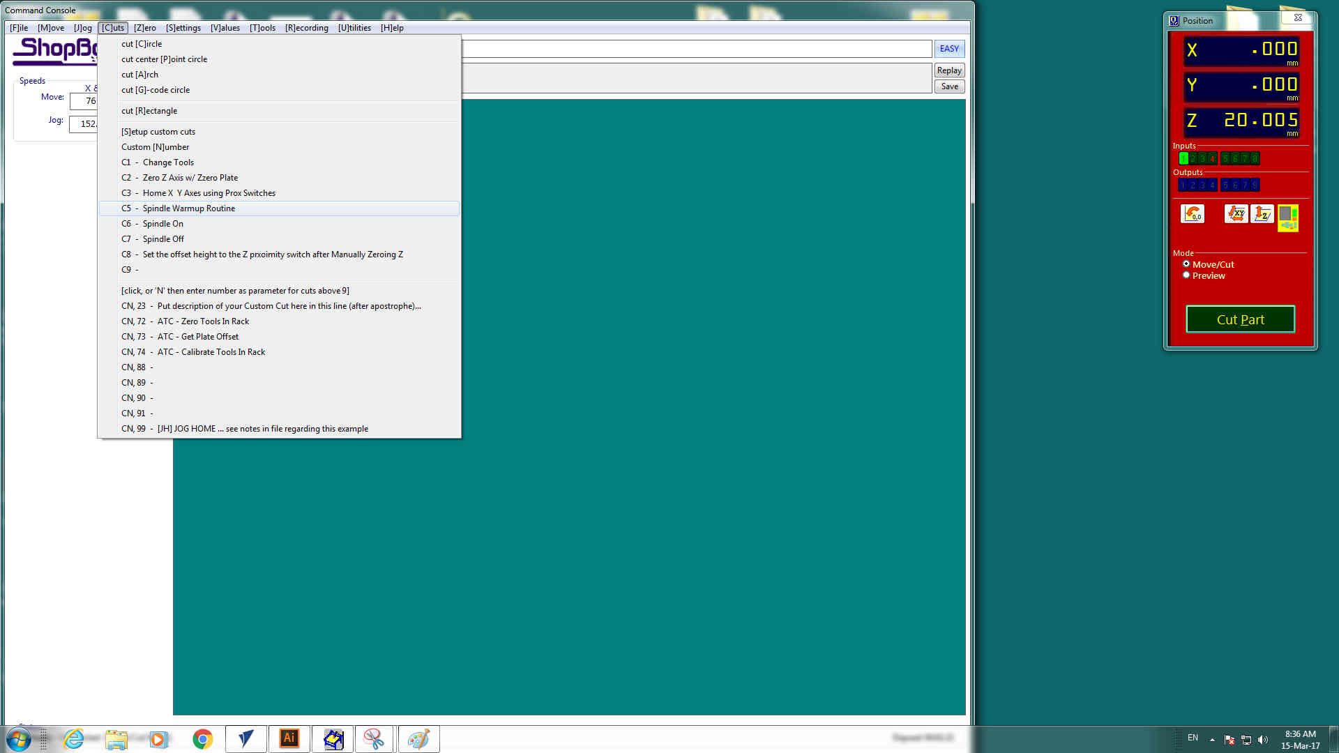
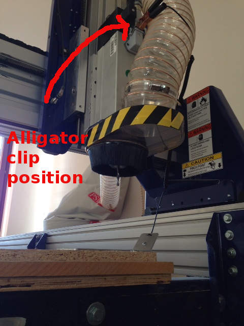
Next I inserted the 1/4 end mill into the collet and tighten it up. After we used the Z zero probing plate to set the machine zero of the Z axis(photo tooked from Silvia)
We manually(via software) moved the head to the origin of the X and Y axis we wanted and go through Zero--> zero [X (or Y)] axis (photo tooked from Silvia)
Then we uploaded the toolpath files and whit the stop button in our hand we started the milling process
Work in progress :
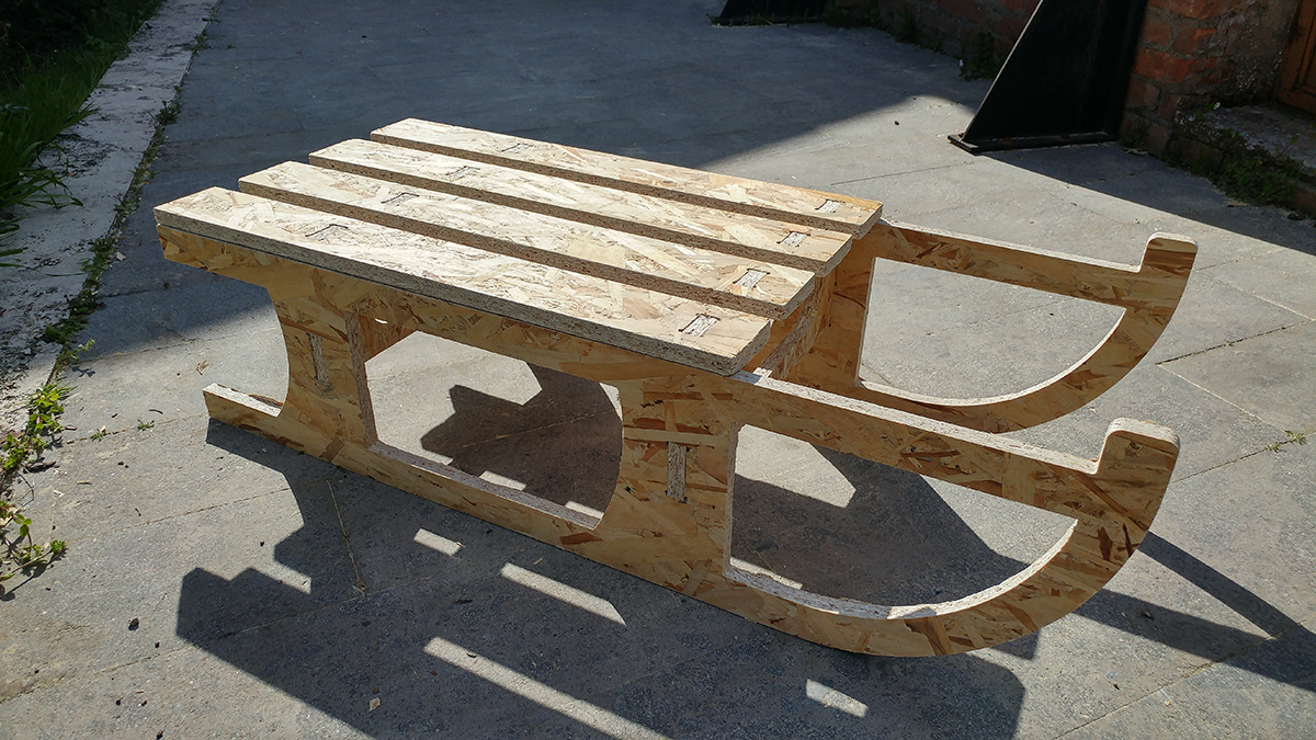
Before starting to assemble the sled I used the sandpaper to make all edges smooth.
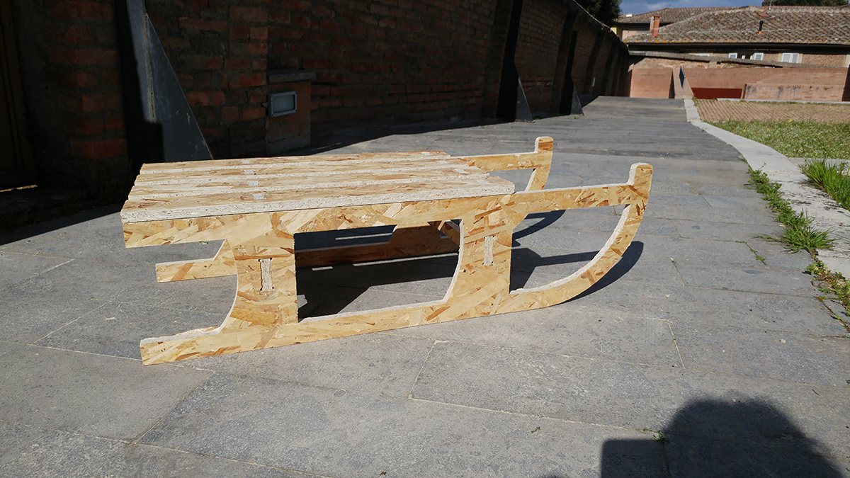
Hero Shots: