
Things to do :
- Measure something: add a sensor to a microcontroller board that you have designed and read it.
Designing the board
For this week assignment I wanted to use two sensor that probably I will use for my final project: the sonar and the IR sensor. I designed the board in a way that could handle both sensors.I provided it whit two couple of pinheaders for the power supply(the IR sensor had two components that needs to be supplyed),and another couple of pinheaders for the two remaining pins of the ATtiny45.First of all I open Eagle and I started designing whit the datasheets of the ATtiny45 and the sensors open by my side.
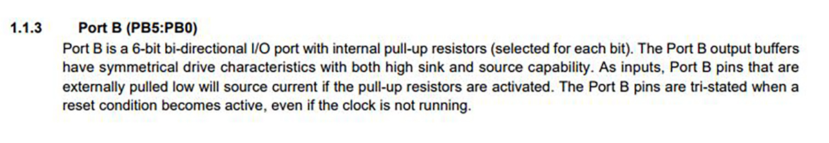
Reading this part I understood that I would need a 10kOhm pull-up resistor,but ...
The Ports of the ATtiny45 provide one already.
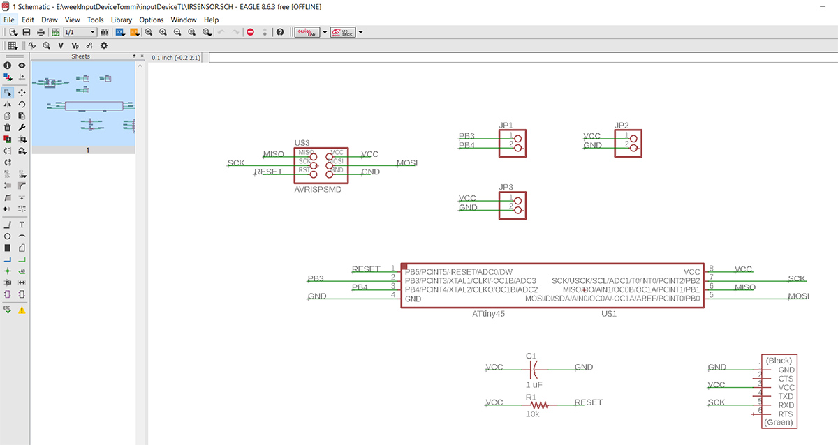
Once I knew all the components I had to solder in my board I started designing the schematic. I didn't remember much about Eagle so I read once again this tutorial. I tried to be as tidy as possible helped by the fact that I had to manage only a few components.
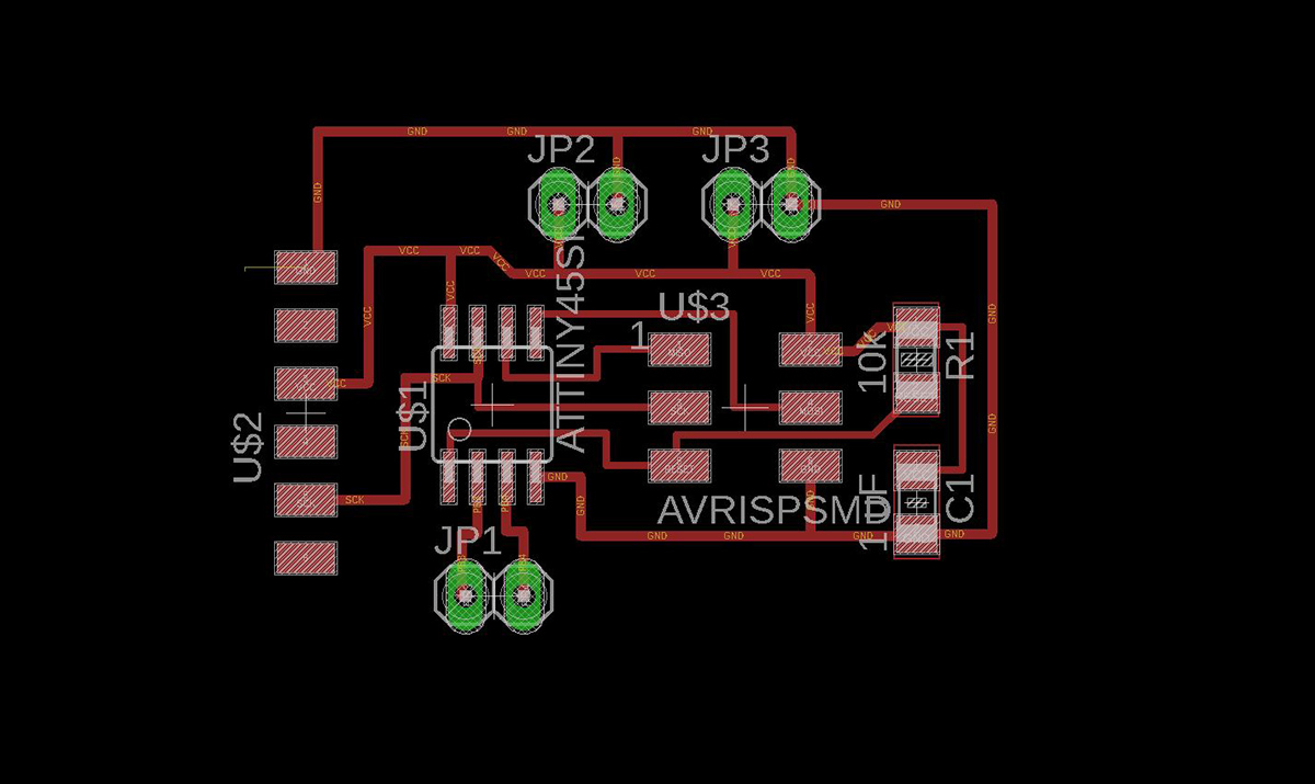
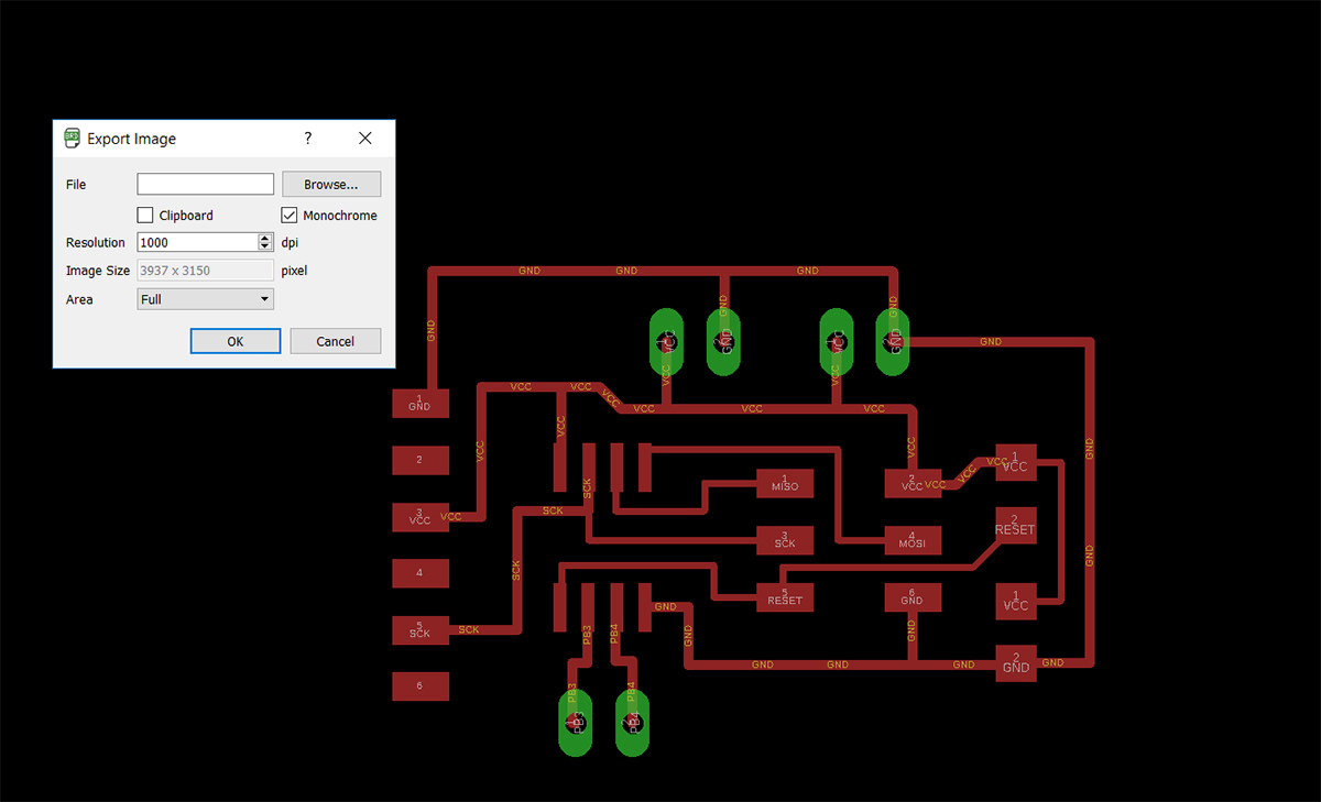
As I did during Electronic's design week, I used Gimp in order to adjust the size and to create png for the milling file.
Remember to export this way :
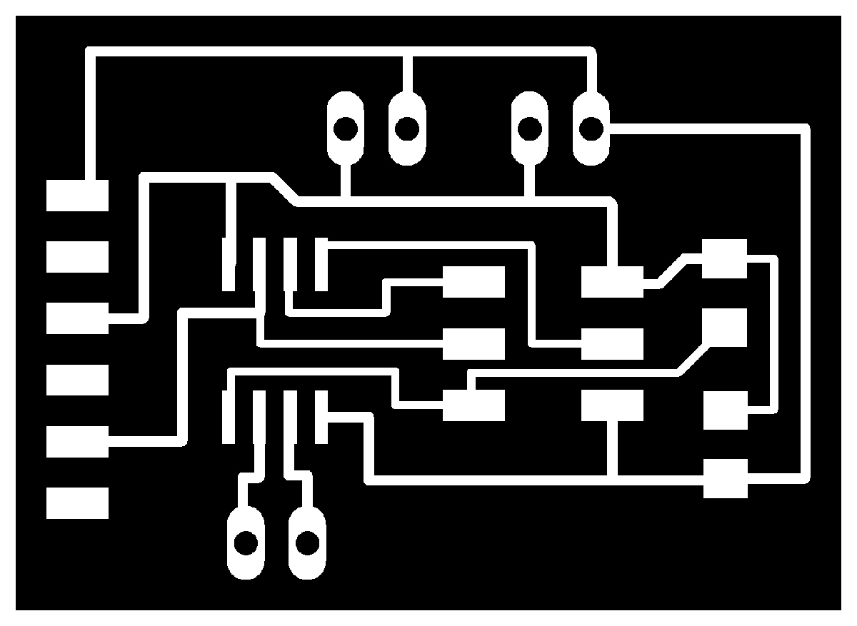
Those are the file.png :


The Milling process went well and I proceeded to solder every component.
BOM :
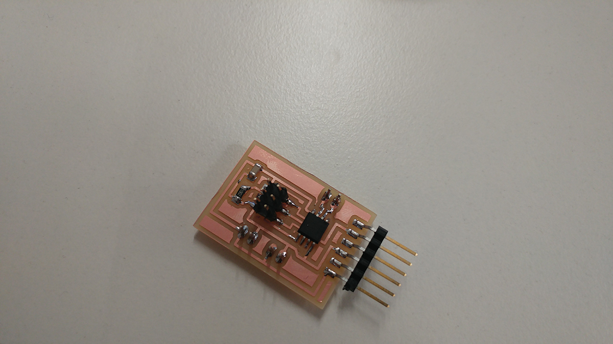
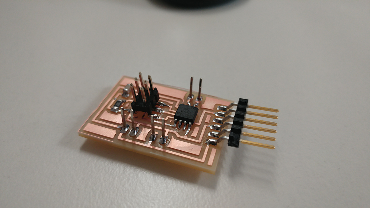
I checked with the multimeter the connections, everything looked ok, so I went for the programming part.
Coding
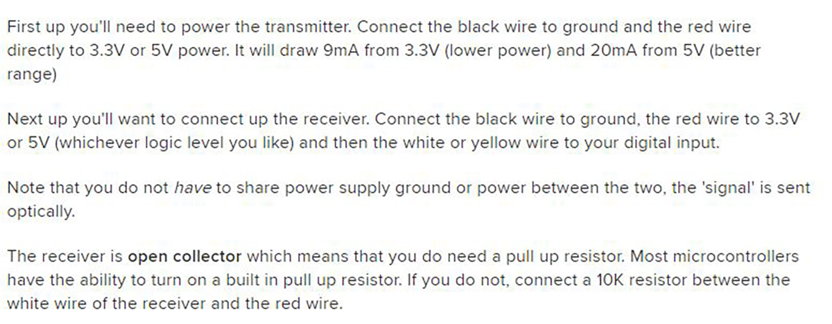
IR sensor
I started whit the IR sensor.It is composed by 2 part : The Transmitter and the Receiver.The receiver send a 1 to the microcontroller if it recognize IR light and a 0 if it doesn't.I wrote a few line of code whit Arduino IDE that make the board recognize a black surface (The black color doesn't reflect light so the receiver should send a 0).
Note :Remember to activate the internal pull-up resistor.
Sonar
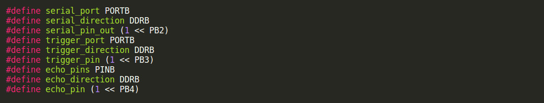
(Hold the left button on the image to zoom in)Then I tried to connect a sonar module to my board.Once I hooked everything up I modified the supplied code(link for the code) as shown in the image below.
I flashed the program in the microcontroller using the AVRDude toolchain and I checked if it worked.
I downloaded the .py file from fabacademy's page, tried to start the python program, but it didn't work. That was because I didn't install a program called "python-tk"

Simple solution :

I proceeded to test if everything was ok, and it was!
