The developing process started whit the production of the turbines.
Equipment
Everything was printed whit an Ultimaker 3 charged whit this PLA filamet.To make the turbines spin I had to use ball bearing.Those are the ones I used (dimensions 22 x 8 x 7)
Design
I used SolidWorks for that,but before I started to draw anything I created a txt file called equation.txt where I defined all the parameters I was going to useAs always,Hold the left button on the images to zoom in
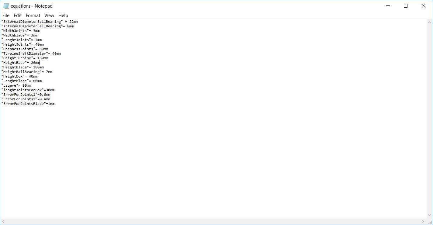
The syntax SolidWorks require is ,as shown in the image,
"NameOfTheVariable"=values (optionally the unit of measure,if not written it will take the default one)
Next,whenever I created a new file,I imported this equation.txt file : Tools--->Equation--->Import--->Equation.txt
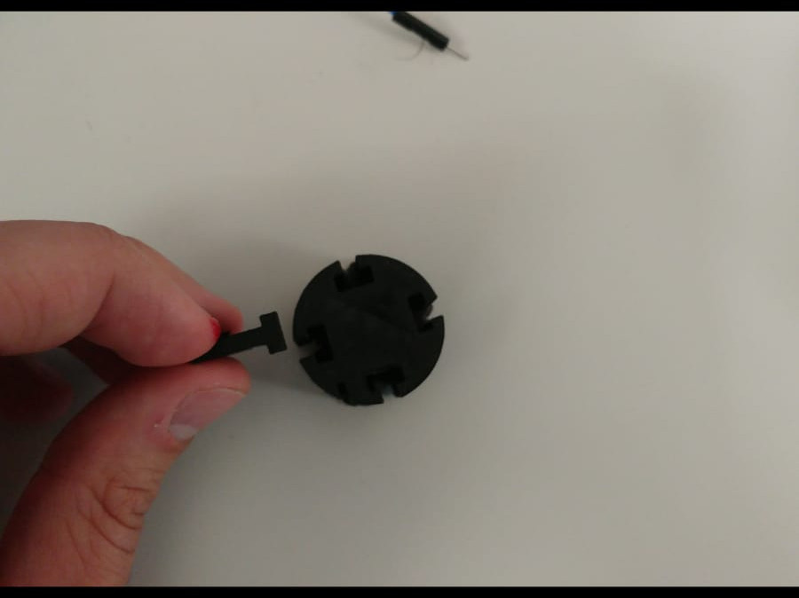
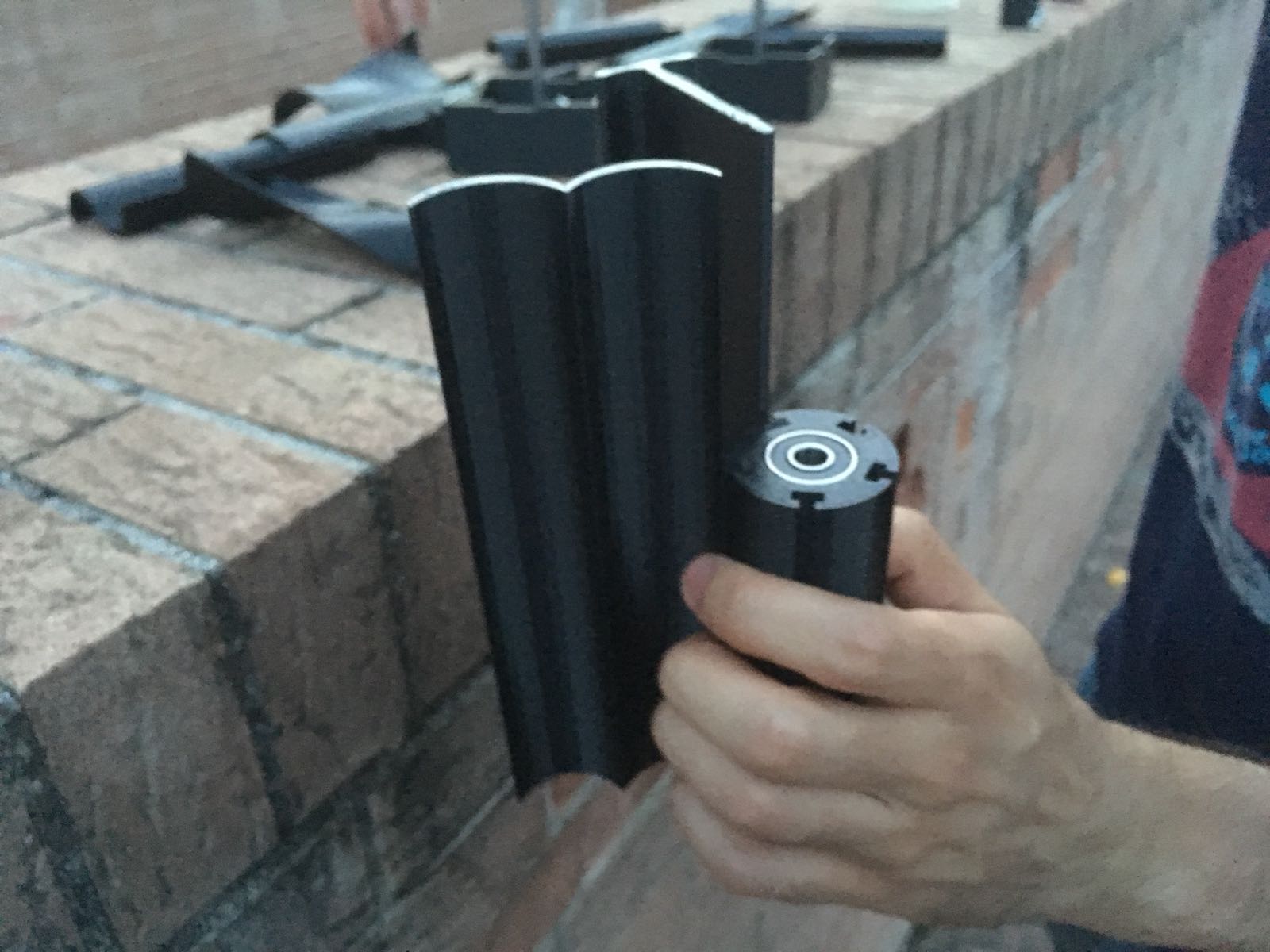
First of all I had to decide the joints for the blades.I had to answer to this question how will the blades be attached to the shaft of the turbine?
I choosed to use a T shaped joints so I started with some test to find the best settings for the Ultimaker 3 in order to make the fit to be perfect.
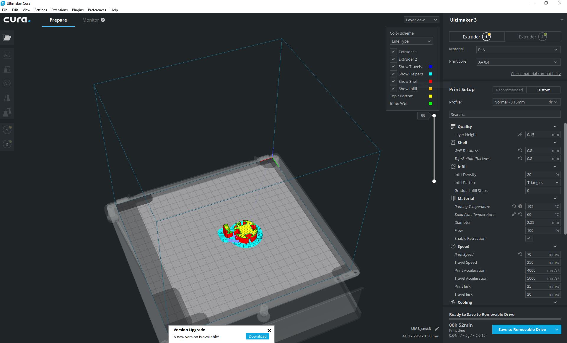
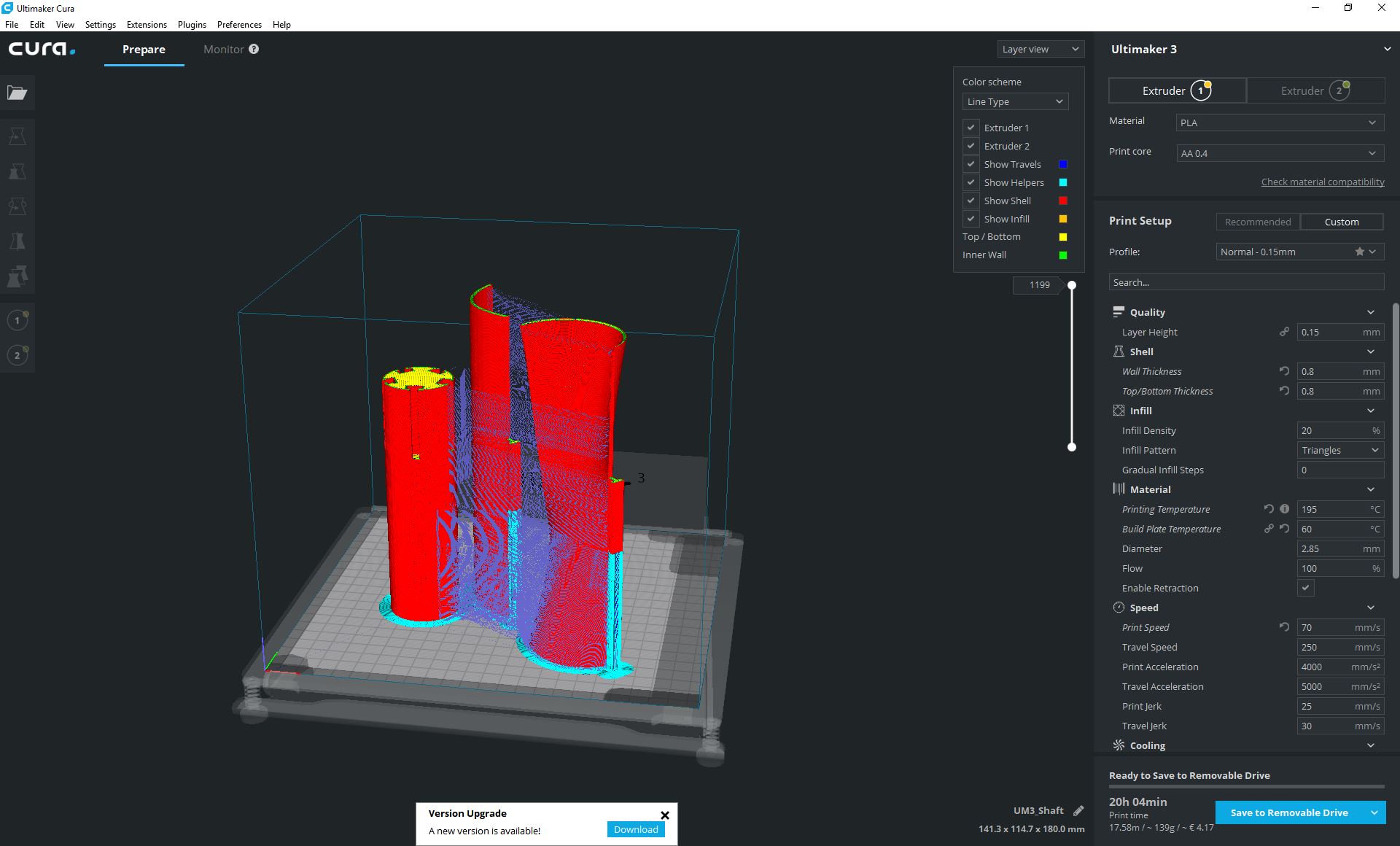
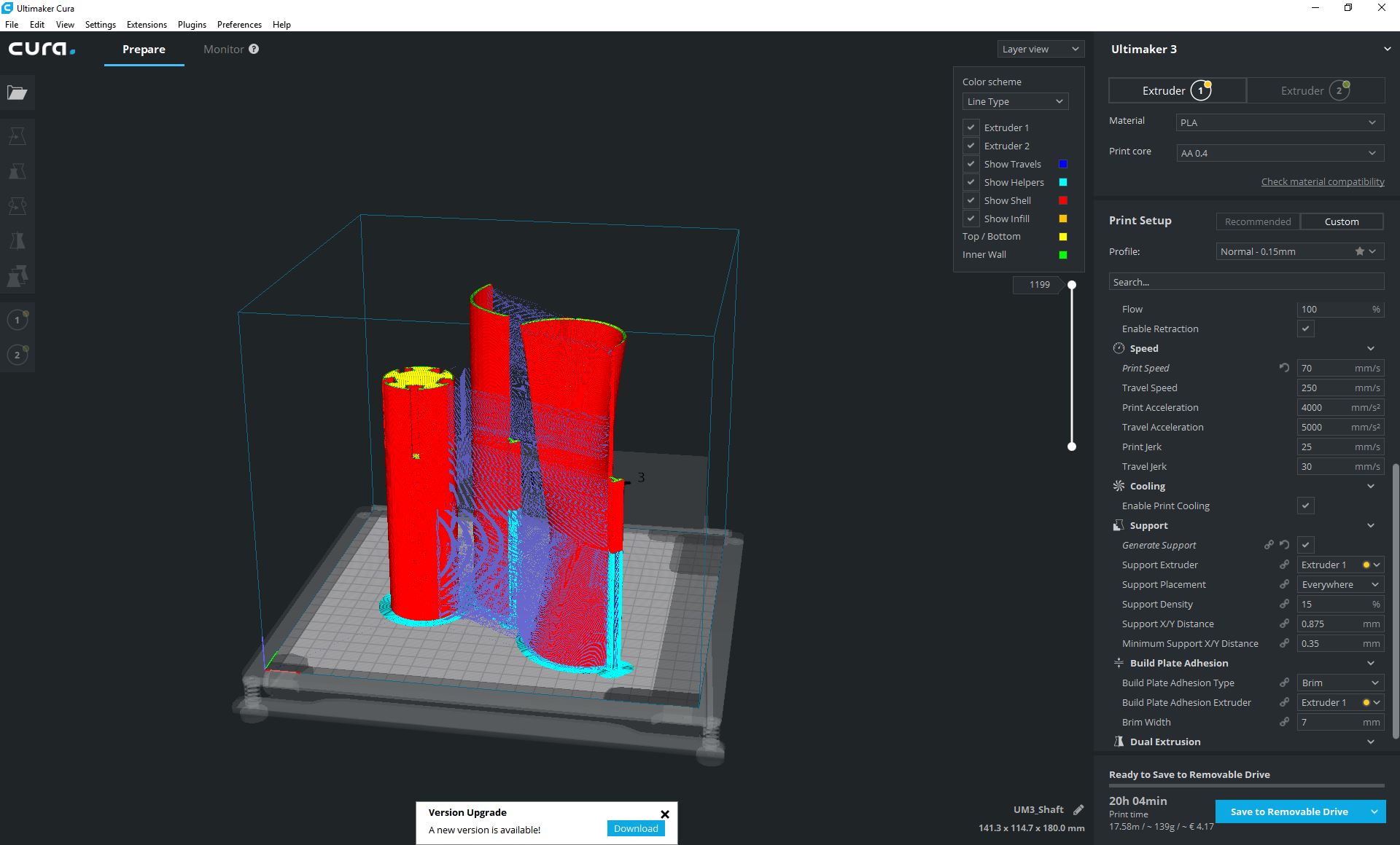
The settings that result to be the best for me where the ones shown in the 2 images below.In particular the settings that matter the most are :
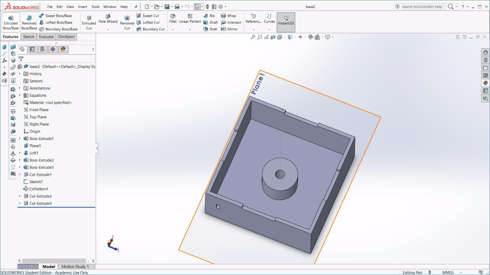
The first piece designed was the base.This is the first prototype but the inner shaft printed in PLA lacked of hardiness
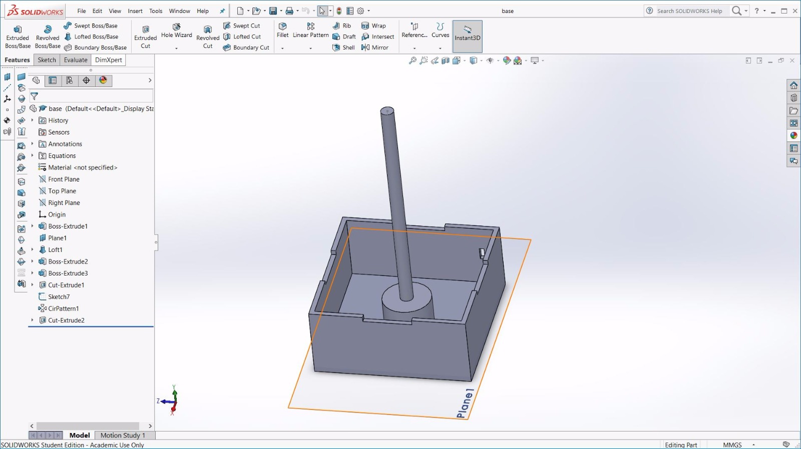
So I provided the base whit a hole (diameter 8.4mm) in order to fit a steel bar (8mm diameter) that we had in our lab.That was the best choice both for reason of hardiness and for make the ballbearing I was going to use to not yoke.
That was the design of the cover that I lasercutted to save time.Fortunately I found in our lab a 3mm thick plywood that was perfect for my purpose.
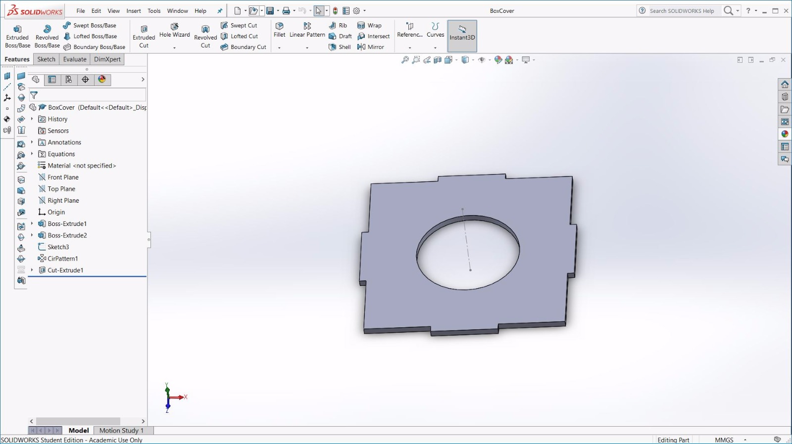
When I laser cutted the cover I didn't consider the kerf due to the fact that also the 3d printing has some imprecision,so the 2 errors of the 2 process should had balance each other.
This are the settings I used for my Laser cutter :
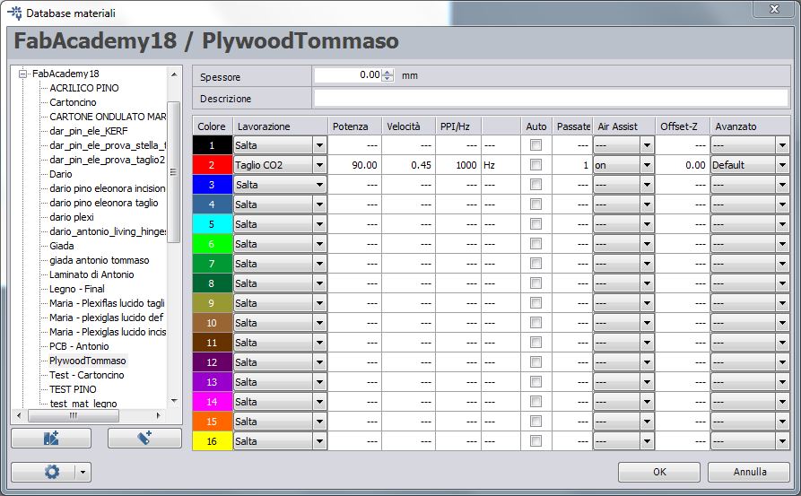
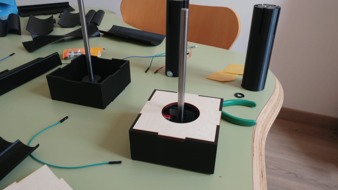
And it actually worked,the assembly was perfect.
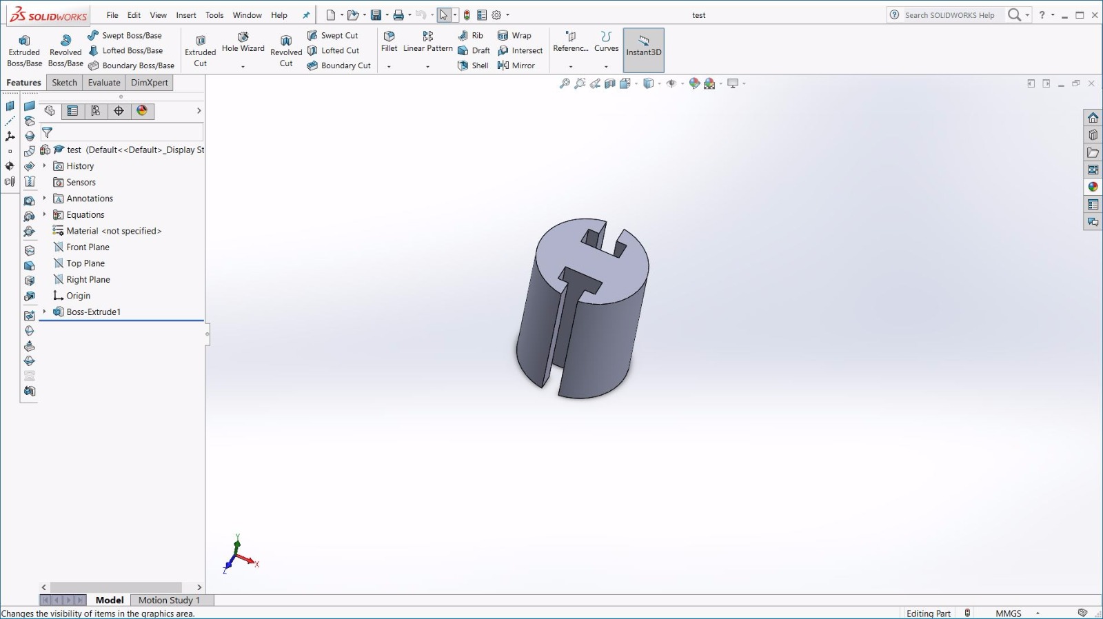
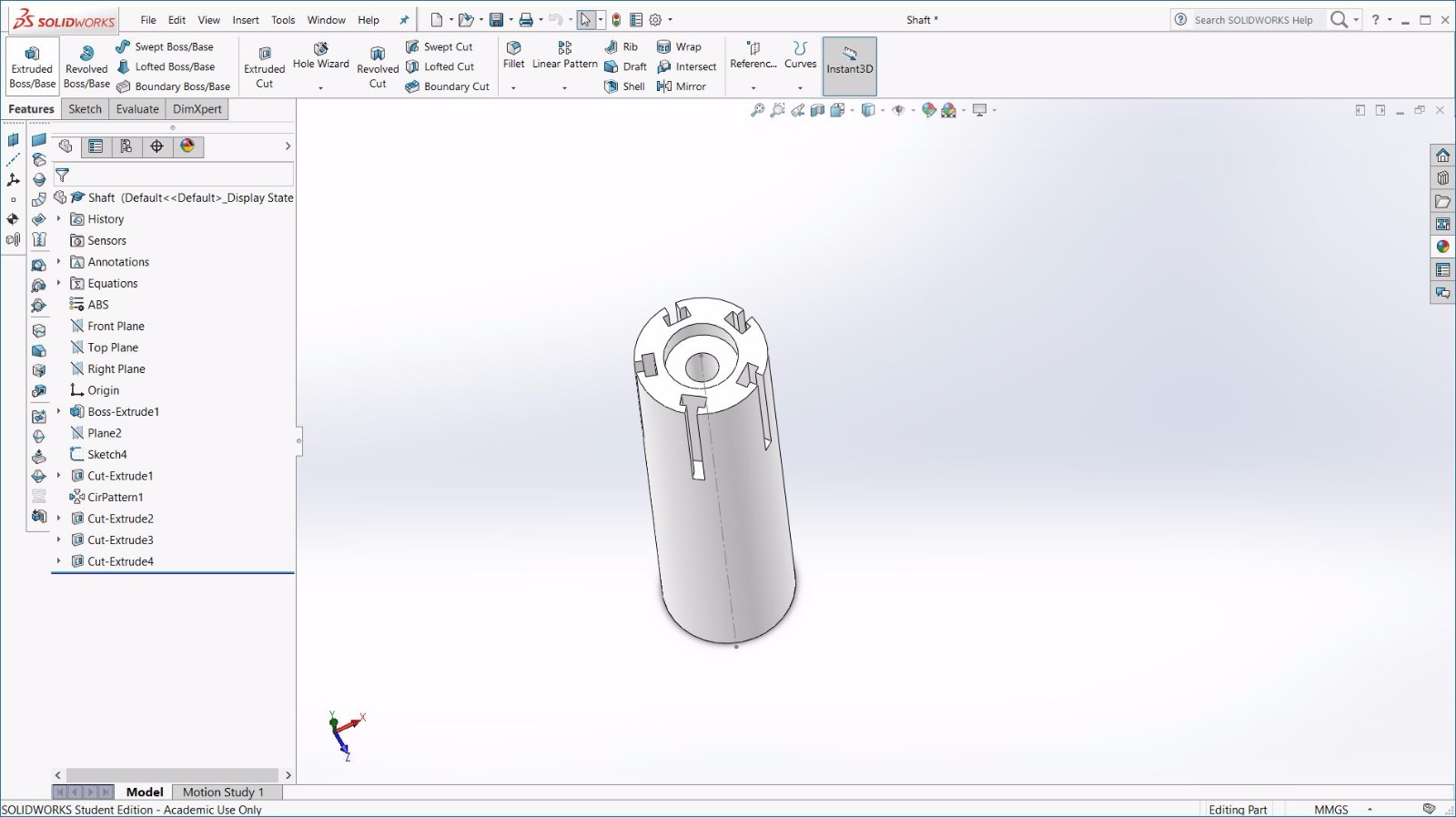
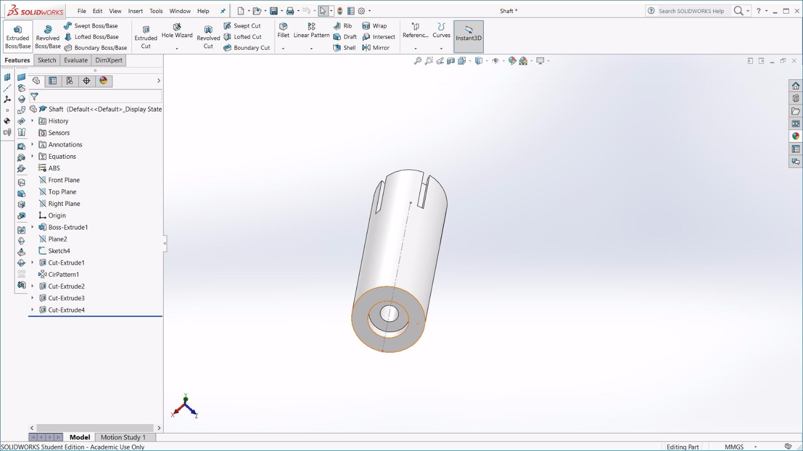
Then it comes the shaft.This is the design I made,providing slots for ballbearings on the top and at bottom of the shaft.I designed only one T-shaped holes for the joints on the top (height of the extrusion cut = "heightJoints") and then I used the circular pattern choosing to make 5 instances of the feature.
I planned to print other shaft whit less (or more) holes for joints to give the kids the possibility to choose how many blade they want to use.
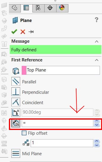
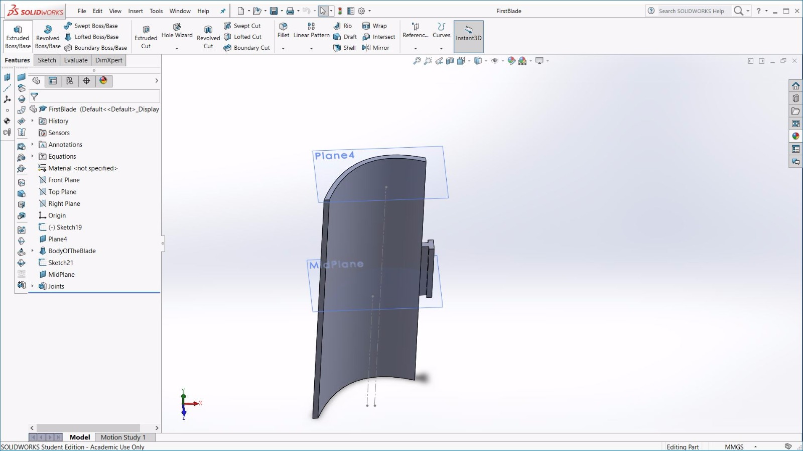
Moving on the blades I found a sort of bug in my solidworks,googling on the internet it seems that i'm not the only unlucky one that had this problem.I wanted to create a new plane parallel to the top plane but spaced by a parameters that i previously defined as shown in the image below:In the message box highlighted I wanted to write a dimension defined in my equation.txt file,but it was not possible.
The solution I used was to create a new sketch in a plane perpendicular to the top plane,draw a "for construction" line long as I wanted
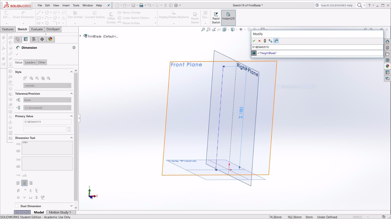
Then the new plane had to pass through the endpoint of the line I defined in the previous scketch and had to be parallel to the top plane .
With this technique I defined all the planes i needed to use.
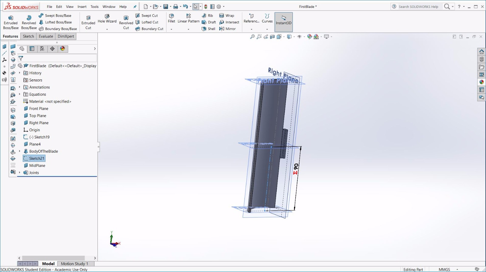
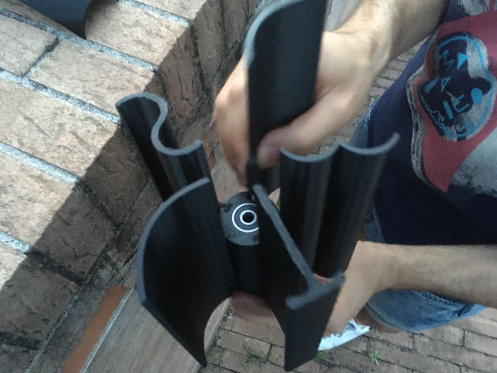
The joint has to be in the perfect middle of the blade,so the blade could be fitted in both ways.
Once I designed 5/6 shapes of blade I made the assemble to check if a possible combination of them could be nice to see for a kids
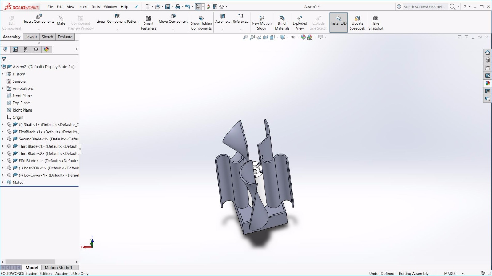
Those are the 3d model of the blade I designed :
The setting I used whit CURA to create the gcode for the Ultimaker3 are the ones I listed above where I was talking about the test,however those are the same setting I used for the printing of the blades ( and the shaft):
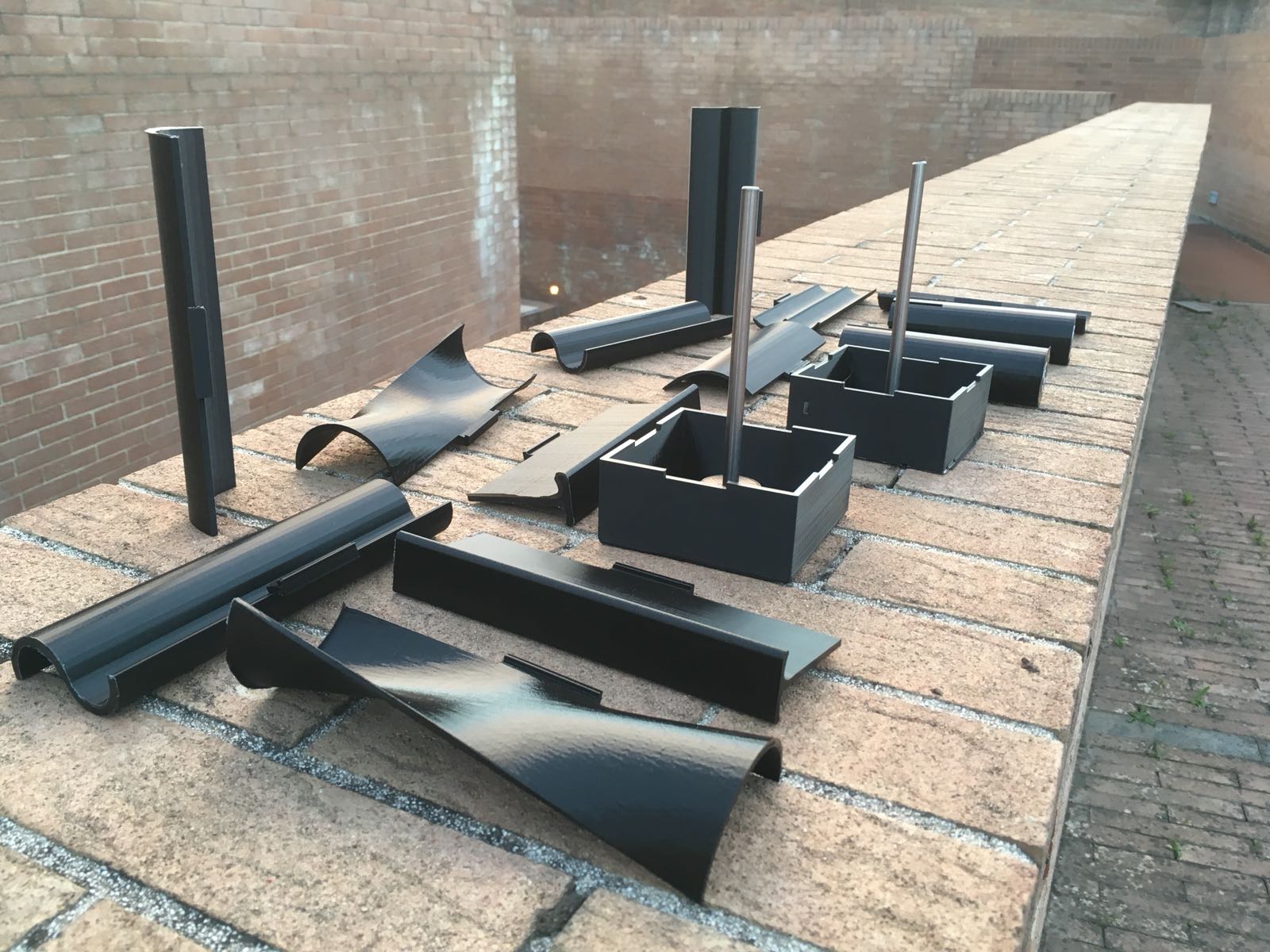
And after some days of printing I had something to work with:
The House
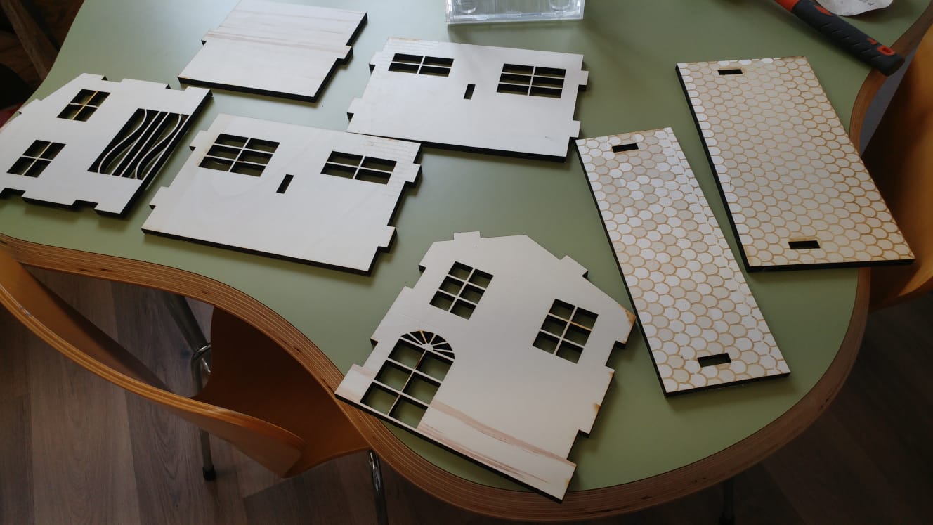
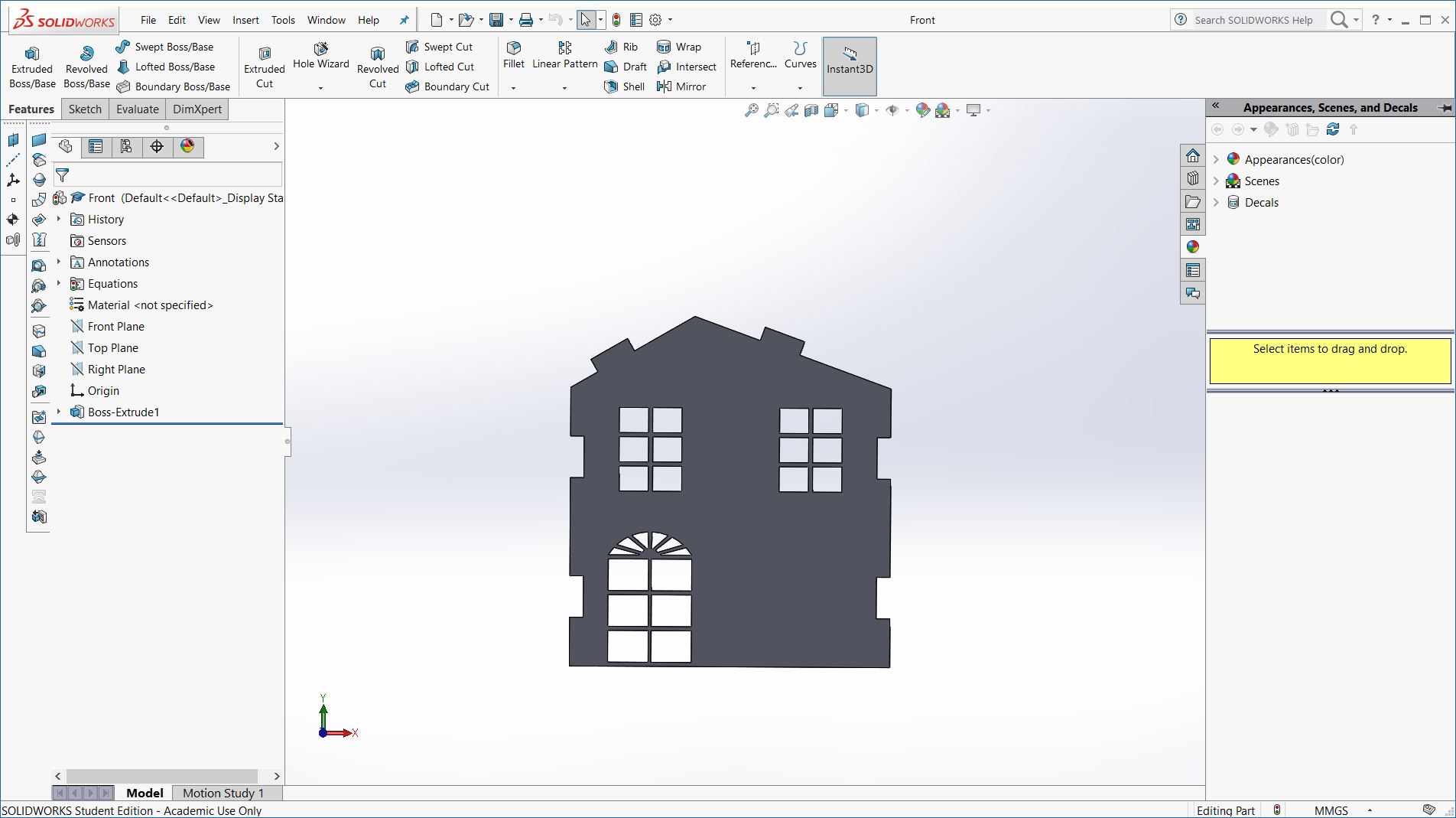
As always I created a txt file called equation.txt where I defined all the parameters I was going to use,next I moved on designing the House.It is composed by the front,the back, and 2 side parts.The material I had for the House was a 10mm thick plywood.
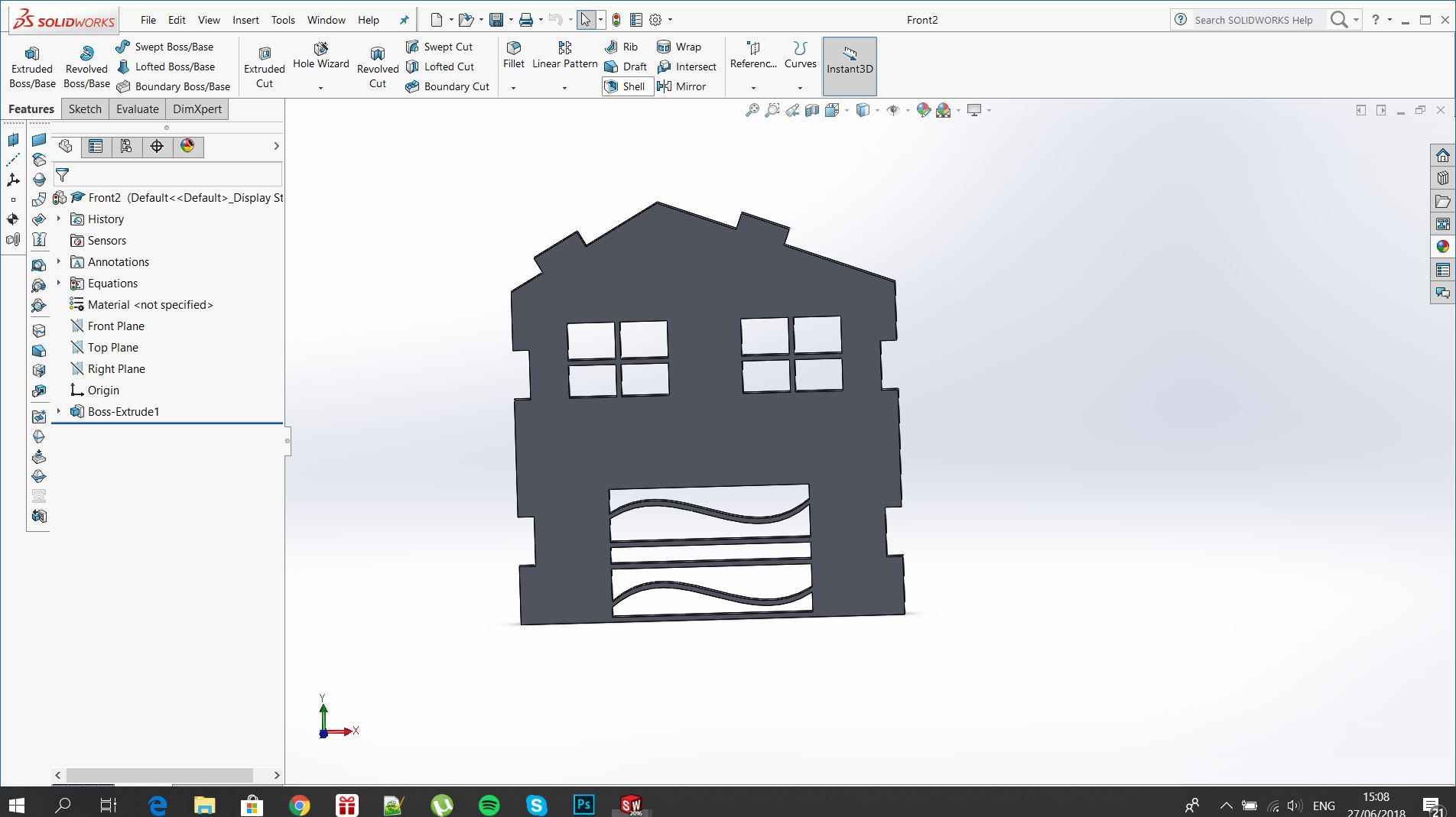
The Front
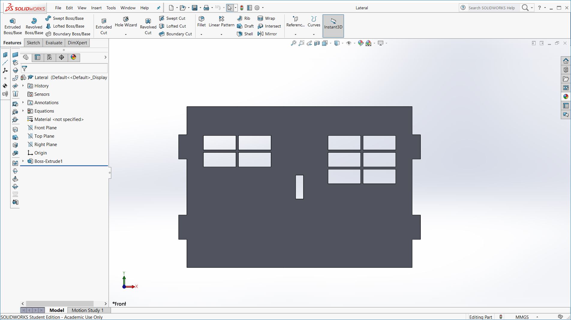
The Side part
The Back
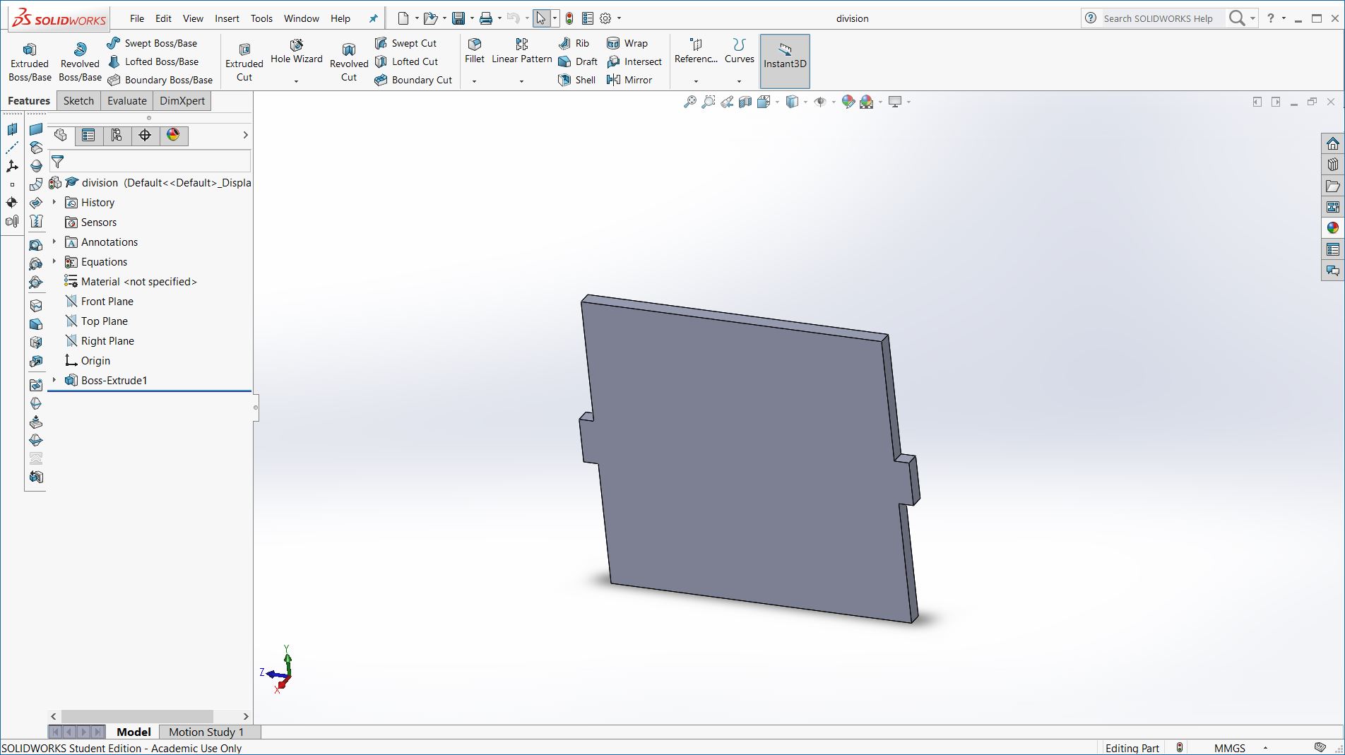
And a piece to be joined in the middle of the house to make the structure stronger :
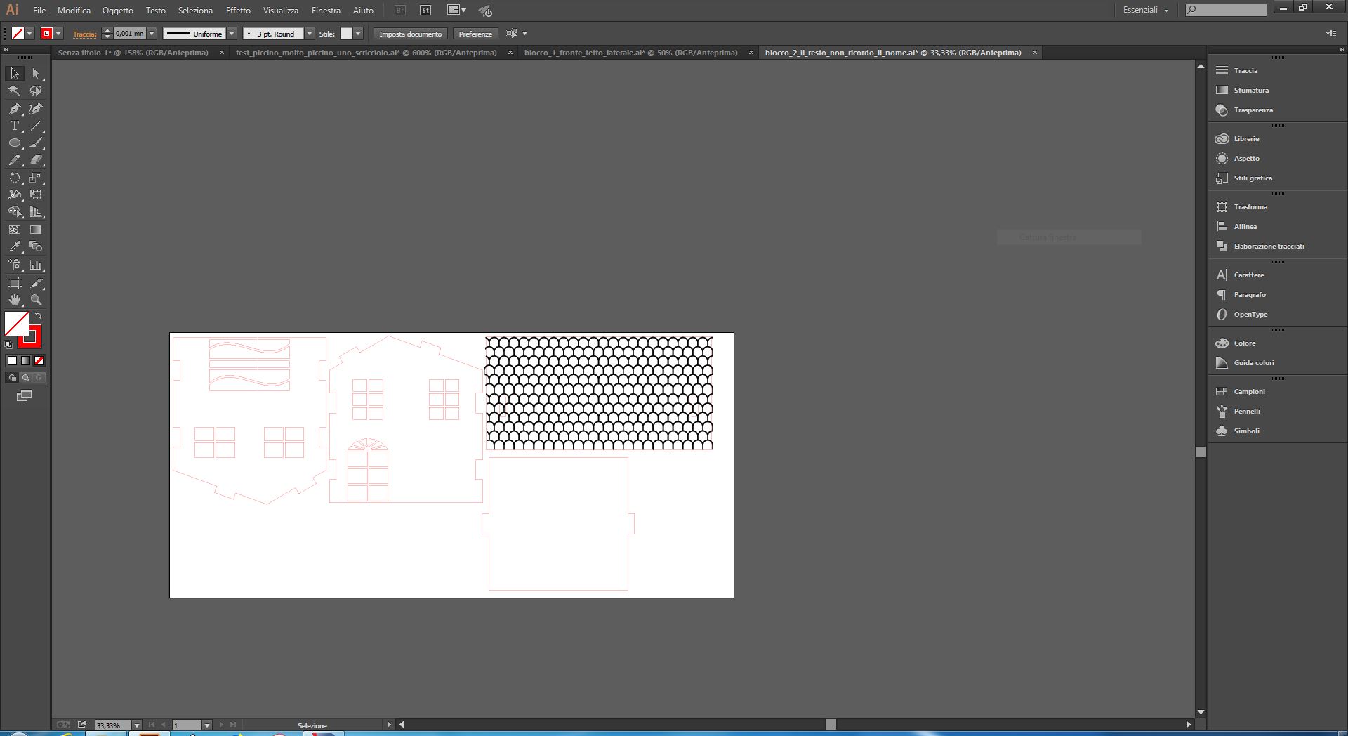
Once I made the assemble to check if everything was fine I exported all the files in DXF (Like I did for the Computer-Controlled Cutting week) and I moved on Illustrator in order to create the cutting file.
I google for some svg file rapresenting roof tiles and I found this file.
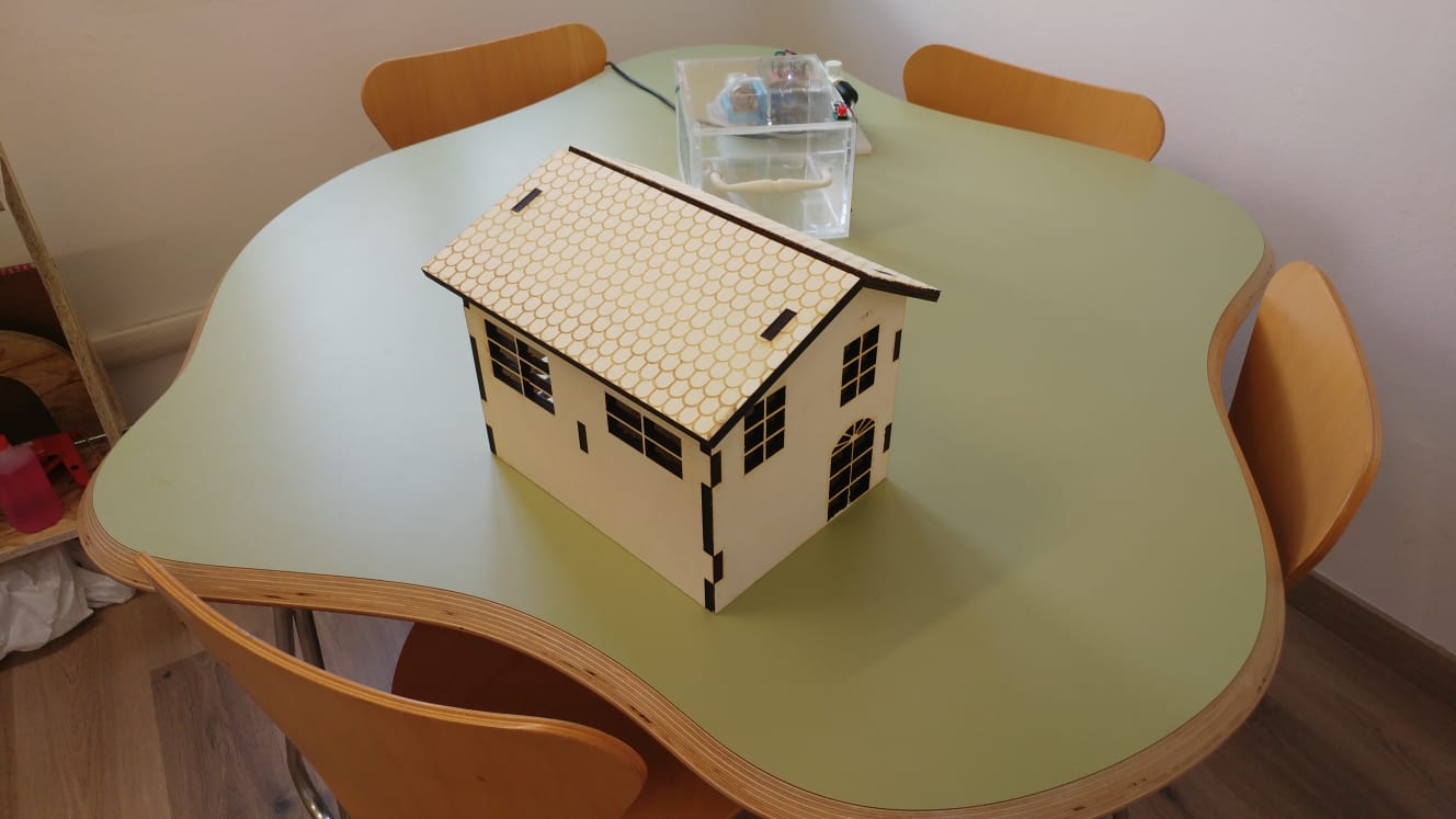
I downloaded it copied and pasted on the roof in order to engrave the roof tiles in the wood and craate a nice looking house.
The settings I used were the ones I highlighted in the images below (remember,material used : 10mm thick plywood)
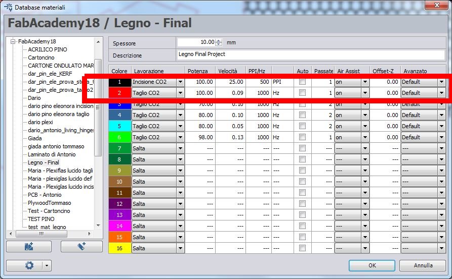
I covered the plywood whit paper tape to pretect it from burned wooden dust
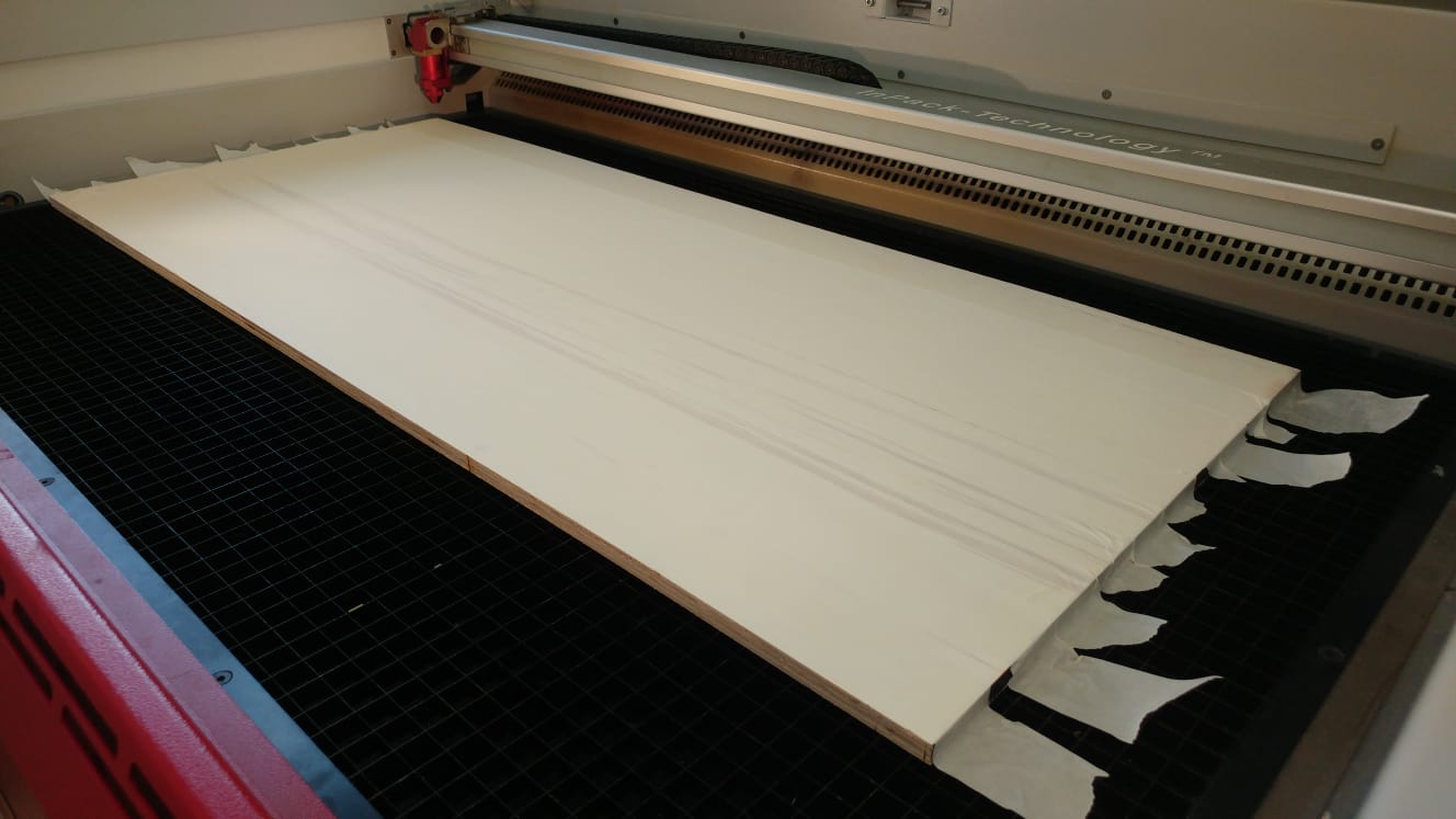
The settings were good,the cut was fine and i had to use the sand paper in just 2 or 3 edge.