I started the programming process whit the code that would count the RPM of each turbine.
I provided my board with this HallSensor and i attached a magnet to the shaft of the turbines
To understand how the hall sensor works I wrote this simple code.It does nothing else than read the values of the sensor and print it via serial.
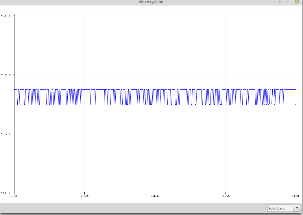
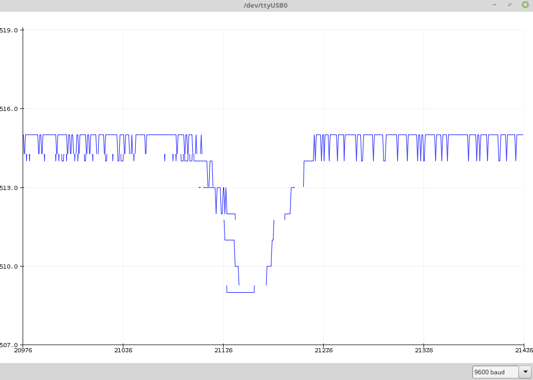
Next I opened the Arduino plotter to see his behavior


As you can see in the image the lecture of the output of the sensor is stable when it doesn't recognize any magnetic field.The microcontroller,that has the output of the sensor linked to a 10-bit analog to digital converter,map the voltages between 0 and 5 volts into integer values between 0 and 1023 thanks to the AnalogRead().In a rest condition the output voltage of the sensor is about 2.5V ,the half of the alimentation voltage.
Looking at the plotter I decided which values will activate the counter to increment.It drops when a south pole is approaching.In my case considering the distance from the board and the turbines I thought that 510 should had been fine.
That was the code for the board that I made in the Networking and communication week.To send this values I used the Bluetooth that I learned to use in the same week.
The only thing to change are those line of code,replacing
whit this :
Based on the RPM it choose the pattern of lights: from soft colors and low brightness,to strong colors and high brightness.To choose the color I used this "web palette".It gave me the opportunity to know the RGB code once I choose the color from the palette.
I provided my board with this HallSensor and i attached a magnet to the shaft of the turbines
HallSensor
How it works :To understand how the hall sensor works I wrote this simple code.It does nothing else than read the values of the sensor and print it via serial.
Next I opened the Arduino plotter to see his behavior


As you can see in the image the lecture of the output of the sensor is stable when it doesn't recognize any magnetic field.The microcontroller,that has the output of the sensor linked to a 10-bit analog to digital converter,map the voltages between 0 and 5 volts into integer values between 0 and 1023 thanks to the AnalogRead().In a rest condition the output voltage of the sensor is about 2.5V ,the half of the alimentation voltage.
Looking at the plotter I decided which values will activate the counter to increment.It drops when a south pole is approaching.In my case considering the distance from the board and the turbines I thought that 510 should had been fine.
Use of MILLIS
To count the RPM I needed something like a clock,and this function called Millis was perfect for my purpose.It returns the number of milliseconds since the board began running the current program.So millis % 6000 gives 0 every time the output of millis() is a multiple of 6 seconds.In the period between a 0 and another 0,that is 6 seconds,the software counts how many times the hall sensor gives a values < 510 and at the end of every 6 seconds cycle is enought to moltiply by 10 the count to know the RPM.That was the code for the board that I made in the Networking and communication week.To send this values I used the Bluetooth that I learned to use in the same week.
The only thing to change are those line of code,replacing
whit this :
Code for the Master Board
Coding for the master board needed much more attenction.I had to control the NeoPixel I learned to use in the Output device week.Based on the RPM it choose the pattern of lights: from soft colors and low brightness,to strong colors and high brightness.To choose the color I used this "web palette".It gave me the opportunity to know the RGB code once I choose the color from the palette.
