Things to do :
- Add an output device to a microcontroller board you've designed
- Program it to do something
- Include original files and code
NeoPixel
For this week assignment I learned how to control Adafruit NeoPixel Digital RGB LED StripBefore starting to design the board, I read the documentation AdaFruit provides,to understand what it needs to do his work correctly.
They are controlled via a single Pin as soon as it is a PWM pin.So,once I decided to use an ATtiny44,I checked which pin should i used :
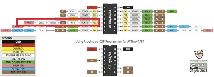
I kept on reading until I read this :
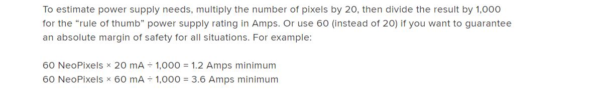
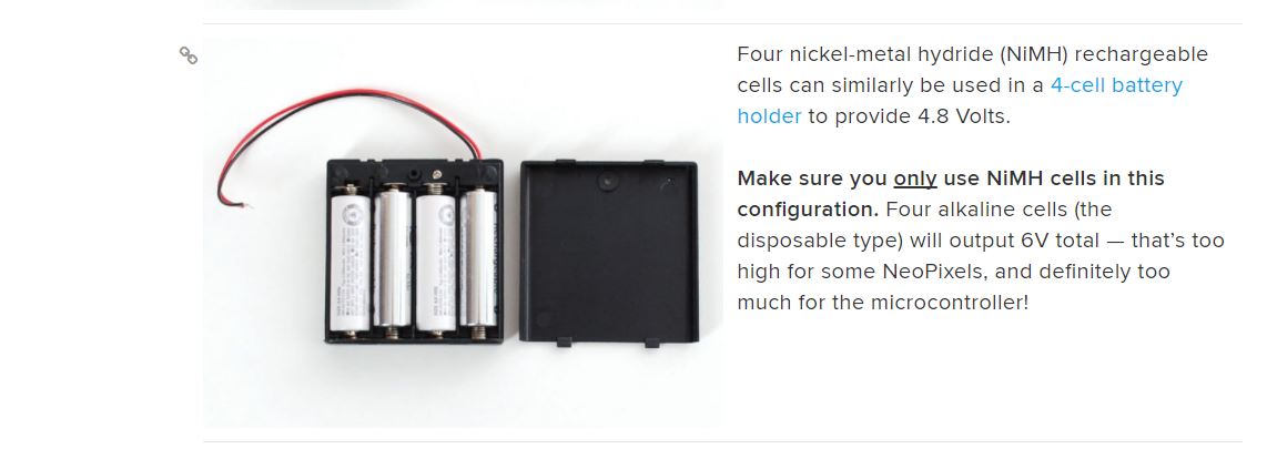
That was a problem because I wanted to power my board and the strip of led whit a 9V battery but I didn't find an SMD voltage regulator that gives in output 5V and more than 1Amp,so for this week assignment I powered the Strip whit the bench power supply we have in our lab and for my final project I'll use a 4-cell battery holder like this :
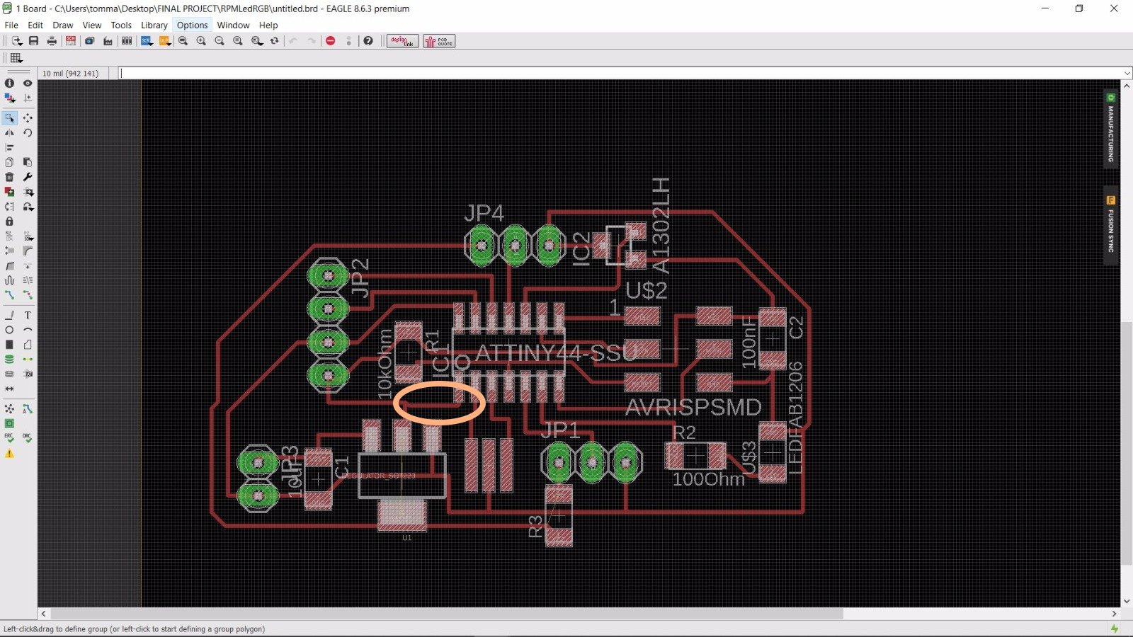
Designing the electronic Board
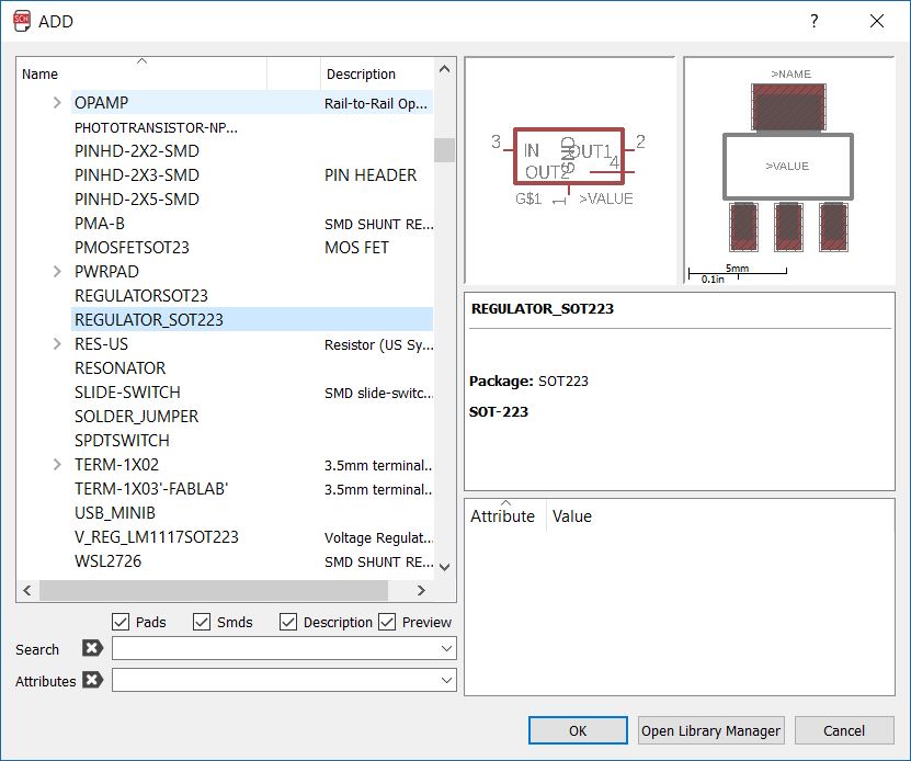
Using Eagles as always,the designing process wasn't hard.I provided my board whit a Voltage regulator to be powered whit a 9V battery, and with an HallSensor because I want this board to calculate RPM of the tubines in the near future.I also provide exposed pins for the Bluetooth module I'll use for Networking and communicationI found the package for the voltage regulator in the fab's library :
and the package for the hall sensor in the Allegro's library :
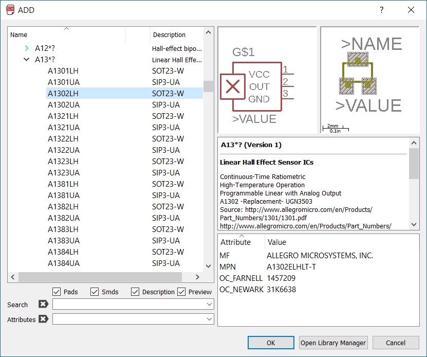
The hall sensor we had is a ratiometric sensors that provide a voltage output proportional to the applied magnetic field (link).So I connect the output of the sensor to an ADC pin.
The pins for the bluetooth didn't need much attenction because I'll use SoftwareSerial,so I choosed 2 of the remaining available pins.
Hold the left button on images to zoom in
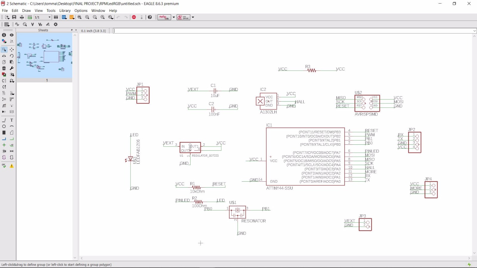
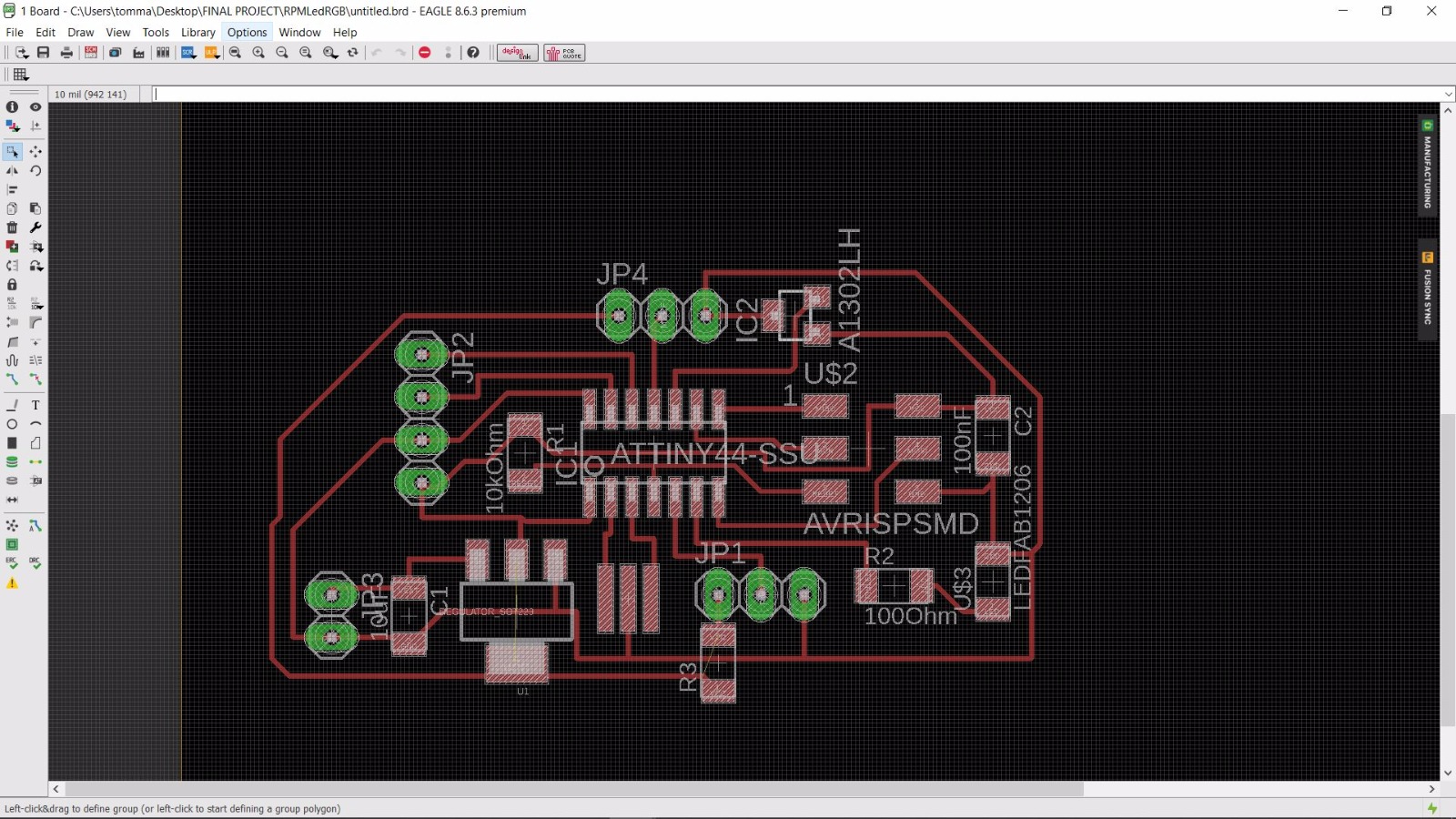
Actually the image above is the fixed version of the board.Previously I forgot to make this link :
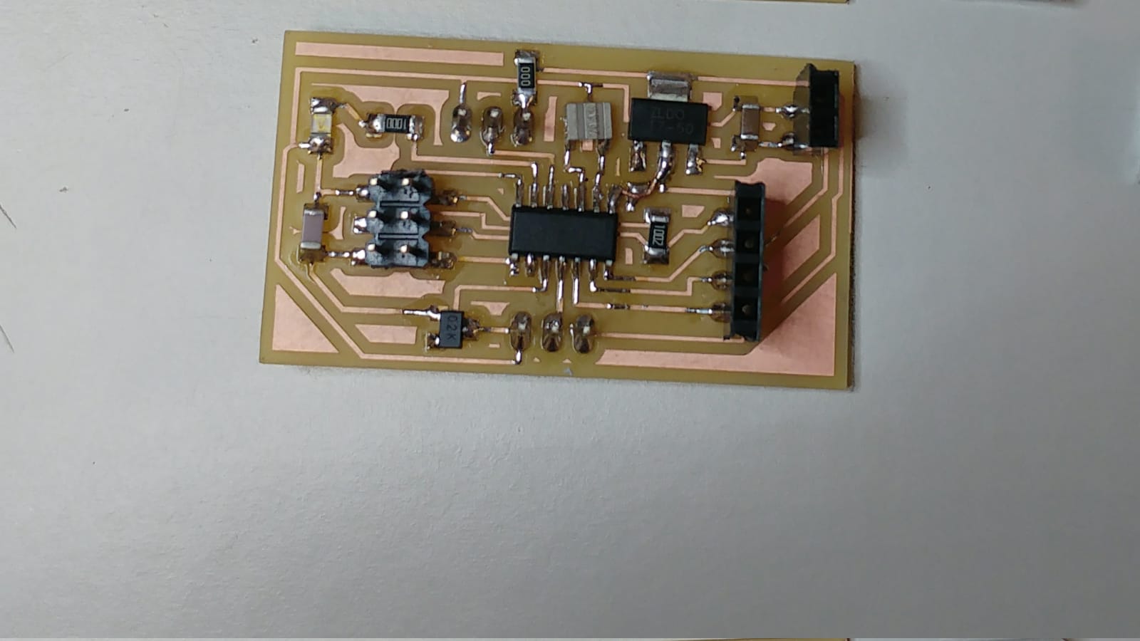
And I saw it only when I was soldering the ATtiny 44.At the moment I fixed it whit a small piece of a copper wire :
Code
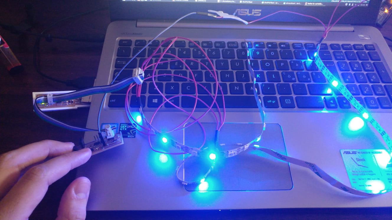
Once I was ready i followed this tutorial to install the Neopixel library and to lear how to control the strip.It has everything you need to know.To set the fuses according to use 8Mhz internal clock (20Mhz is too much for the neopixel strip) I burn the bootlooder once i made this change : Arduino IDE --> tools --> clock --> internal 8Mhz .Then I flashed the standTest modified version for my board whit the my USBtinyISP ( so the bootlooder has been overwritten)
I made this test at home and I powered the strip via an Arduino UNO.Even if they were not so bright,due to the power supply that couldn't provide much current,it worked!