Things to do :
- Group:Find the kerf value
- IndividualCut something on the vinylcutter
- IndividualDesign and make a parametric press-fit construction kit
Vinyl Cutter
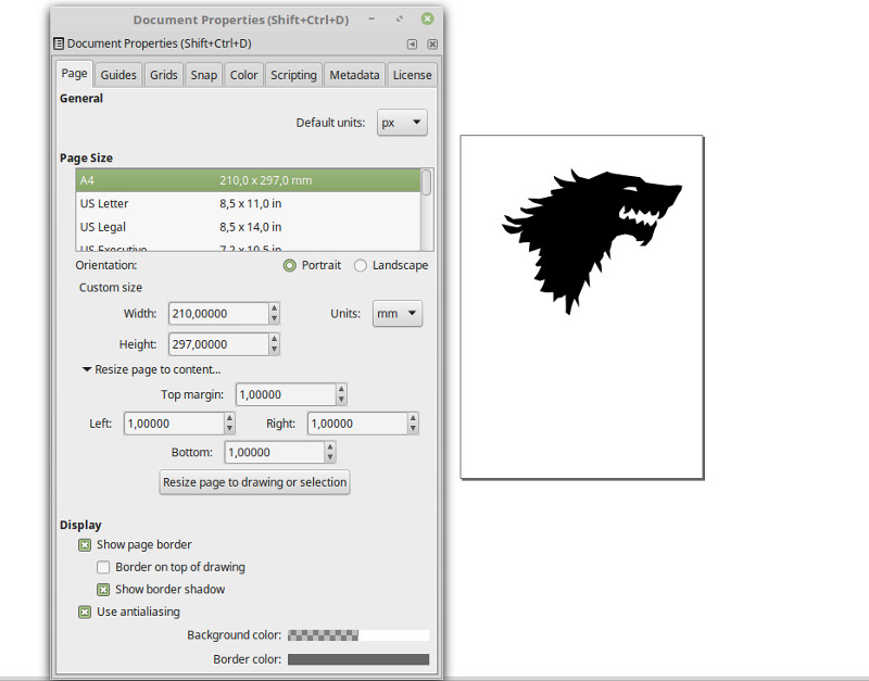
For the first assignment of this week we had to cut something on the vinylcutter.I downloaded the Stark's family crest (Game of Thrones) from internet choosing an image whit white background color,in order to easily work whit it. I imported the image in inkscape and vectorized it :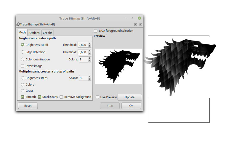
Then I resized the canvas to the dimentions of the image.
Before:
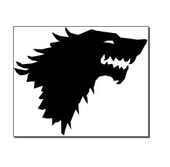
After:
And then I saved the img in .png .After all this steps I had to create the file .camm to make it readable from the vinylcutter.For this purpose there is FabModules.
FabModules
I loaded the image onto the FabModules,selected .png as input format and Roland Vinyl(.camm) as output format.Hold the left button on the image to zoom in
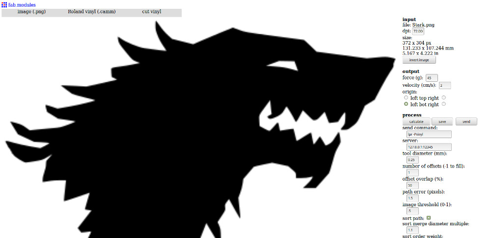
Problem : The size I saw in the top-right corner weren't the one I expected to be :
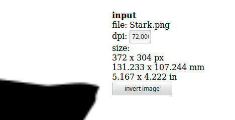
Size expected (values of inkscape):
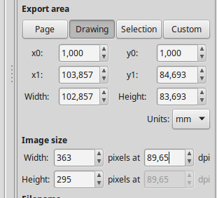
Solution : the DPI weren't the same!
After that I setted the Cutting Force = 70g,the Cutting Speed = 2 cm/s and the Origin = left bot right.Then the module calculated itself the cutting line and I downloaded the .camm file.
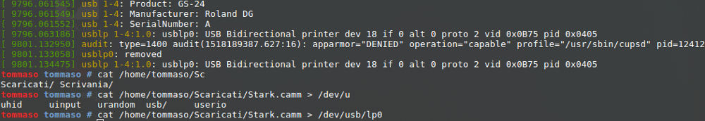
Before I send the file to the cutter ,I checked if the machine was recognized by the computer using the command :
dmesg
Then I send the image to the cutter whit the command :
cat /path/to/file/filename.camm > /dev/usb/lp0
I peeled out the scraps of the sticker and used paper tape to transfer it to my pc.

Laser cutter and Press-fit kit
For the second assignment of this week I decided to design the parametric kit whit solidworks.I learned the basics of this software previously(week 2,but never used it for parametric design.We had to use 5.8 / 6 mm thick plywood for this construction kit.(Here is the link to the group assigment where you can find the calculated kerf ).
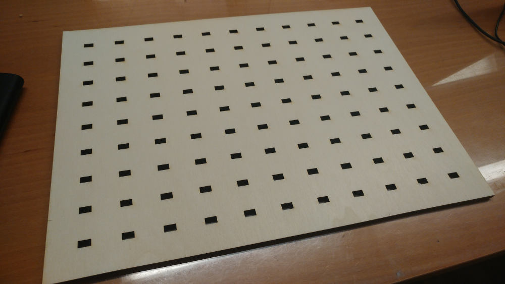
To use the parametric feature I defined the variables and the function I needed for my kit. The kit I made is a PegBoard.
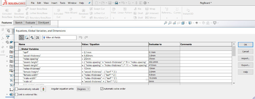
The height and the lenght of the board aren't a settled measure, but they vary whit the number of holes you want in the two axis, in order to center the grill of holes.In my instance 11x9.
The first parametric dimension
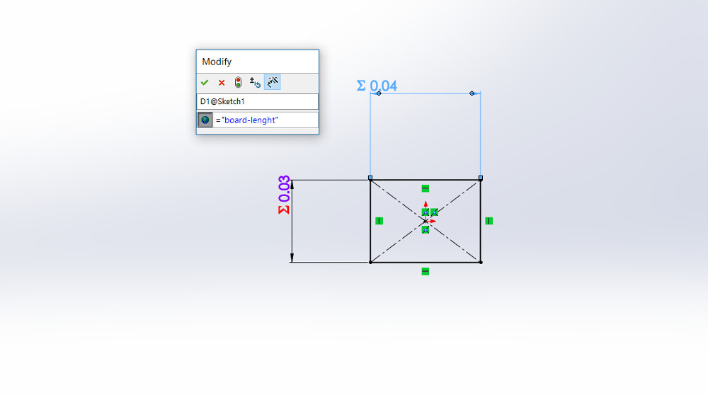
TIPS: look at the picture above this line.You have to type in the equal sign before the name of the variable.If you don't do that the dimension will be the dimension you specified for the variable,but if you change the value of the variable the dimention won't change.
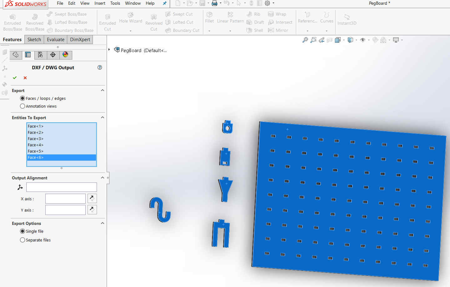
At the end of the designing process I saved the file as .DXF and I chosed the faces that I wanted to cut.
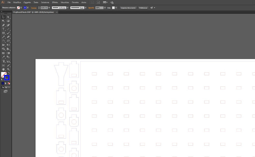
After that I moved on the pc that is linked to the Laser Cutter (Trotec Speedy 400 Flexx) , opened the file whit Illustrator and changed the size of the line to 0.001mm. Then I colored the line that I wanted to be cutted first in red and the other in blue (RGB colors).
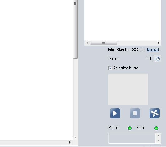
I printed the file and chosed the Trotec speedy 400 as printer,it will open the JobControl of the Laser Cutter.I checked if the cutter was linked and ready to cut:
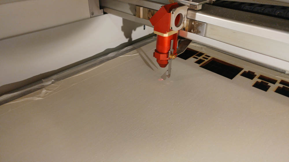
I setted the right distance from the lens to the plywood(whit the tool of the image below) and positioned the laser on the point that I wanted to be the origin.
I dragged and dropped the file to be cutted in the bottom-right corner of the origin:
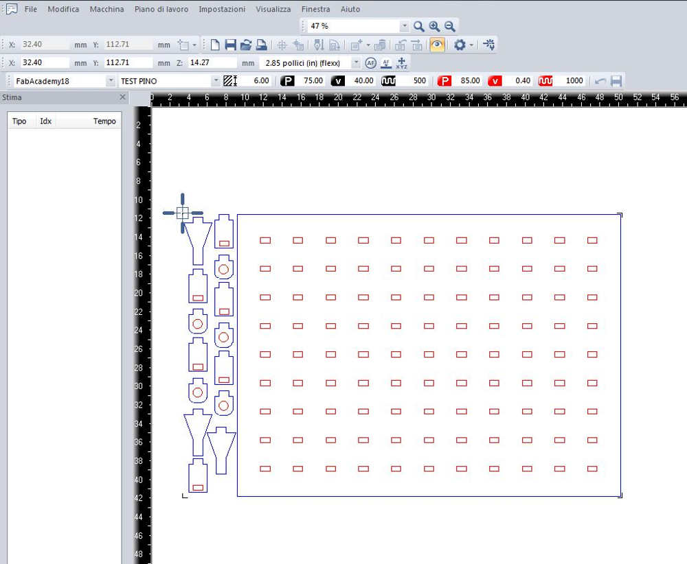
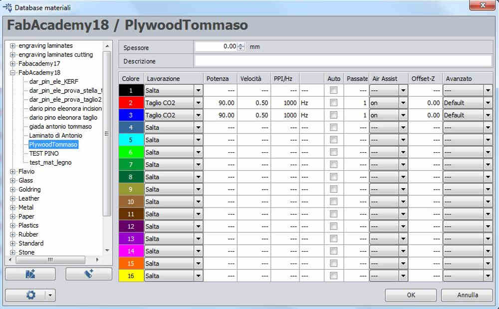
As I said before,I colored the line that I wanted to be cutted first in red and the others in blue.The reason why I did that is because the LaserCutter follow this table(If the parameters are setted).
I Checked if the estimated cutting time were a reasonable time:
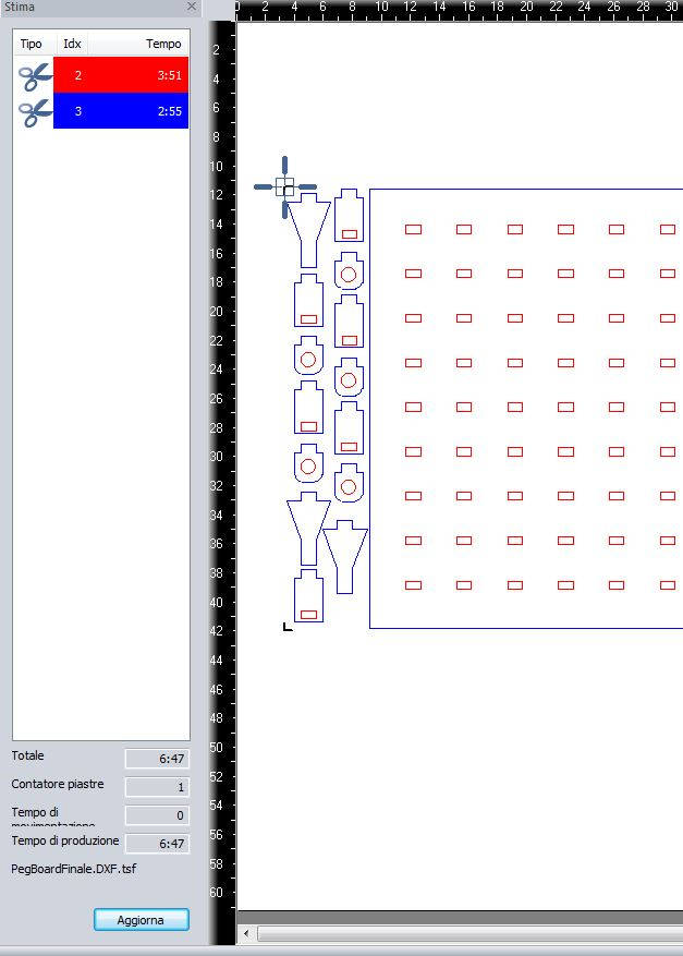
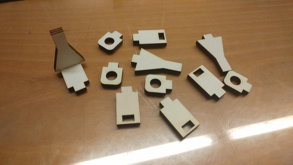
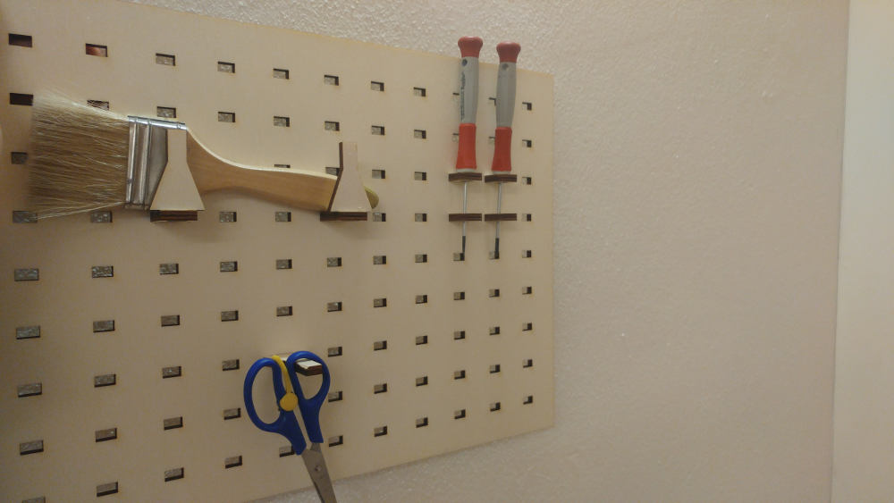
And there is the final results: