1. Basic Knowledge about laser cutter
Laser cutting is a technology that uses a laser to cut or engraving materials, and is typically used for industrial manufacturing applications, but is also starting to be used by schools, small businesses, and hobbyists. Laser cutting works by directing the output of a high-power laser most commonly through optics. The laser optics and CNC (computer numerical control) are used to direct the material or the laser beam generated. A typical commercial laser for cutting materials involved a motion control system to follow a CNC or G-code of the pattern to be cut onto the material. The focused laser beam is directed at the material, which then either melts, burns, vaporizes away, or is blown away by a jet of gas, leaving an edge with a high-quality surface finish. Industrial laser cutters are used to cut flat-sheet material as well as structural and piping materials.

- In 1965, the first production laser cutting machine was used to drill holes in diamond dies. This machine was made by the Western Electric Engineering Research Center;
- In 1967, the British pioneered laser-assisted oxygen jet cutting for metals;
In the early 1970s, this technology was put into production to cut titanium for aerospace applications. At the same time CO2 lasers were adapted to cut non-metals, such as textiles, because, at the time, CO2 lasers were not powerful enough to overcome the thermal conductivity of metals.
reference from Wiki
The basic structure of laser cutter

The basic Laser path of laser cutter

The nozzle of laser cutter

The process of laser cutter

The material we can use

Small laser cutter


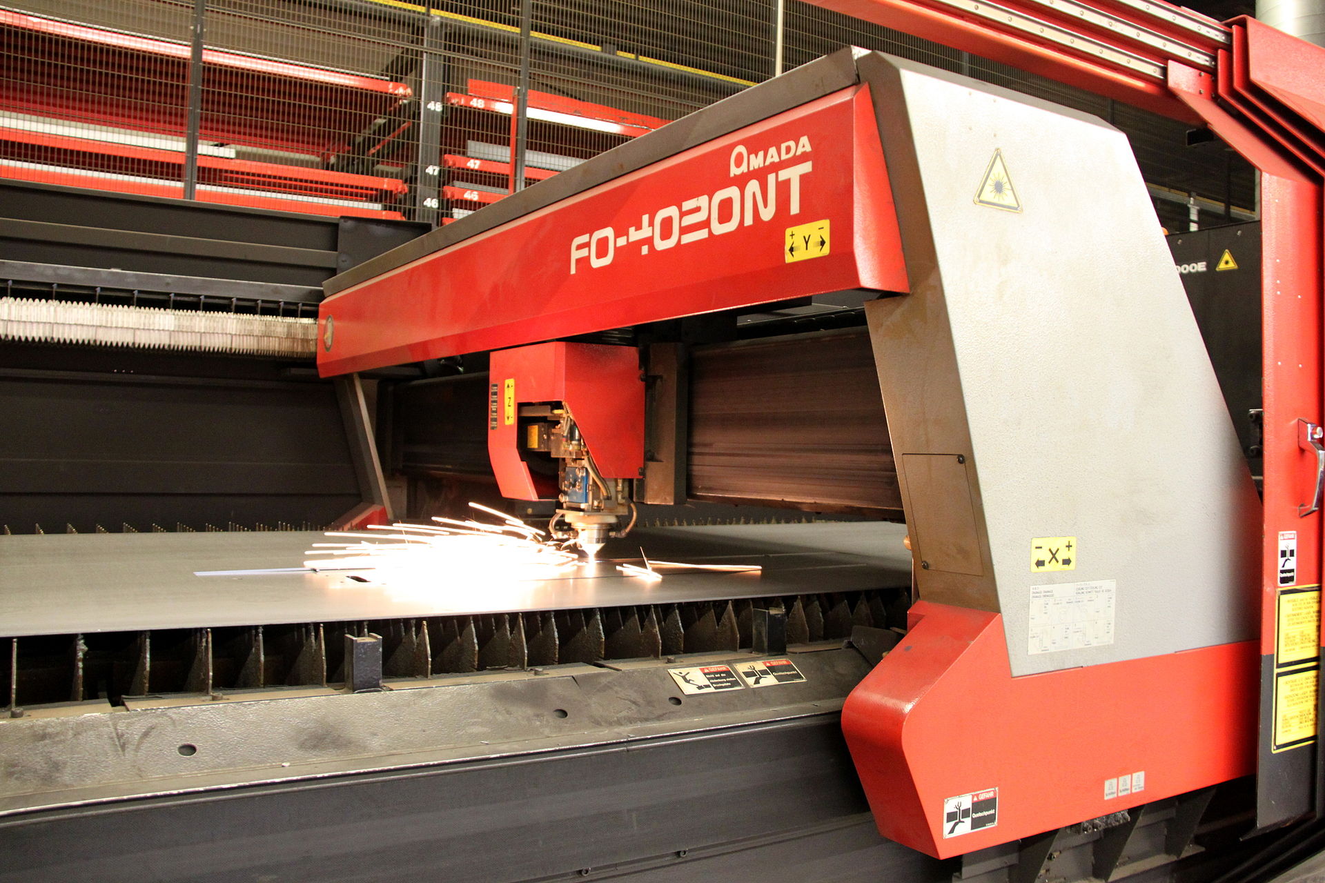
- Industry laser cutter

2. Safety
2.1 Laser safety
Most types of lasers operating in the visible and near infrared regions are sufficiently intense as to represent a hazard to the eye. Although damage may be caused to all parts of the eyes, the most vulnerable part is the retina, on which the beam may be focussed by the eye lens resulting in the destruction of tissues and the creation of permanent blind spots. High power lasers can also damage the skin. Only trained peaple can operate the machine, and we must close the enclosure before run the machine.
2. 2Laser classes: The current laser classes in national laser classes are: 1, 2, 3A, 3B and 4. The class of each laser must be marked clearly by the supplier.
- Class 1:It is safe in the reasonable working condition, and no specific safety controls are required.
- Class 2: Wavelength range from 400nm to 700nm, visible lasers
- Class 3A: Lower risk than 3B, but direct viewing of beam usually safe
- Class 3B: Intrabeam viewing not safe to the eye, diffusely reflected beam usually safe to the eye, assumed to be safe to the skin.
- Class 4: Those that generate the hazardous diffusely reflected beam, which may be harmful to the eye or skin, and can present a fire hazard.
During normal operation, the machine is enclosed and laser classification is Class 1. In normal usage the interlocked machine does not allow exposure to any dangerous laser radiation. The cutting chamber is fully enclosed during standard operation and keys are needed to access all body panels that open. In school's safety rule,laser operator need wear normal PPE (Laboratory coat, Safety glasses, Dust mask).
3. Practice in Fablab Shanghai
In group working,My classmate Xi.tingxia and I learn it in Fablab Shanghai and do the basic practice.
3.1The basic the condition of Laser cutter(troteclaser Speedy 300)

| Type | parameter |
|---|---|
| Laser type | CO₂ laser |
| Work area | 726 x 432 mm |
| Max. workpiece height | 125 - 305 mm |
| Machine size | 1128 x 911 x 1054 mm |
| Laser power | 10 - 120 watts |
3.2.Design in AutoCAD
- We design a demo which can check the best parameter(power and speed).So we design 5 pcs cutting demo(the power is 100%,90%,80%,70%,60%) and 5 pcs engraving demo(the power is 60%,50%,40%,30%,20%). The speed are 20mm/s,30mmmm/s,40mm/s,50mm/s,60mm/s,70mm/s;


We change the color to make sure the laser cutter software's requirment(JobControl require the color in design file the same as the RGB color in JobControl or the software can't red it)

Then we output "test.dxf" file and it can edit in CorelDRAW

3.3.Load plywood
The thichness in laser cutter is 3mm, and the honeycomb platform will hold the board and small waste material will drop down

3.4 Check the focus point
We can rise the platform and slow down when the measure apparatus almost touch the plywood.We stop rising when measure apparatus touch the plywood.
 Then close the Lid and prepare cutting.
3.5 Data translate
We would translate in CorelDRAW and then slice data to G-code
- In CorelDRAW,we import the "test.dxf" into CorelDRAW using the command File > Import (Ctrl+I).Then print the design
  - In Jobcontrol software, Add test file ,and reference (array1)

- Click "eye button"(array2) to Show the content of test file
- Double click empty space in workingspace or "setting" (array 3) to setting parameter.Define the power and speed The Heart of JobControl®. Predefi ned settings for different standard materials help we achieve the best possible engraving and cutting results.In this test we use plywood 3mm thickness. In addition, we can also save and manage your own materials

- Click Ready(array4)and operate the laser cutter
- Wait for several minutes (the fan and smoke filter will filte some waste smoke ),then open the lid and take out the demo

Because the time is limit, so I continue do my working in our school's lab
4. Practice 2 in UNNC's PDM lab
I do it in our school(UNNC)'s PDM lab. I use 60w redsail CO2 Laser cutter to do the second part of laser cutter practice
 The basic the condition of Laser cutter(redsail M900)
| Type | parameter |
|---|---|
| Laser type | CO₂ laser |
| Work area | 600x900 mm |
| Max. workpiece height | - |
| Machine size | 1500x1060x1140mm |
| Laser power | 60 watts |
4.1 Test1:Parameter test
I do it to finish fablab parameter test, becasue I didn't finish all of them and the machine is different,so I do it again.


The result is the following:
| Material | Thickness | Cutting | Power(%) | Speed(mm/s) | Engraving | Power(%) | Speed(mm/s) |
|---|---|---|---|---|---|---|---|
| Plywood | 1.0mm | Cutting | 80 | 35 | Engraving | 20 | 80 |
| Plywood | 2.0mm | Cutting | 80 | 30 | Engraving | 20 | 80 |
| Plywood | 3.0mm | Cutting | 80 | 20 | Engraving | 20 | 80 |
| Cardboard | 1.0mm | Cutting | 60 | 40 | Engraving | 20 | 80 |
| Cardboard | 1.5mm | Cutting | 90 | 30 | Engraving | 20 | 80 |
| Cardboard | 3.0mm | Cutting | 100 | 20 | Engraving | 20 | 80 |
| ABS | 1.0mm | Cutting | 60 | 20 | Engraving | 10 | 80 |
| Acrylic | 1.0mm | Cutting | 100 | 30 | 1 | 1 | 1 |
| Acrylic | 2.0mm | Cutting | 90 | 25 | 1 | 1 | 1 |
| Acrylic | 3.0mm | Cutting | 100 | 18 | 1 | 1 | 1 |
4.2 Test2:Kelf test
 I use this test to make sure the kelf,In design model ,the rectange is 10x10mm
 And the
 kelf=(110-107.6)/(11+1)=0.2mm
4.3 Test3:Engraving effect
According to test2, the parameter I use in this test is (speed 20mm/s, power 80%)

4.4 Press-fit construction kit(parameter design)
- Design 3D model in Fusion 360 the basic shape is Hexagonal. Then made a connection method(in this part I didn't add kelf),and I would add it in Autodesk CAD.

I need to consider the kelf, so I use parameter design to update it as following:


The equation is the following:

- Input in CAD(reference the document in week3_computer_aided_design/3D_Design_Fusion360-Drawing)
- Check the kelf again ,I choice the kelf 0mm, and 0.2mmm and after assembly it ,the left part(kelf 0.2mm) is good ,and the result verify the kelf in "4.2 Test2:Kelf test "

- According the above experience, I design the following 6 kinds of model

Use laser cutter to cut the board and take it out

- Assembly 1: Flat shape
 I use four kinds of model to assemble them together and it make several different kinds of sharpe. the above picture is 4 kinds of assembly case
 Assembly 2: 3D model
 I use all of the model to assemble them together, and the above picture is a test in 3D model.
In future, I would optimize the structure of the basic model to improve the following aspect
- Compare different material to find better one (the plywood is easy to broken)
- Optimize plug structure and enhance the strength
- Design another plug method and make it has more opportunity to connect them together
4.5 Penbox Practice
The design is finish in Fusion page
Machine ready
- Turn on Chiller unit, allow 10minutes stabilization before running it
- Release top ’Stop’ button
- Unlock interlock
- Switch on red side ’ On’ switch
- Insert material&clamp
- Close safety enclosure
- Switch on Infrared switch
- Plug in compressor and turn on Extractor fan
Data :Insert key and start up software and translate data from pc to laser cutter
- I use the design data from fusion 360 last time I design.So I would download the data from Sheet1.dxf-sheet6.dxf
- Import data:Open software(easycutter),then
file - import- data(sheet1.dxf-sheet6.dxf)
Machine operating
- Test the profile
- Switch on Laser switch
- Press ‘Start’ on machine to process
- After cutting has finished, turn off Laser switch
- Open safety enclosure and remove parts
Stop machine
- Turn off Extractor fan and Unplug Compressor
- Switch off infrared switch
- Depress top ‘Stop’ switch
- Lock interlock
- Switch off red side switch
- Turn off chiller unit
The following is the picture to show the condition of laser cutter


