Input device
1.Assignment
individual assignment:
Measure something: add a sensor to a microcontroller board that you have designed and read it
group assignment:
Measure the analog levels and digital signals in an input device
2.Aim
- Learn how to use NTC thermistor as input sensor to measure the environment temperature;
- Practice Attiny 44 as the chip
- According to the temperature control output device ,such as LED in this test
- Use switch to control two program (different method to give signal)
3. EAGLE Design
3.1 I learn the basic about NTC sensor
It does so by using a thermistor, a resistor which responds to temperature, as the environmental sensor.
 we can use the analogue digital conversion (ADC) pins on the ATTiny44 to read the change voltage caused by change in resistance/temperature. The Wheatstone bridge provides a simple solution to this: two pairs of 10K resistors branch off from VCC, acting as a voltage divider, meaning that R1/R2 = R3/R4. In this case, R1-3 are 10K resistors and R4 is a 10K thermistor. Each branch goes into a different ADC pin on the ATTiny. To measure the change in resistance, we can compare the change in voltage between the two sets of resistors
According to the above guide, and with the help of Fab's board. I practice it in EAGLE
we can use the analogue digital conversion (ADC) pins on the ATTiny44 to read the change voltage caused by change in resistance/temperature. The Wheatstone bridge provides a simple solution to this: two pairs of 10K resistors branch off from VCC, acting as a voltage divider, meaning that R1/R2 = R3/R4. In this case, R1-3 are 10K resistors and R4 is a 10K thermistor. Each branch goes into a different ADC pin on the ATTiny. To measure the change in resistance, we can compare the change in voltage between the two sets of resistors
According to the above guide, and with the help of Fab's board. I practice it in EAGLE

3.2 BOM
According to my aim, I list the following BOM list
| Name | quantity | mark |
|---|---|---|
| ATtiny44 | 1 | U1 |
| NTC | 1 | R9 |
| resistors (10kΩ) | 5 | R1, R2, R3,R4,R6 |
| resistors (499Ω) | 2 | R5, R8 |
| LED(red) | 1 | US1 |
| LED(green) | 1 | US5 |
| Slide switch | 1 | slide2 |
| capacitor(100NF) | 1 | C1 |
| pin header | 1 | 2*3 |
| pin header | 1 | J1 |
3.3 connection
I add component (reference electric design how to add component in eagle) and connect.

3.4 layout
Then go into BRD interface to optimize layout.

- Hand working to relocation the component
- Tool-ERC confirm the parameter of board
- Tool- Autorouter to optimize the path
- If there is some problem (two or more paths interference
),I would optimize the location of component and then Autorouter it till it is OK
4.Process
4.1 Output data
- Output png:
File-Export- Imageand then define some parameter according to the following figuare
- Use Photoshop to change the size, then invert the dawing,and make the 'trace' and 'outline'
- Define some parameter (reference electronic production)
4.2 Make it
This reference electronic production
- Load board;
- Load cutter(1/64'') and set the xyz origin position;
- Load trace file
- Cutting the trace and clean it
- Load cutter(1/32'') and set the xyz origin position;
- Load outline file
- Cutting the outline and clean it
- Unload the board;
- Use sandpaper and alcohol to polish the PCB board;
- Solder the components to the board according to eagle design and BOM
7.Test
ArduinoISP
Setting arduino the same as electronic Design
Connect
I connect the wire according the following
| New board | Arduino |
|---|---|
| slave reset | 10 |
| MOSI | 11 |
| MISO | 12 |
| SCK | 13 |
| VCC | VCC |
| GND | GND |
connect a 10 uF capacitor between RESET and GND.
Code
I want to come true the following function
- NTC can get the environment, and the slide switch can change the range of measure .
- If choice range1(slide switch) ,the LED1(US1) will shine when temperature more than 40,the LED2(US5) will shine when temperature less than 10;
- If choice range2(slide switch) ,the LED1(US1) will shine when temperature more than 80,the LED2(US5) will shine when temperature less than 40;
I have learn some basic information in fab as following
9. Atmel 328- NTC
I find new method according to another informationArduino NTC.
 So I change to this method
9.1 Test on Arduino
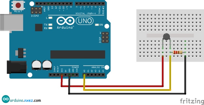
In Arduino (with Atmel 328 chip ),we will use the following method to connect it .

So I connect this component with Arduino Then I program the code as the following:

During run the test, I use electric hair dryer to simulate high temperature, and the following picture show that temperature rise from 40 -56 in about half minutes.
The test for NTC in Arduino is OK.
9.2 Board design
Becasue of limit time ,so I do it as a part of my finial project.
I get the help of my instructor Silli Saverio. I design my board and learn from Daniele Ingrassia's Satshakit
In the meantime atmel 328 is the chip of Arduino , so I can take the following picture for reference
 In Satshakit's board, the left part is the same.
 So I delete the right pin and keep the left part of the board.And design another function in eagle. This is the basic of the PCB board.
 I would use FTDI cable to program the board. So I design connect FTDI to Atmel 328 in the following picture
 According to the test in "2.1 Test NTC",I add NTC and 50k resistor. and use A1(Arduino A1 correspond to pin24(PC1) in Atmel 328).
So I add NTC part in circuit
According to the test in "2.1 Test NTC",I add NTC and 50k resistor. and use A1(Arduino A1 correspond to pin24(PC1) in Atmel 328).
So I add NTC part in circuit
 I also design another functions, for examlple stepper motor,led ,etc, reference detail on the page of finial project-electronic
9.3 Manufacture
After design all of the board, I check with the schematic to confirm there is no mistake. Then we can go to the next stepI use the command  Generate/Switch to make the board
 The detail in layout can referene the WEEK 7: ELECTRONIC DESIGN-eagle practice-part5,it show the detail about creat basic board,creat a DRC design rule,move and rotate,output data.
At last I got the following result
The detail in layout can referene the WEEK 7: ELECTRONIC DESIGN-eagle practice-part5,it show the detail about creat basic board,creat a DRC design rule,move and rotate,output data.
At last I got the following result
 For the wire in the red array there is a wire I have to use jumper to connect.
Then I output 2files( trace.png ,hole.png)
For the wire in the red array there is a wire I have to use jumper to connect.
Then I output 2files( trace.png ,hole.png)

 Then I use SRM-20 Desktop Milling Machine to milling the board and solder the board.


9.4 Code test
Bootloader
This board is referenced from Arduino, I need to upload Arduino bootloader.
Here is the connection of my board with Arduino:
 In this time I find a problem, I forget that there is no pin for bootloader. So I have to solder new wire on the chip
 Then operate as following:
- Open Arduino IDE;
- Select proper programmer by click on
Tool->Programmer - Select Arduino UNO as Tool->Board
Click on Tools->Burn Bootloader
 It is OK.
To avoid the problem and make sure it is stable
In the meantime, during I do the test in stepper motor , there is an explosion (The Electrolytic capacitor has the requirment in positive and negative.But I connect reverse VCC12POWER and GND12POWER )
I update it to the following

test NTC
 I have NTC circuit and port on this board. So I just need to add NTC sensor on the board as following:
 Then program it (NTC arduino code in the attachment)
But I found I can't upload it . With the help of my instructor Saverior. I change the board choice in Arduino to "Arduino Pro or Arduino Mini"
Then program it (NTC arduino code in the attachment)
But I found I can't upload it . With the help of my instructor Saverior. I change the board choice in Arduino to "Arduino Pro or Arduino Mini"
 Then it is OK