WEEK 11 - INPUT DEVICES
INTRODUCTION
This week we will use skills gained the previous weeks like "Electronic Production", "Electronic Design" and "Embedded Programming" to connect and Input device to a board that we will design and program it to measure the input levels. I wanted to design a board that will serve my needs in my final project so the Input device I chose was IR phototransistor but unfortunately I did not find it in our lab inventory at the moment we are doing this assignment, so I decided to choose the closer match to it - the Visible Light Photo-transistor. My circuit will simply show the illumination levels and turn a LED on when the surrounding ambient is dark. The work I performed can be summarized in steps as follows:
- Circuit Design.
- Circuit Production.
- Circuit Programming.
Assignment Description
- Group Assignment: measure the analog levels and digital signals in an input device.
- Individual Assignment: Measure something: add a sensor to a microcontroller board that you have designed and read it.
Learning Outcomes
- Demonstrate workflows used in circuit board design and fabrication.
- Implement and interpret programming protocols.
Have you (Checklist)
- ✔ Described your design and fabrication process using words/images/screenshots.
- ✔ Explained the programming process/es you used and how the microcontroller datasheet helped you.
- ✔ Explained problems and how you fixed them.
- ✔ Included original design files and code.
TOOLS AND HARDWARE USED (BOM):
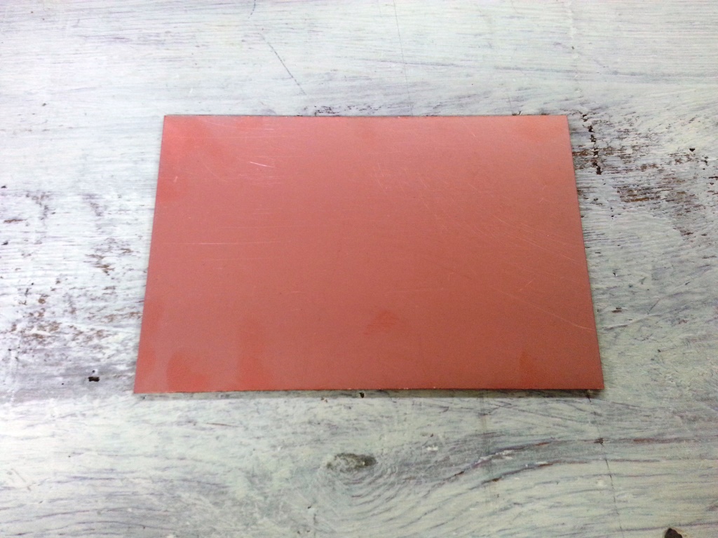
- 1 x FR1 (Copper PCB Board).
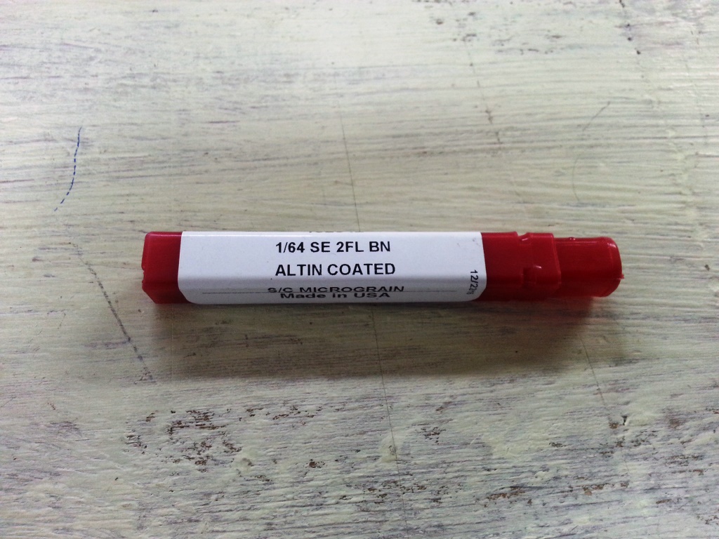
- 1 x 1/64 inch end mill bit.
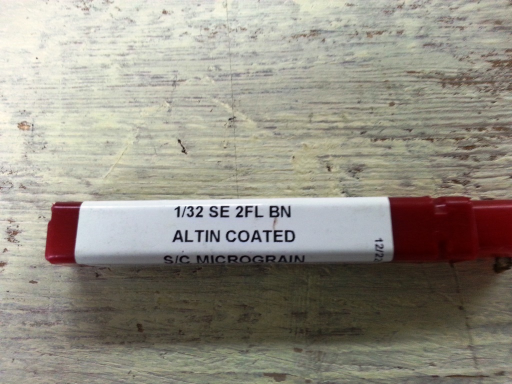
- 1 x 1/32 inch end mill bit.
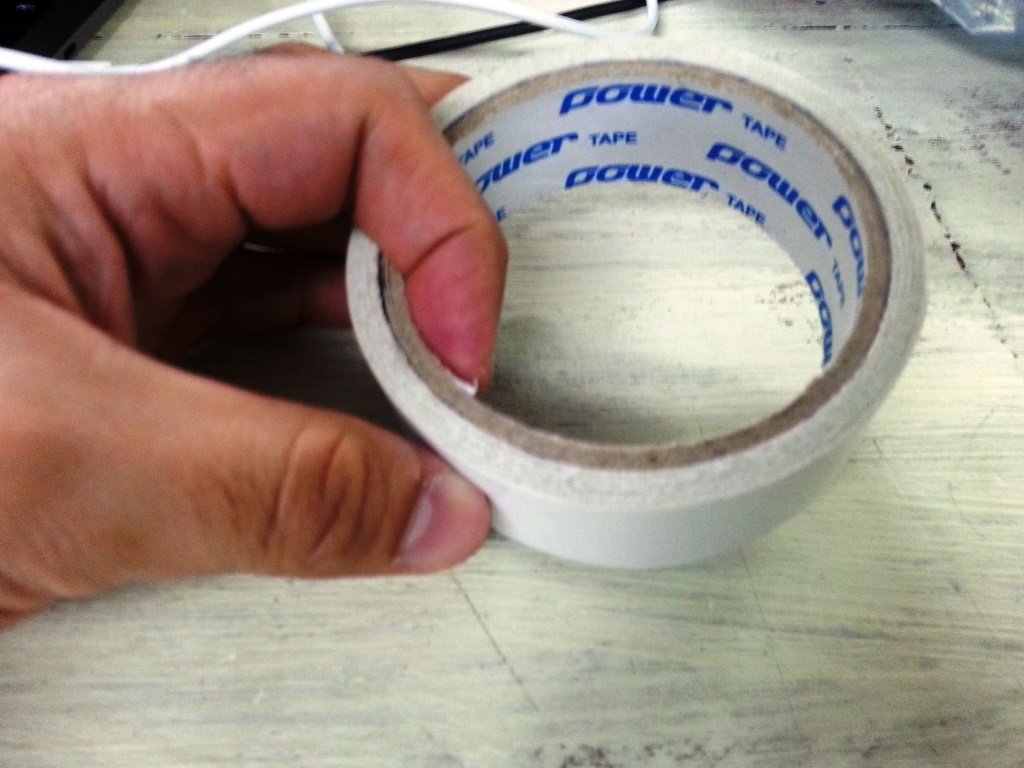
- 1 x double tape.
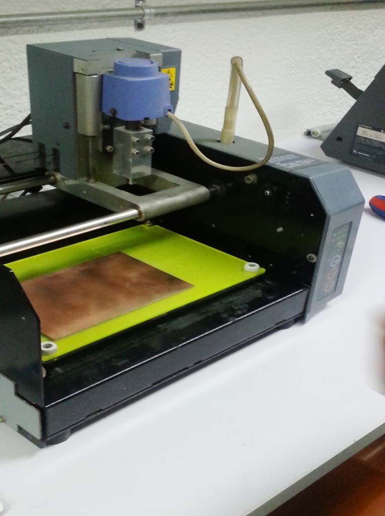
- 1 x Modela MDX-20 (More about the Machine can be found in THIS LINK
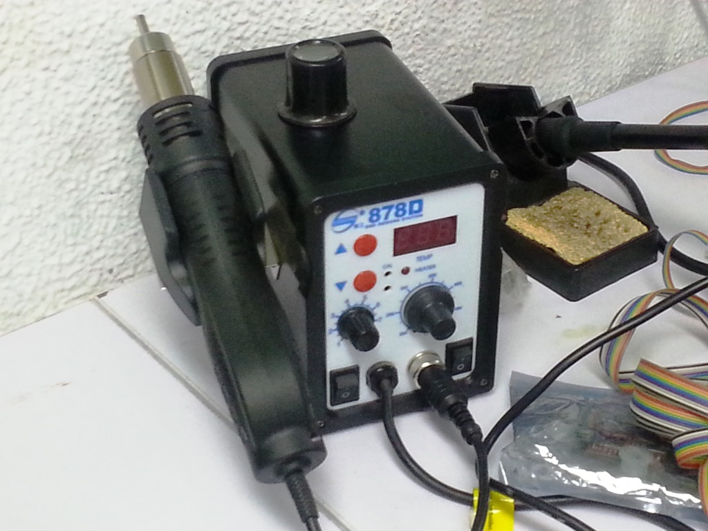
- 1 x Soldering Station.
- soldering wire
- AVO multimeter
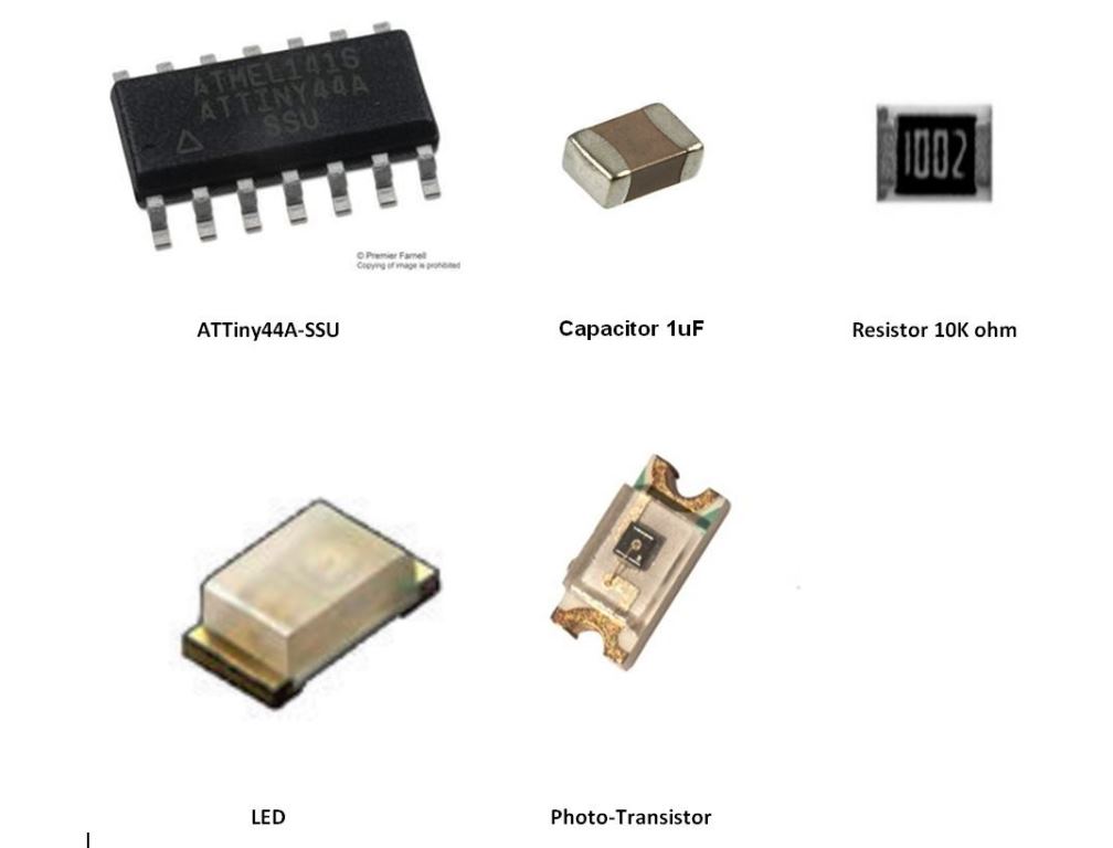
- Electronic Components Including:
- 1 x ATTiny45-SSU.
- 1 x (2x3) pin header for AVRISP
- 1 x (1x6)pinheader for Rx,Tx,VCC,GND
- 1 x LED.
- 1 x 1 uF Capacitor.
- 2 x 10k Resistor
- 1 x 499 Resistor.
- 1 x PHOTOTRANSISTOR 1206.
STEPS PERFORMED:
CIRCUIT DESIGN
- I decided to use Autodesk Eagle as a CAD tool to design the circuit, I followed the same steps that I performed in WEEK 7 electronic design assignment.
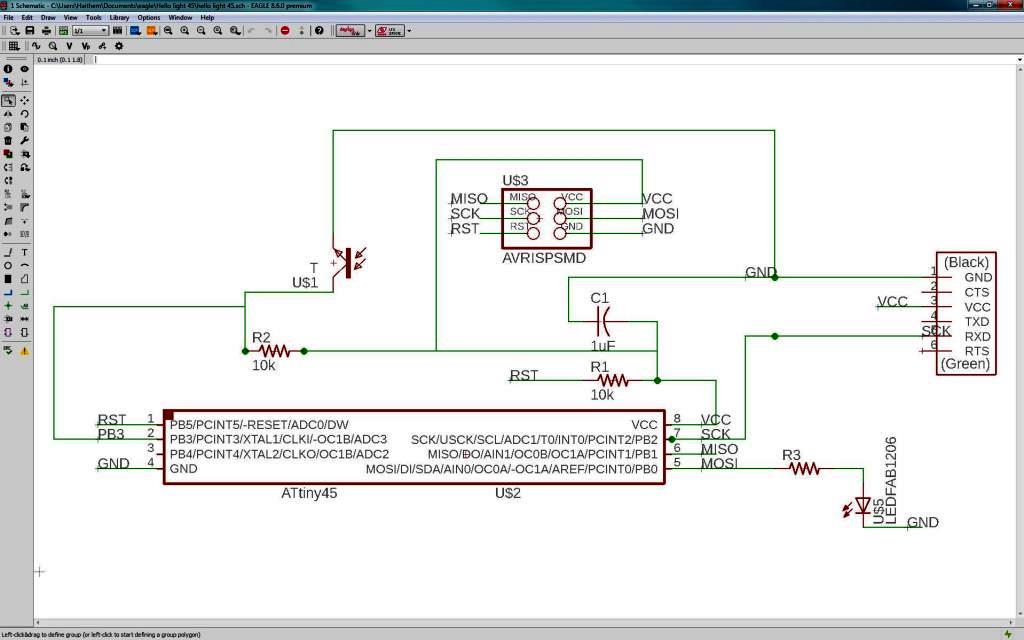
- To play it safe, I decided to use Neil Hello-Light circuit and modify it to add a LED that will change its state depending on the photo-transistor reading
- I started a new project and I then created a new schematic.
- I added the components to the schematic from the Fab library and I connected them to create the schematic shown in the diagram below.
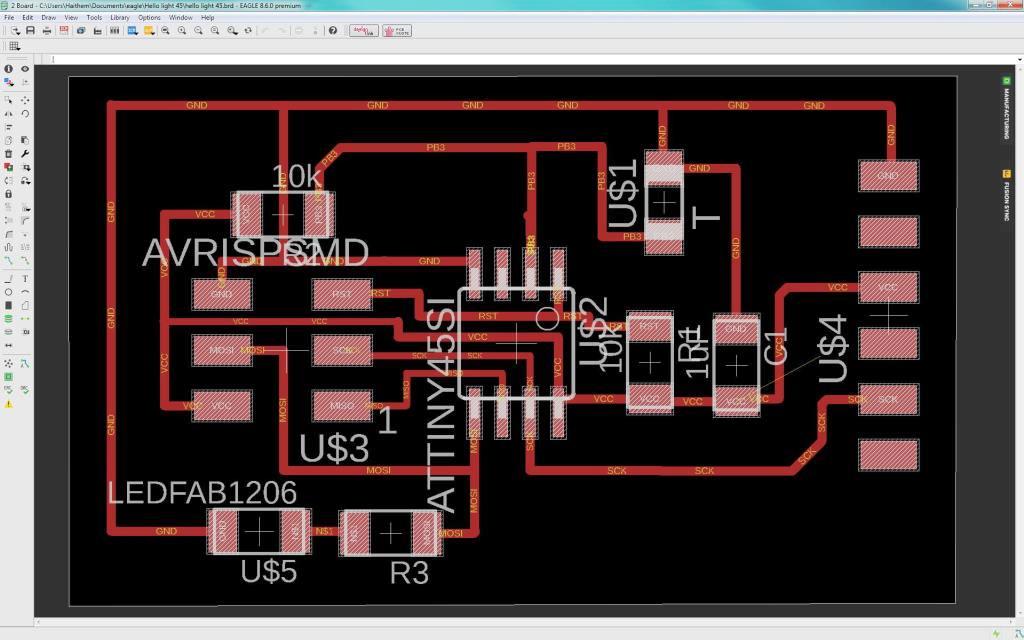
- I then switched to the board view by going to the top menu > File > switch to board. The board view will open up and components we just added will appear
- Use "move" to move each component around and "route" to route each trace. The wire will turn red as you route it into place.
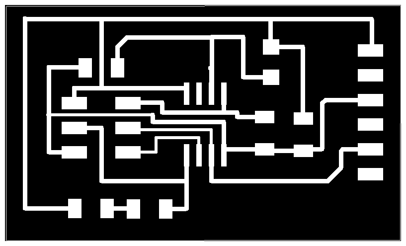
- Keep moving and adjusting the wires and components till you reach the final desired layout as shown below.
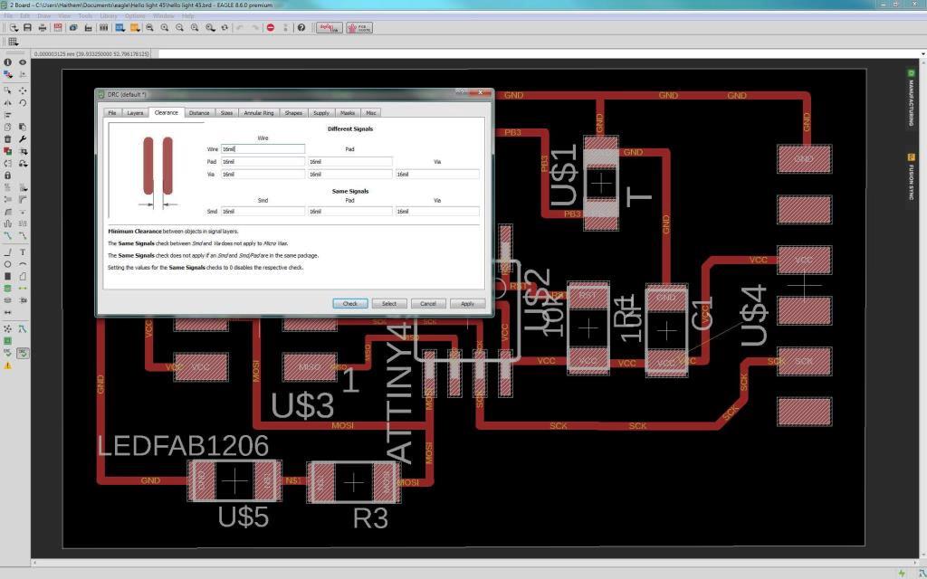
- After I finished the orientation and wiring the components in the board view I started to do the design check also known as DRC. the main purpose of te DRC is to ensure that the used 1/64 inch mill-bit tool will have enough clearance to mill around the traces and in-between them.
- a mill-bit with the diameter of 1/46 inch (~16 mil) is used; So I opened the DRC from The "Tools" menu. Then in the "Clearance" tab, I wrote "16mil" to all the fields there.
- Finally I started to export the circuit to PNG image and I edited them using GIMP to create the TRACES PNG FILE and BORDERS PNG FILE
MILLING THE CIRCUIT
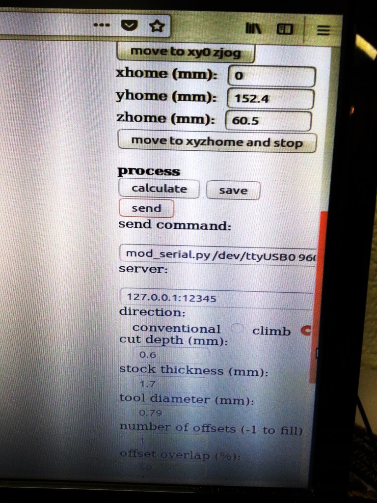
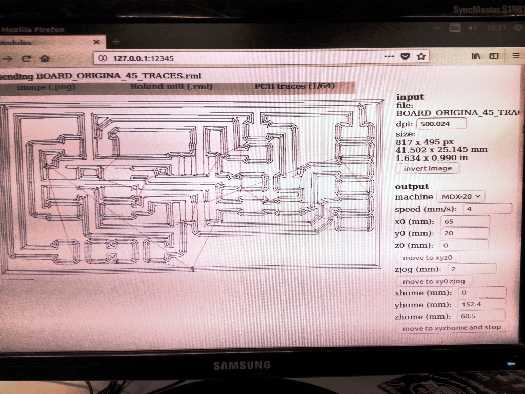
- I started milling the circuit PCB board on the Modela MDX-20 using Fabmodules and soldering the components follwoing the same principles we learned in WEEK 5
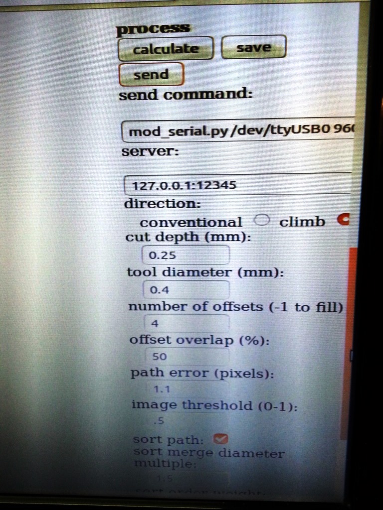
- For milling the traces:
- I used the 1/64 inch diameter end mill
- cutting depth = 0.25 mm
- number of offsets = 4
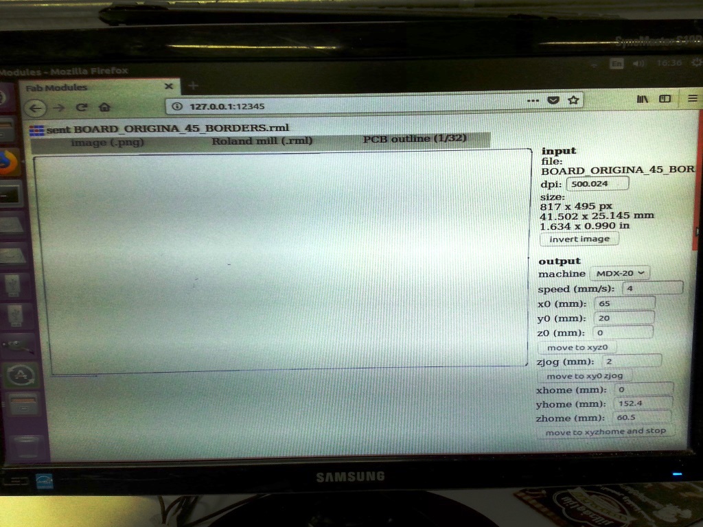
- For milling the borders:
- I used the 1/32 inch diameter end mill
- cutting depth = 0.25 mm
- cutting depth = 0.6 mm
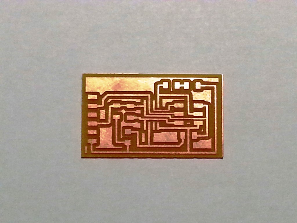
- I then started the milling as shown in hte video below
- When I created my board, I soldered the electronic components in the PCB circuit as shown below
IMPORTANT TIP!:
I was familiar of the polarity of all the components EXCEPT for the photo transistor, so I looked it up in the PHOTO-TRANSISTOR DATA SHEET where I found out that the the collector side has 2 side green marks.
I was familiar of the polarity of all the components EXCEPT for the photo transistor, so I looked it up in the PHOTO-TRANSISTOR DATA SHEET where I found out that the the collector side has 2 side green marks.
CIRCUIT PROGRAMMING
PROGRAMMING USING ARDUINO IDE AND FABISP AS A PROGRAMMER
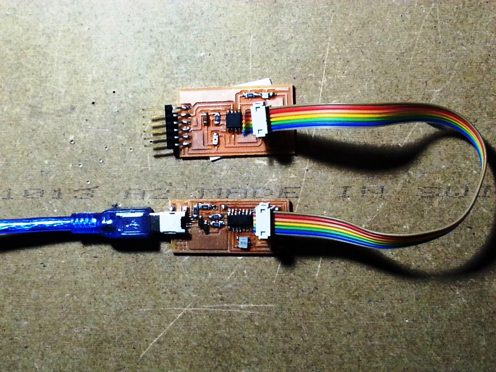
- Connect the FAB ISP pins to the Hello-light board pins with each pin connected to its corresponding similar pin as follows:
- MISO (in FAB ISP) -> MISO (in Hello-light Board)
- MOSI (in FAB ISP) -> MOSI (in Hello-light Board)
- SCK (in FAB ISP) -> SCK (in Hello-light Board)
- Vcc (in FAB ISP) -> Vcc (in Hello-light Board)
- GND (in FAB ISP) -> GND (in Hello-light Board)
- RST (in FAB ISP) -> RST (in Hello-light Board)
- Connect the FAB ISP to the usb Port and ensure it is detected by the PC.
- Connect the FTDI Cable to the FTDI header in the FTDI pins in the Hello-Echo Board.
- open arduino IDE then burn the BOOTLOADER.
- To burn the BOOTLOADER I followed the following steps:
- Select "USBTinyISP" under Tools > Programmer.
- Select ATtiny from Tools > Board.
- Select the specific ATtiny you are using (44/45/84/85) from Tools > Processor.
- Next select "8 MHz (INTERNAL)" from Tools > Clock.
- select "Burn Bootloader" under tools and wait till it complete.
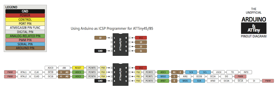
- I looked at the ATTINY45 Datasheet and the PINOUT map in the diagram below to identify the ARDUINO mapping of the Attiny45 pins
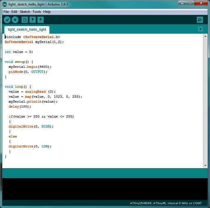
- I wrote the following code and below are few notes about the code.
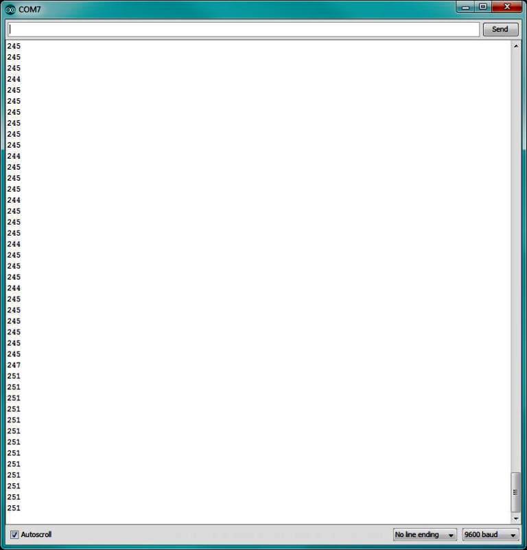
- To be able to view the readings of the analogue PB2 (ANALOGUE PIN3 IN ARDUINO), I configured a software serial where RX PIN = 1 and TX PIN = 2
- I set the OUTPUT PIN where the LED is connected to PB0 (ARDUINO PIN 0)
- I used map function to map the analogue readings to a range of values from 0 to 255. More about the MAP function can be found in THIS LINK .
- I tested the sensor till I identified that the room normal light is showing a value of 245 or less. so I set my threshold to 250 where any value above 250 is considered darkness and trigger the LED to be turned ON.
WHY DID I USE MAP FUNCTION?
The use of the MAP FUNCTION was not essential but rather more convenient, the aim was to ensure that the range where darkeness is detected is smaller and accordingly when I do comparison in my code to detect if it is dark or light, the range of values I compare to is smaller. In short I wanted to decrease the preceision!!.
The use of the MAP FUNCTION was not essential but rather more convenient, the aim was to ensure that the range where darkeness is detected is smaller and accordingly when I do comparison in my code to detect if it is dark or light, the range of values I compare to is smaller. In short I wanted to decrease the preceision!!.
- I compiled the code then uploaded it.
- The final result is as shown in the video file below.
Files: