WEEK 10 - MOULDING AND CASTING
INTRODUCTION
This week we are required to work on moulding and casting an object, I am pretty new and have never did this process before so the first question I had was what is the difference between moulding and casting and the answer was:
- Moulding: is the process of manufacturing by shaping liquid or pliable raw material using a rigid frame called a mold or matrix. This itself may have been made using a pattern or model of the final object. A mold or mould is a hollowed-out block that is filled with a liquid or pliable material such as plastic, glass, metal, or ceramic raw material. The liquid hardens or sets inside the mold, adopting its shape.
- Casting: is a manufacturing process in which a liquid material is usually poured into a mold, which contains a hollow cavity of the desired shape, and then allowed to solidify. The solidified part is also known as a casting, which is ejected or broken out of the mold to complete the process. Casting materials are usually metals or various cold setting materials that cure after mixing two or more components together; examples are epoxy and clay.
- MOULD DESIGN (Create the positive).
- MILLING THE MOULD.
- CASTING THE MOULD.
- CASTING THE MODEL.
Assignment Description
- GROUP ASSIGNMENT: review the safety data sheets for each of your molding and casting materials, then make and compare test casts with each of them.
- INDIVIDUAL ASSIGNMENT: Design a 3D mould around the stock and tooling that you'll be using, machine it, and use it to cast parts from it.
Learning Outcomes
- Design appropriate objects within the limitations of 3 axis machining.
- Demonstrate workflows used in mould design, construction and casting.
Have you (Checklist)
- ✔ Explained how you designed your 3D mould and created your rough and finish toolpaths for machining?
- ✔ Shown how you made your mould and cast the parts?
- ✔ Described problems and how you fixed them?
- Included your design files and ‘hero shot’ photos of the mould and the final object?
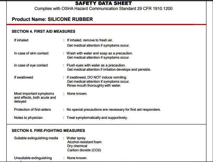
USED MATERIAL (SILICON RUBBER AND EPOXY) DATASHEETS
- For Silicone Rubber we did not find locally a provider who submit datasheet for the silicone ruber product but still to do a due diligence I looked-up the general characteristics of the silicone rubber on the internet and reviewed few sheets and I dound out the following:
- Avoid eating, drinking or smoking while use
- Use gloves during use and wash your hands after use.
- use in a plae with good ventilation.
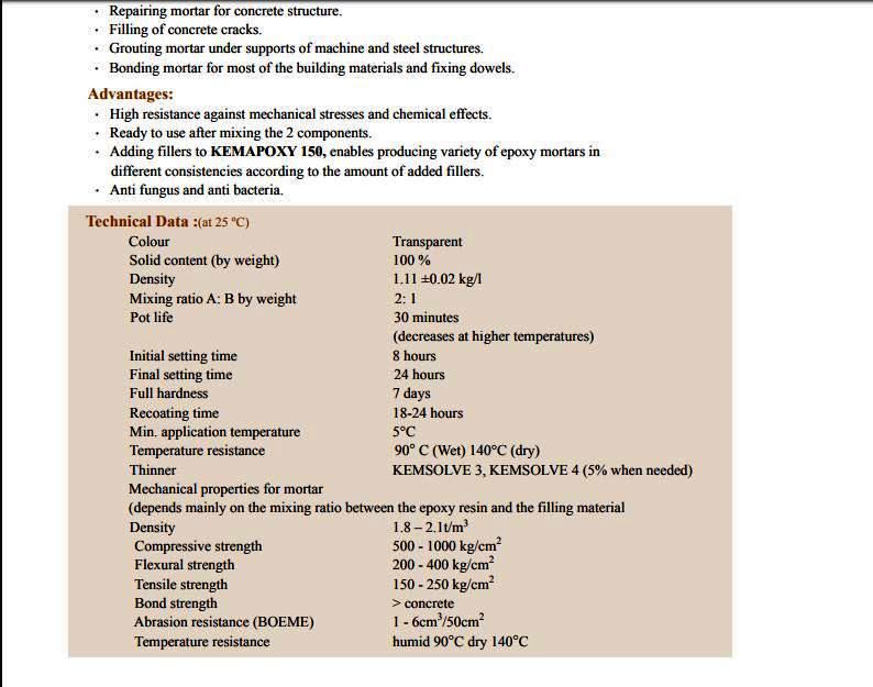
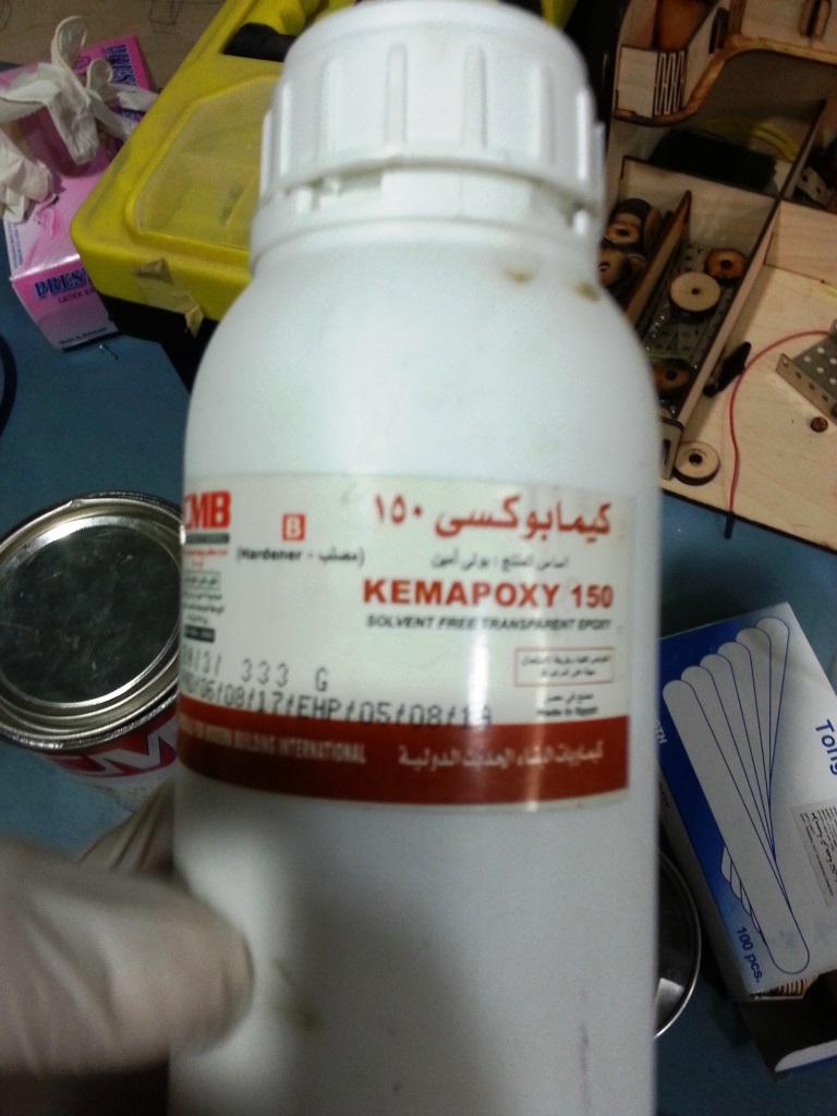
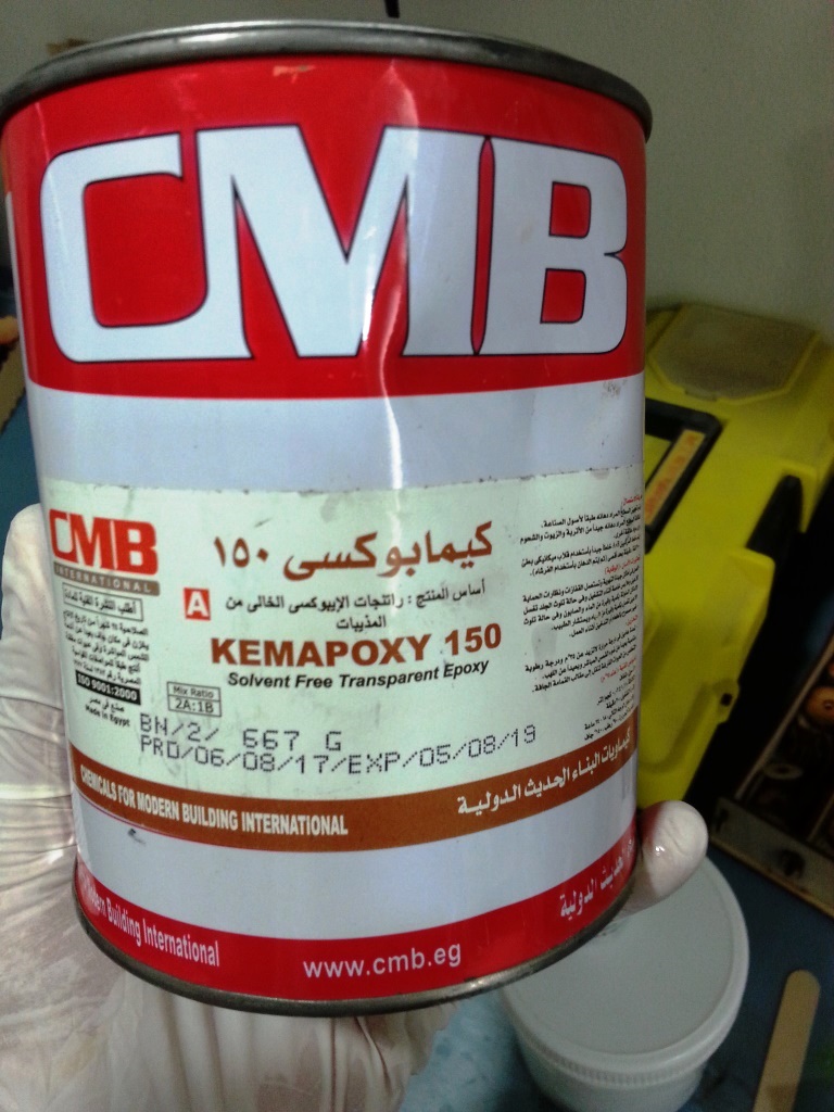
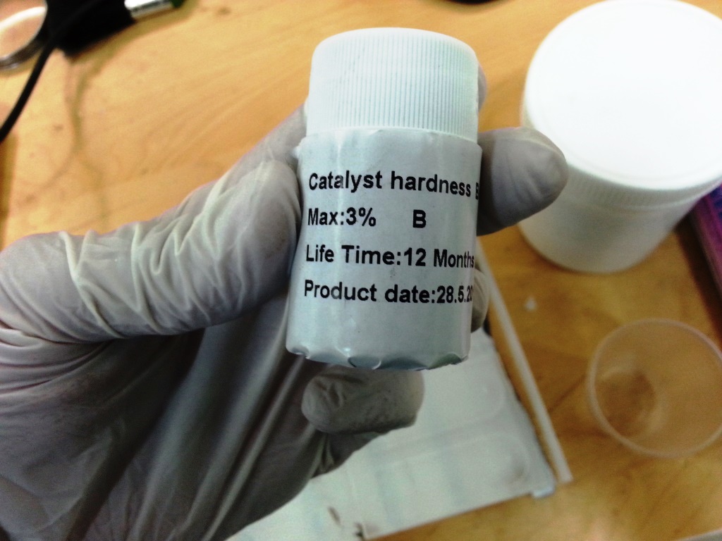
- For the EPOXY product I found a technical data sheet with linited safety instructions. The previous pre-cautions mentioned for silicon rubber applied as well for the EPOXY but in addition to that I found out the EPOXY : Hardner ration.
TOOLS AND MATERIAL USED (BOM):
STEPS PERFORMED:
MOULD DESIGN
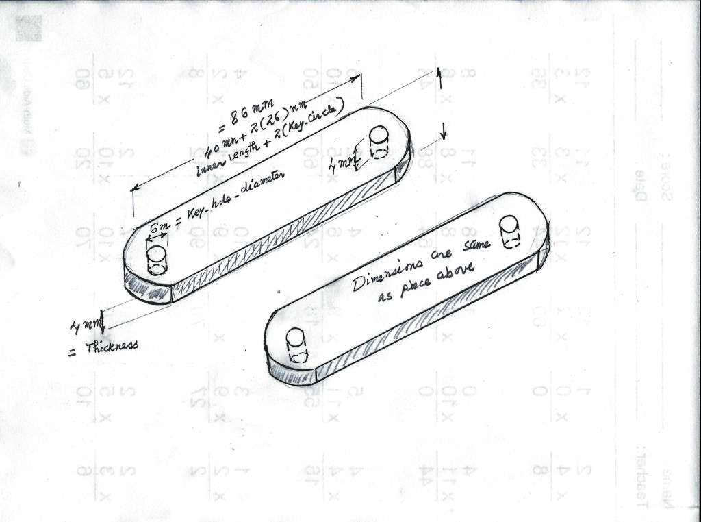
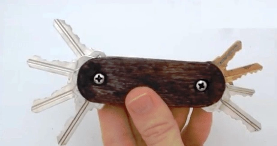
- I wanted to create a smart key chain and I started sketching the design on paper as shown below.
- I also looked up the typical dimensions of a key and I added the dimensions to my sketch as below.
- I decided to create my design using Autodesk Fusion 360. If you do not have Autodesk Fusion 360 you can download it from THIS LINK and install it.
- Open Autodesk Fusion 360 and create a new project. To make my design parametric, I started by creating my parameters
- I created a new sketch where I started to draw one side of the smart key chain
- I extruded the side to thickness of 4mm.Then I duplicated the side to have 2sides.

- I exported the design as STL file.
MILLING THE MOULD
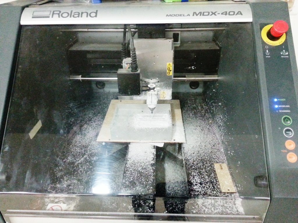
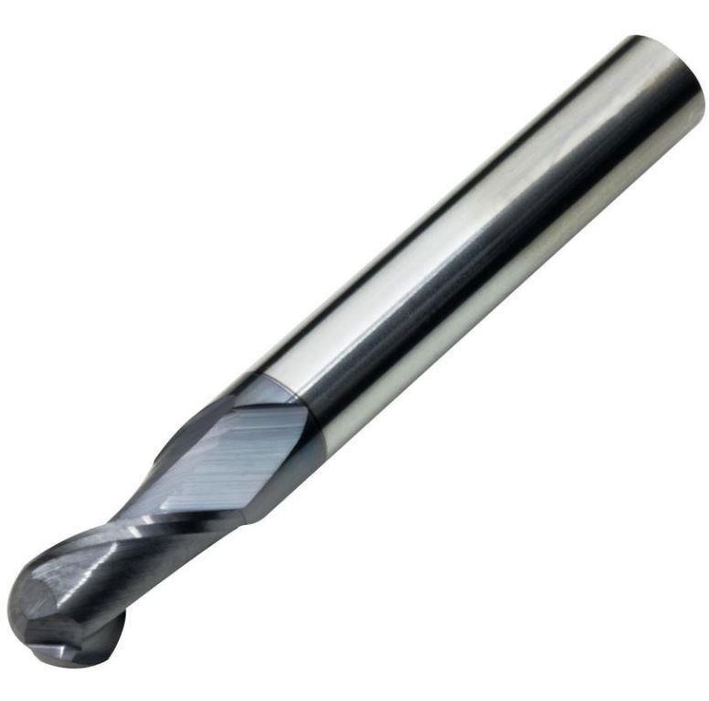
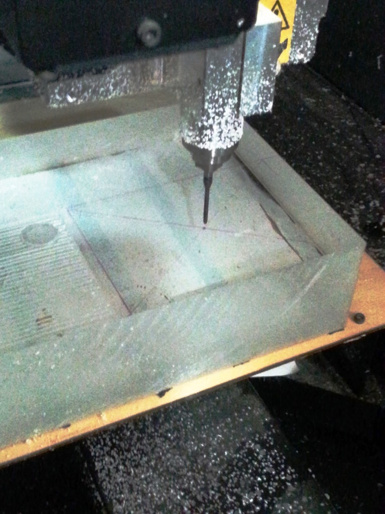
- For milling the POSITIVE part of the mould, we used: The Roland Modela MDX-40 A, a 4mm ball-nose end mill and Acrylic
- We did draw with a permenant pen a box with the same dimensions of the model we want to mould and created diagonals as shown in the photos where the point of intersection should be the origin (i.e: Center point)
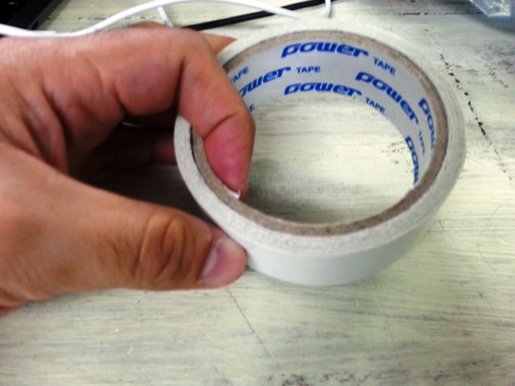
- We added double-tape to the acrylic piece and we fixed it to the modela bed.
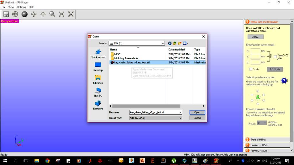
- We opened the SRP player and imported the .STL file we saved earlier, If you are not familiar with the SRP player then go through the tutorial in THIS LINK. I found it very useful.
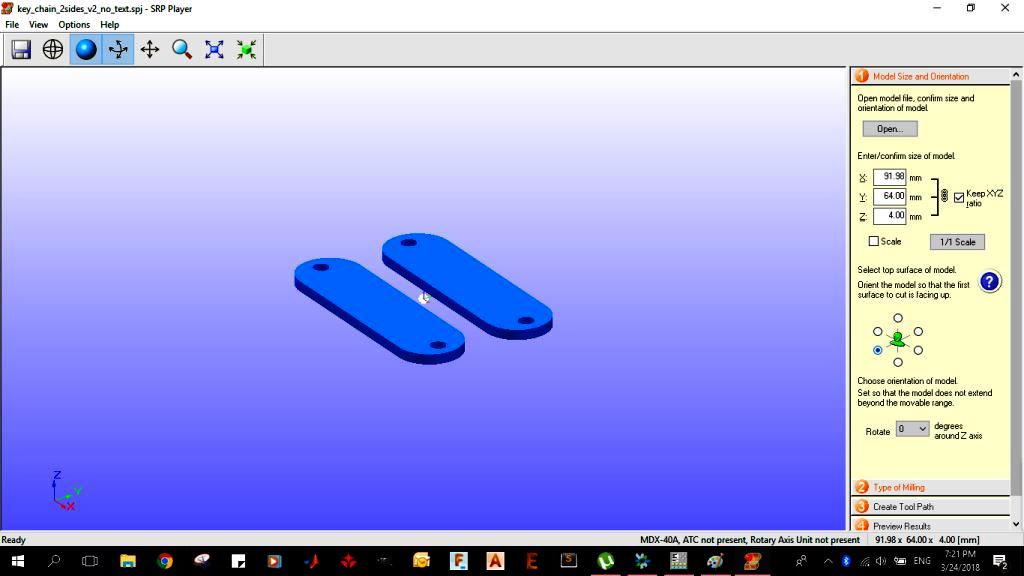
- I set following in the SRP player:
- set the dimensions / size of the model to: X = 98.98mm, Y = 64mm, Z = 4mm.
- Adjust the orientation to be easy to drill.
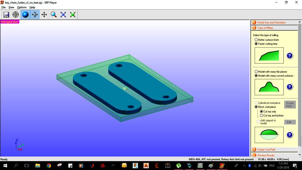
- Type of milling: "Faster Milling Time"
- Choose "Model With Many Curved Surfaces"
- Set Block workpiece: "Cut Top Only"
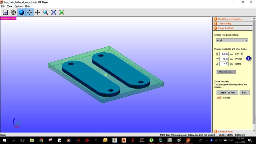
- Set the workpiece dimensions to: X= 106 mm, Y= 78 mm, Z= 4.5 mm.
- Create ToolPath.
IMPORTANT TIP!:
To save time although the Acrylic piece dimensions were large and its thickness was definitely larger than 4.5 mm, we did enter the dimensions of the working piece slightly larger than the model dimensions so that the Modela does not do extra work that is not really needed.
To save time although the Acrylic piece dimensions were large and its thickness was definitely larger than 4.5 mm, we did enter the dimensions of the working piece slightly larger than the model dimensions so that the Modela does not do extra work that is not really needed.
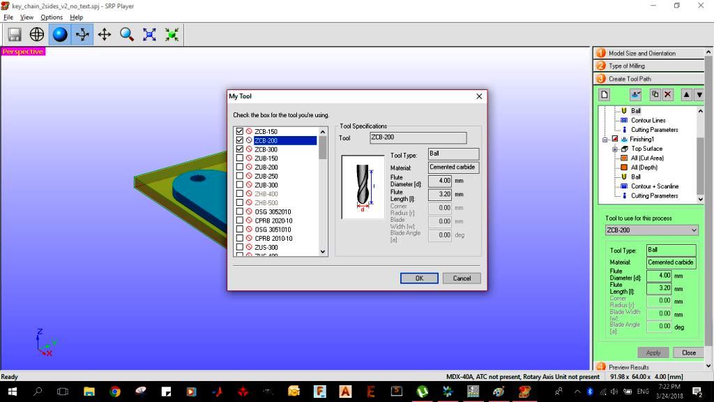
- Under Toolpath section: Choose the ZCB-200 Tool which is a 4mm diameter ball-nose mill.
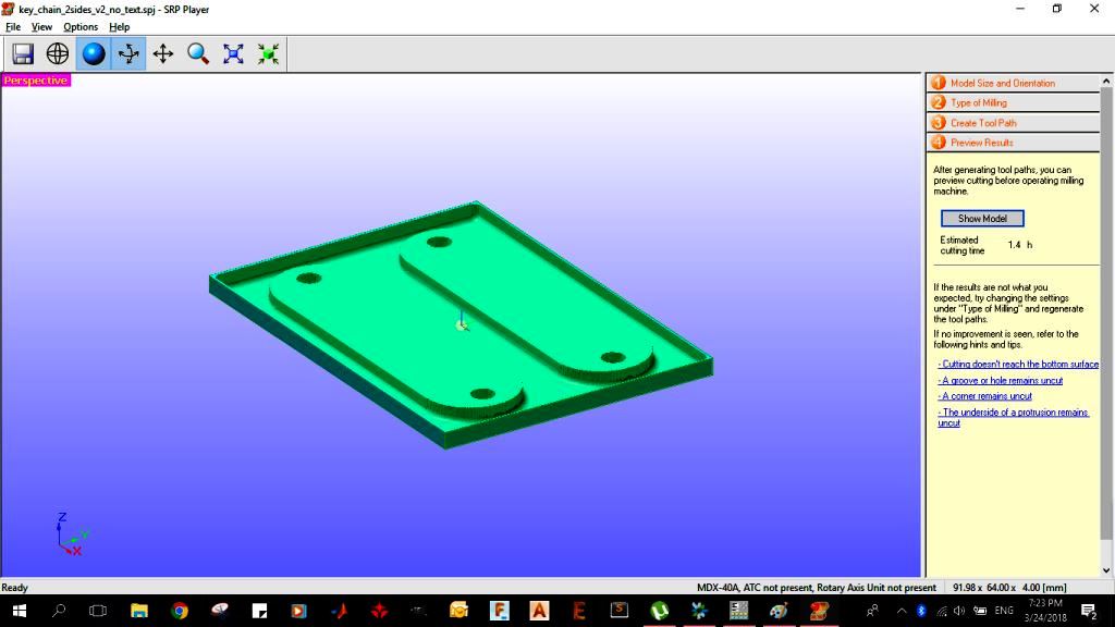
- I then previewed the results and the estimated time was 1.4 hours.
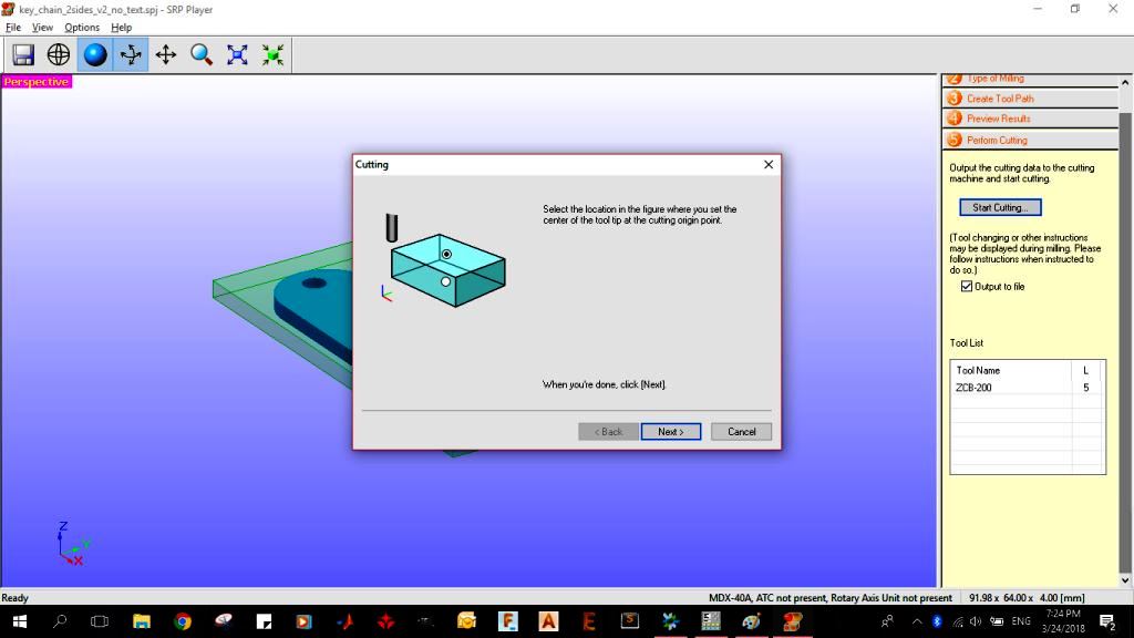
- I chose the location to set the center of the tool tip to be in the center as shown below.
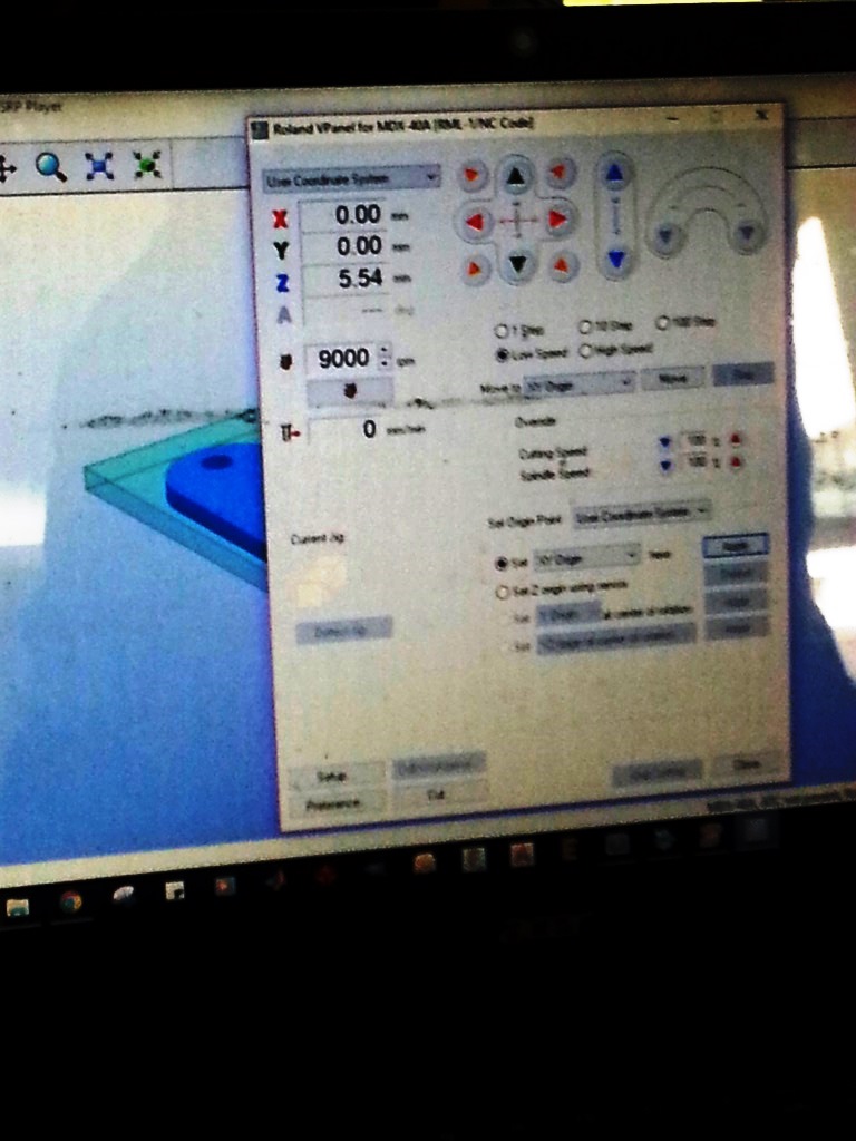
- From the VPANEL software, we moved the end mill using the arrows to reach the desired X0, Y0 position and then we adjusted teh Z0 automatically using the sensor.
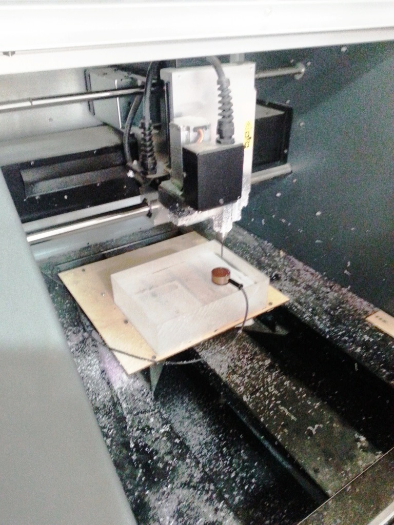
- Finally we started the milling process.
ISSUE WE FACED AND HOW IT WAS RESOLVED?
In the beginning we got "Machining Error" and the Modela stopped un-expectedly. it did stop in different locations and with different models. We tried to run the SRP player on another laptop thinking that it might be a problem with the PC but it again did the same!!. We tried another USB cable and it worked
In the beginning we got "Machining Error" and the Modela stopped un-expectedly. it did stop in different locations and with different models. We tried to run the SRP player on another laptop thinking that it might be a problem with the PC but it again did the same!!. We tried another USB cable and it worked
CASTING THE MOULD
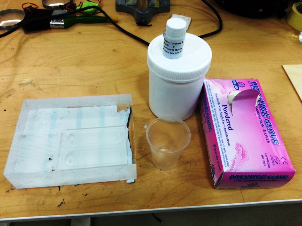
- We used Silicon Rubber for the casting of the mould, now prepare all the material and tools you need (i.e: Silicon Rubber, hardner, pair of gloves, something to steer with, a plastic cup and the Acrylic milled mould)
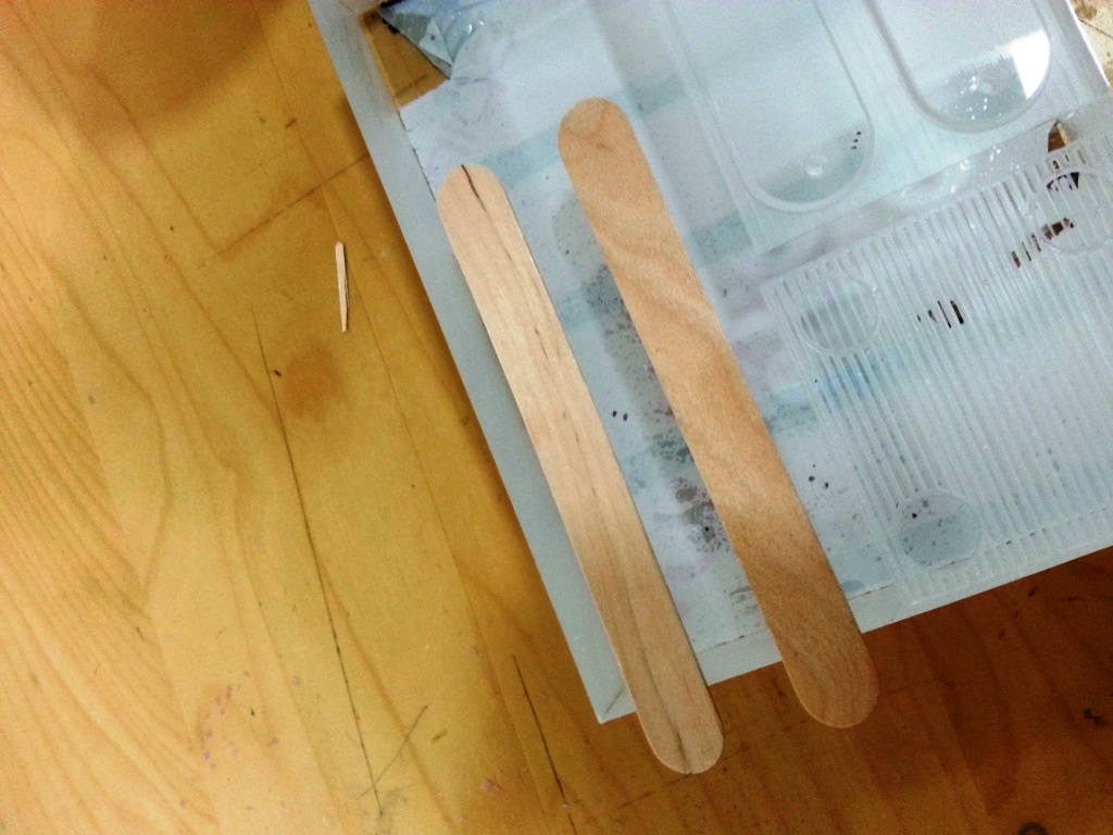
- Pour some (quantity that is enought to fill your mould) of the silicon rubber in the plastic cup
- Add half the cap of the hardner bottle to the silicon rubber, Steer Gently to remove all the bubbles.
- Start Pouring the mixture to fill the mould, Pour from above and try to make the poured beam as thin as possible to minimize the bubbles.
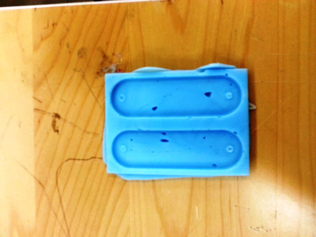
- I left it for 2 hours to dry then I started to detach the silicon rubber mould carefully and gently from the acrylic.
CASTING THE FINAL MODEL
- For casting the final model I used the EPOXY and similar to the previous process I prepared all the material and tools needed (i.e: Epoxy, hardner, pair of gloves, something to steer with, a plastic cup and the created silicon rubber mould)
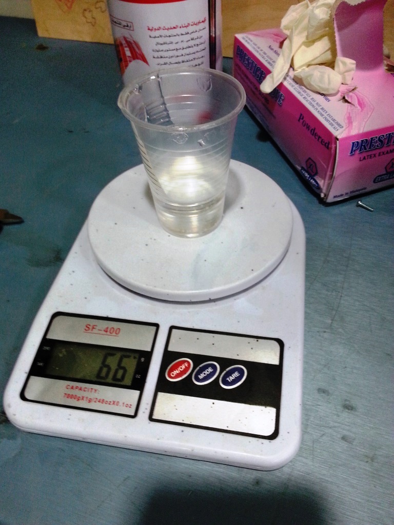
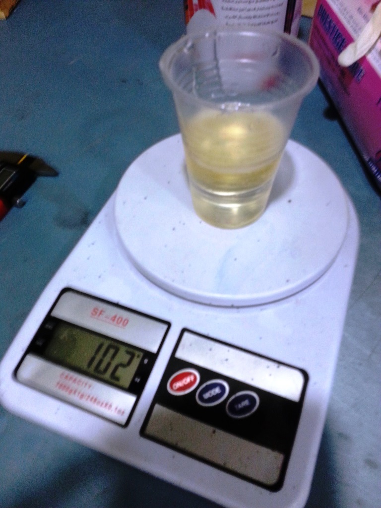
- I created a mixture with the ratio of 2 (EPOXY) : 1 (HARDNER). I used a scale to ensure I am adding accurate volumes.
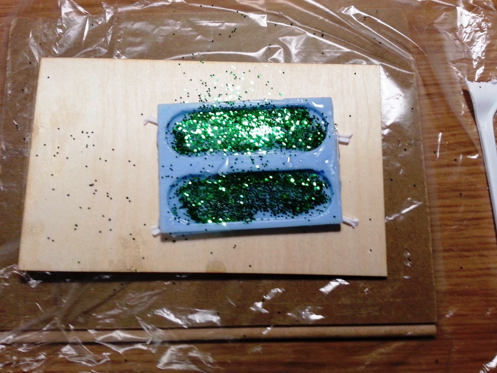
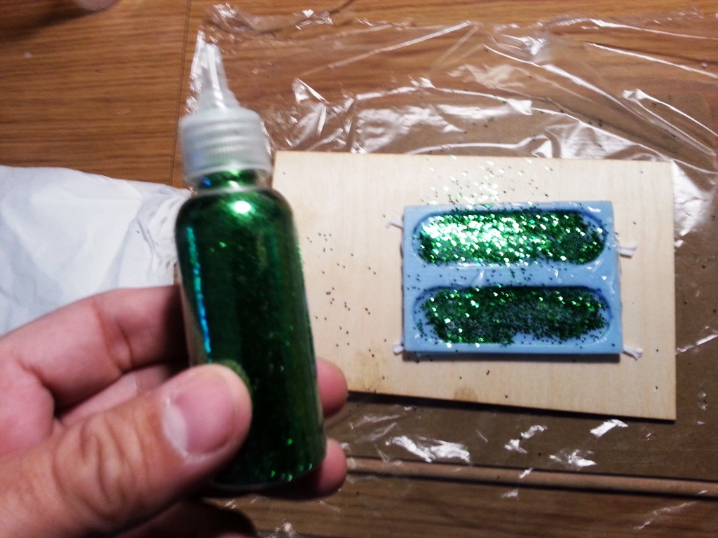
- I closed holes in the silicon rubber with silicon, then I added glitter in the bed of the mould to give it a shiny look
- I poured the mixture and then I again added glitter to the top
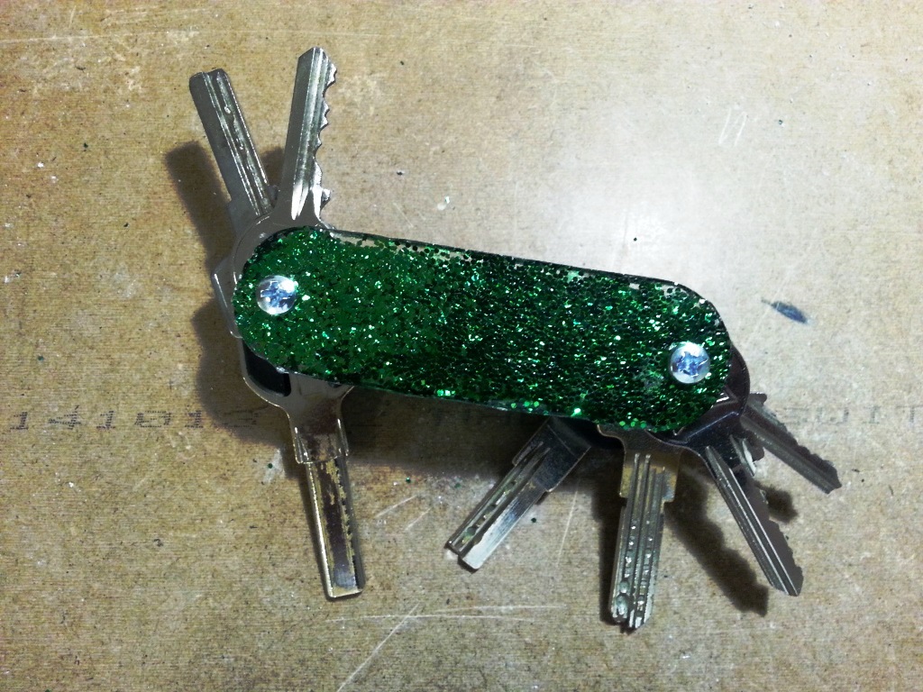
- I left it overnight and here is the final result.
Files: