WEEK 6 - 3D SCANNING AND PRINTING
INTRODUCTION
This week I learned a lot about 3D printing and Scanning. It was really fun and challenging. It took me a lot of time to decide what can be done by additive and not subtractive, specially that I heard that the 5-axis CNC machines can almost create any geometric shape.
Assignment Description
Group Assignment:
- Test the design rules for your printer(s).
- Design and 3D print an object (small, few cm) that could not be made subtractively
- 3D scan an object (and optionally print it)
Learning Outcomes
- Identify the advantages and limitations of 3D printing and scanning technology.
- Apply design methods and production processes to show your understanding.
Have you (Checklist)
- ✔ Described what you learned by testing the 3D printers
- ✔ Shown how you designed and made your object and explained why it could not be made subtractively
- ✔ Scanned an object.
- ✔ Outlined problems and how you fixed them.
- ✔ Included your design files and ‘hero shot’ photos of the scan and the final object.
GROUP ASSIGNMENT
- One of the most annoying things about 3D printers is the fact that no two machines are made exactly alike. Although the parts may all be the same — but the calibration and alignment of these vital parts can be off by just a fraction of a millimeter, and in turn cause issues with prints.
- To test if the printer lives up to its claimed specifications, we printes the 3D Printing test object in THIS LINK which consists of a number of different tests, each designed to quantify and approximate the printer’s performance from a different angle.
- It’s got flat surfaces, curved surfaces, overhangs, fine details, and a whole lot more. If the printer isn’t good at something, this shape will highlight it.
- This test included:
- size: the object is 4x50x50mm (baseplate).
- hole size: 3 holes (3/4/5mm).
- Nut size: M4 Nut should fit perfectly
- fine details: pyramide, cone, all numbers
- rounded print: wave, half sphere
- minimum distance between walls: 0.1/0.2/0.3/0.4/0.5mm
- overhang: 25°/30°/35°/40°/45°
- bridge print: 2/3/4/5/6/7/8/9mm
- surface: all the flat parts
- We downloaded the 3D Test STL File
- I downloaded the MakerBot Print software from HERE and installed it.
- I added the REPLICATOR2 printer to the MakerBot Software as shown below, I then created a new project and imported my STL file.
- We opened Settings and chose custom settings and added the recommended configurations as per the test file provider as follows:
- infill: 33% infill.
- layerheight: choose the smallest possible layerheight. optimal 0.1mm or lower.
- printer should run between 60-200mm/s
- We performed a print preview to identify the estimated time and see animation of the printed layers.
- We exported the file to MakerBot format and then copied the file to the printer SD card to print.

- In the printer panel, load the file from the SD and start printing.
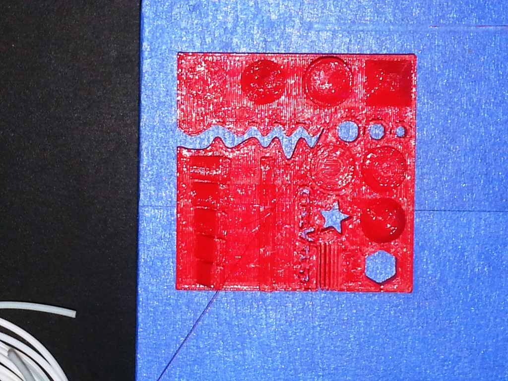
- The resulting object is as shown below:
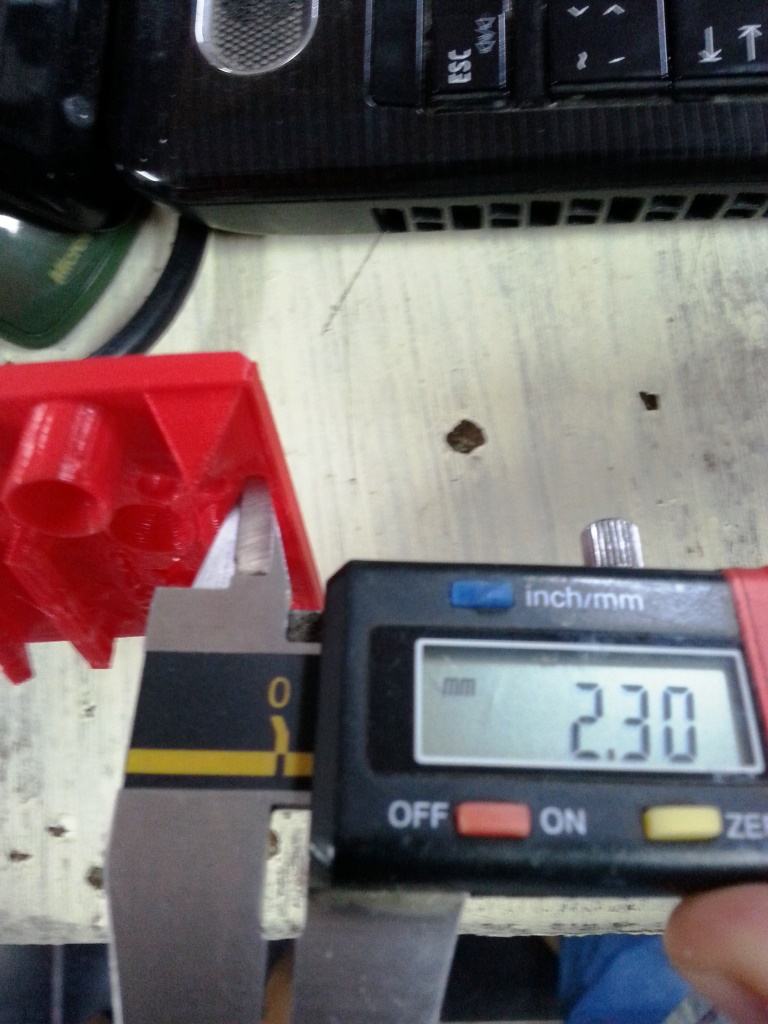
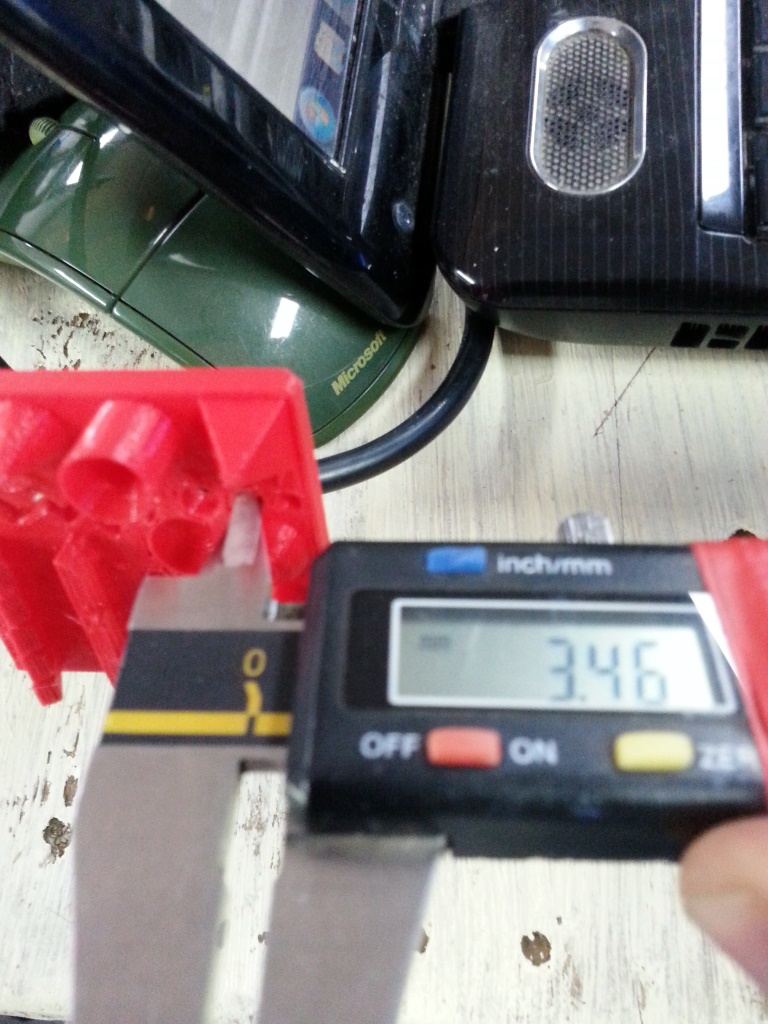
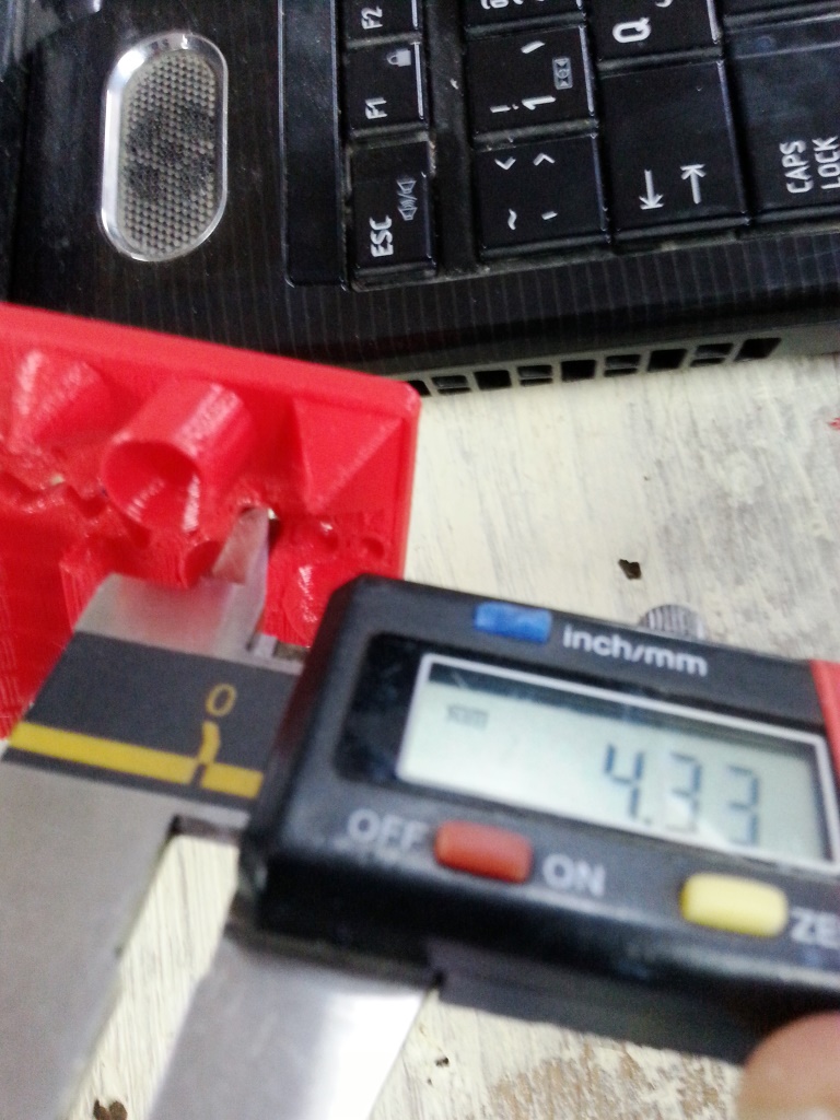
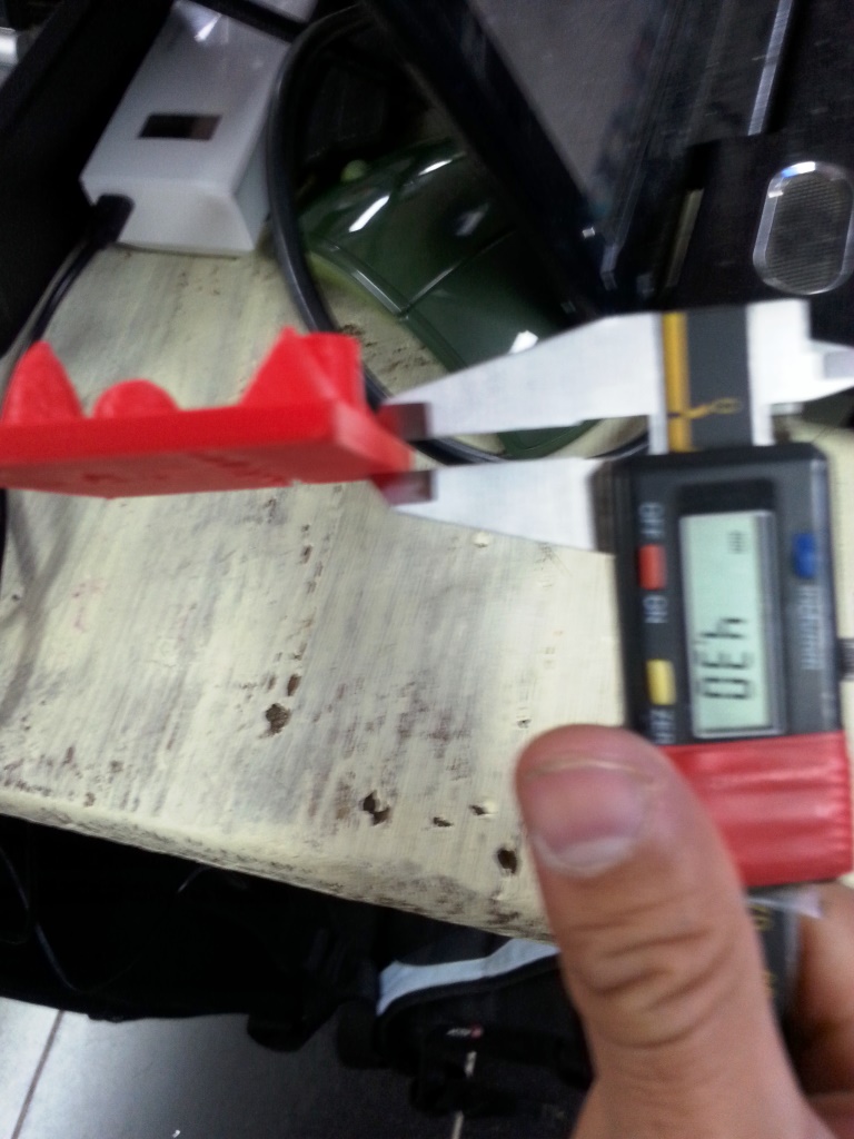
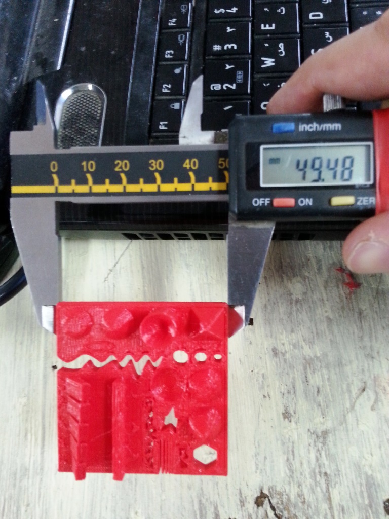
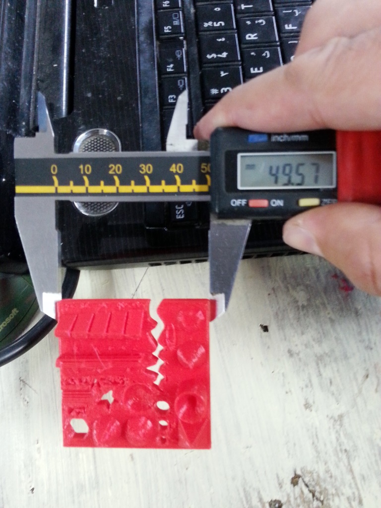
- From the test list, I was assigned the measuring of the object, holes and M4 bolt to see how accurate the physical model is in comparison to the digital one.
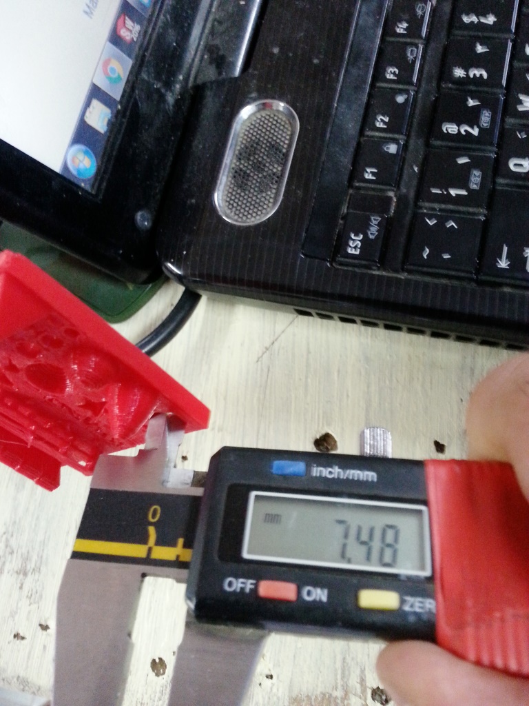
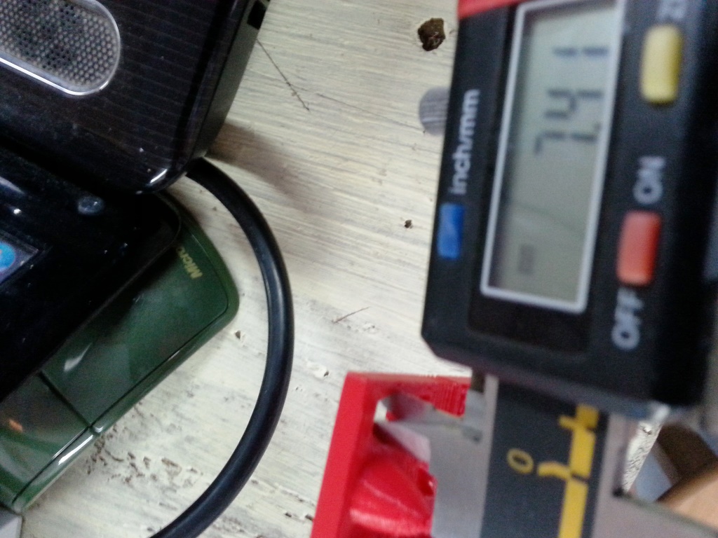
- The measurement results were as follows:
- The object physical measurements were:49.57mm x 49.48mm x 4.30mm compared to digital measurements (50mm x 50mm x4 mm)
- hole size: 3 holes (2.30/3.46/4.33 mm) compared to digital measurements (3/4/5 mm).
- Nut size: was 7.4mm compared to digital measurements 7mm
FINDINGS FROM THE TEST RESULTS:
I looked up the results I found on the internet and most the sites stated that if the measurement I get are consistently different than the actuals then this indicates that the nozzle of the 3D printer is wearing out and getting an opening that is changed from the factory measurment.
I looked up the results I found on the internet and most the sites stated that if the measurement I get are consistently different than the actuals then this indicates that the nozzle of the 3D printer is wearing out and getting an opening that is changed from the factory measurment.
INDIVIDUAL ASSIGNMENT (3D PRINTING)
- The 3D printing individual assignment was to design and 3D print an object (small, few cm) that could not be made subtractively. The challenging part was to identify what are the conditions that can make an un-object impossible to be created subtractively. After some research I found the following 3 criteria in A BOOK named "Additive Manufacturing Technologies" as follows:
- High Accuracy and Complexity: Where the object size o level of details can not be created because the CNC bit size is not small enough or the material can not simply be cut to that level of accuracy.
- Geometry: Where the drilling tool can not reach the surface because of physical blockage (Example: Object inside an object)
- I decided to use the second criteria nad create an object inside an object. I used autodesk fusion 360 to create my object.
- I opened Autodesk fusion 360, I created parameters to ensure my design is parametric.
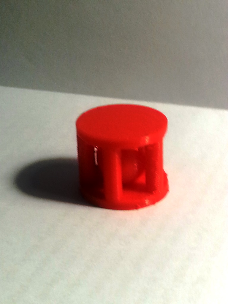
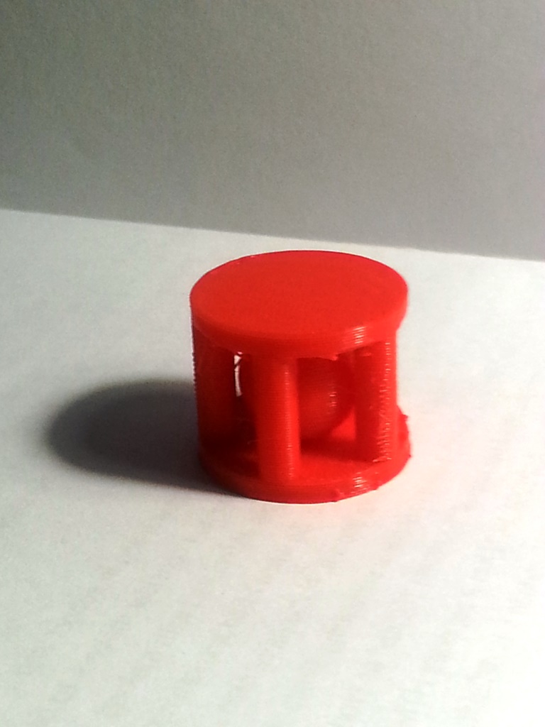
- I sketched a circular base and extruded it, I extruded 5 pillars out of the base and then I duplicated the base to create a top.
- Finally I create a sphere inside the earlier created object.
- To export STL file, I clicked on MAKE from the top bar, chose 3D print and in the resulting dialogue box I selected the object and clicked OK.
- Now open the MakerBot Print software, create a new project and insert the STL file you exported.
- From the side bar go to settings and click on custom settings button.
- I changed the default settings to the following settings to tweak my print:
- Layer Height = 0.3mm
- Infill Density = 15%
- Travel Speed 110 mm/s
- Filament Diameter = 1.75 mm
- Copy the exported file to the printer SD card.
- From the printer panel load the file to print from the SD card and start printing.
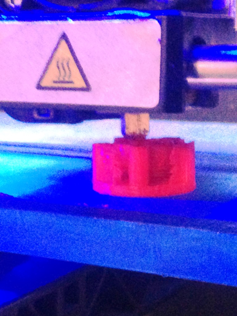
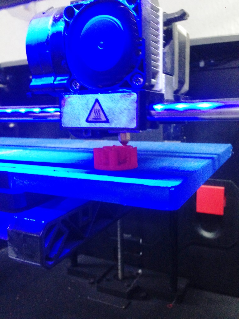
- I finally started to remove the supporting material using PCB tools.
- Here we are.
INDIVIDUAL ASSIGNMENT (3D SCANNING)
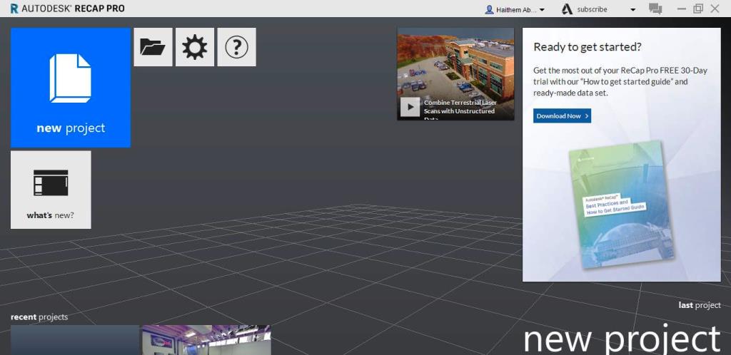
- The 3D Scanning (individual assignment) was to scan and optionally 3D print an object, I chose to use the Autodesk Recap Pro that can be downloaded for free under student version from HERE .
- Initially the 3D scanned model was not showing all the object details and had a lot of black gaps, that was resolved by simply taking more photos in different locations.
- The accuracy was increased by adding a floor surface for hte object that has a texture because that helped the software to get the texture points as a reference points and accordingly draw a better grid for the scanned object.
- I decided put my object in a scene with the following arrangement for better results:
- Good lighting and illunination in all sides of the object.
- Background with different color than the base / ground where the object is located.
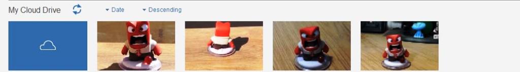
- I put the camera on the same level as the object and moved around the object while taking photos every 45 degrees and then I repeted the process with defferent elevations and different views till I took a total of 100 photos (this is the aximum that the RECAP Pro can take.
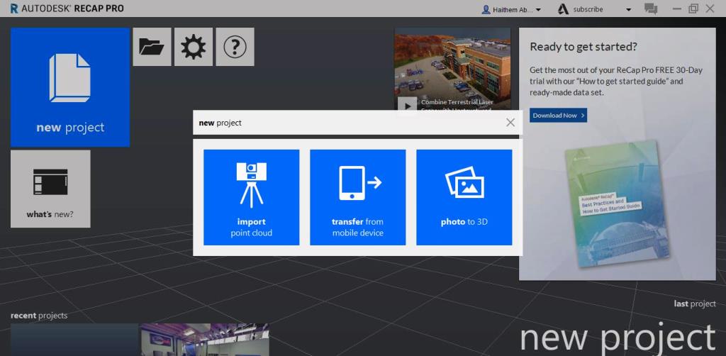
- I copied the photos to my Pc then I opened the recap pro and created a new project, I selected "PHOTO to 3D" where it launched the RECAP Photo program.
DIFFICULTIES FACED WHILE SCANNING:
I faced the following difficulties while doing the 3D scanning:
I faced the following difficulties while doing the 3D scanning:
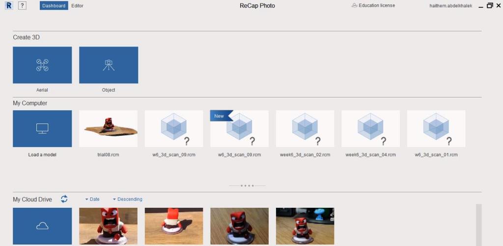
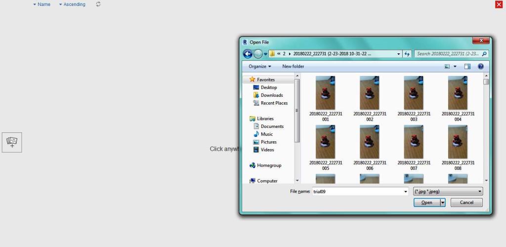
- I selected the OBJECT and browsed to the location where I copied my photos.
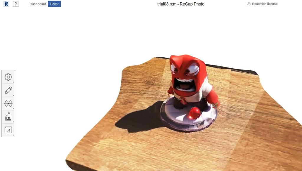
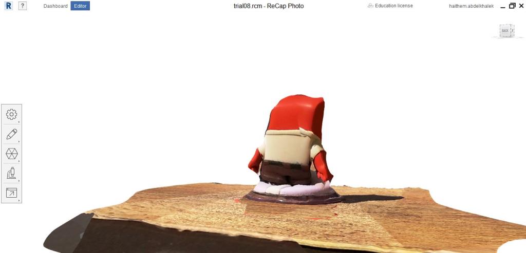
- The photos will be uploaded to the cloud and get processed, once done download the created model .RPM file to your PC.
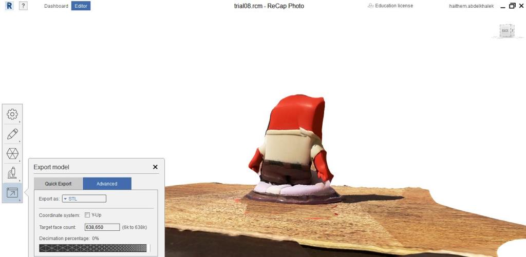
- I opened the .RPM file created and the results are as below. I did few corrections and editing then I exported to STL file to be ready for 3D printing.
Files: