WEEK 4 - COMPUTER-CONTROLLED CUTTING
INTRODUCTION
This week was very interesting as it is the first assignment where there is a real interaction with a machine (i.e: The Laser cutter and Vinyl Cutter). It was also challenging as when we hit the ground and try to implement the design and turn it to real tangible deliverable all the issues appears. It also included a group assignment and individual assignment. I will do my best to explain in this page all the steps that I performed as well as the issues that I faced.
Assignment Description
Laser Cutting
- characterize your lasercutter, making lasercutter test part(s), making test part(s) that vary cutting settings and dimensions[group project]
- design, make, and document a parametric
- Cut something on the vinyl cutter.
Learning Outcomes
Laser Cutting
- Demonstrate and describe parametric 2D modelling processes.
- Identify and explain processes involved in using the laser cutter.
- Develop, evaluate and construct the final prototype
- Identify and explain processes involved in using this machine.
- Design and create the final object.
Have you (Checklist)
Laser Cutting
- ✔ Explained how you parametrically designed your files?
- ✔ Shown how you made your press-fit construction kit?
- ✔ Shown how you will use what you learnt in your proposed final project?
- ✔ Included your design files and photos of your finished project?
- ✔ Explained how you drew your files?
- ✔ Shown how you made your vinyl project?
- ✔ Included your design files and photos of your finished project?
Extra Tasks Requested By Ohad:
- ✔ Identifying what materials can and can-not be used in a laser cutter.
- ✔ Create a LIVING-HINGE deliverable using plywood.
- ✔ Create a wood thickness calibration tool (COMB) to help identifying the KERF value.
STEPS PERFORMED:
The Laser Cutter (Know Your Machine!)
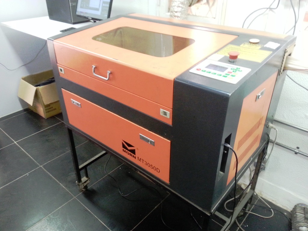
- The laser cutter we used in Fab Lab Egypt is the is MORN MT3050D. It's a 50/60 Watts CO2 laser machine with bed dimensions of 300 mm x 500 mm, it can cut through thickness of 1mm to 10 mm depending on the material.
- It is very important before operating on any machine to check the safety instructions, for this machine specifically, there are some warnings clearly viewed on a sticker on the machine.
- For more details about the machine check the official website HERE.
.jpg)
What are the safe / un-safe materials for laser cutting?
- Before proceeding with laser cutting it was important to identify what are the safe materials to laser cut and what materials are dangerous and should not be used for laser cutting.
- Safe Materials: Many wood, Plywood/Composite woods, MDF/Engineered woods, Paper, card stock, Cardboard, carton, Cork, Acrylic/Lucite/Plexiglas/PM, Delrin (POM), Kapton tape (Polyimide), Mylar, Solid Styrene, Depron foam, Gator foam, Cloth/felt/hemp/cotton, Leather/Suede, Magnetic Sheet, NON-CHLORINE-containing rubber, Teflon (PTFE), Carbon fiber mats/weave, Coroplast ('corrugated plastic').
- Un-Safe Materials: PVC (Poly Vinyl Chloride)/vinyl/pleather/artificial leather, ABS,HDPE/milk bottle plastic, PolyStyrene Foam, PolyPropylene Foam Catches fire, Epoxy, Fiberglass, Coated Carbon Fiber, Any foodstuff.
- I also found more interesting information about this subject in This Link and This Link .
Laser Cutter (Group Assignment)
- To know more about the approach to fufill the requirements of this assignment, I went through the work performed by different previous students and I found the work done by both May El Dardiry and Steven Chew very impressive and informative.
- The aim of this task is to determine the optimal power and speed settings for our laser cutter. accordingly I used our laser cutter on a 3mm plywood sheet. I read about the recommended settings by the provider and I used them to determine my testing range.
- I decided to draw 18 (20mm x 20mm) squares and tried different combinations of speed and power in order to determine the optimal settings for engraving and cutting the 3mm plywood board.
- I did draw the squares using Autodesk Fusion 360 and I saved the file as DXF file then I imported the file in coreldraw as it included an add-on for the laser cutter. I also started to add some text to clarify the used frequenct and power ranges used in the testing.
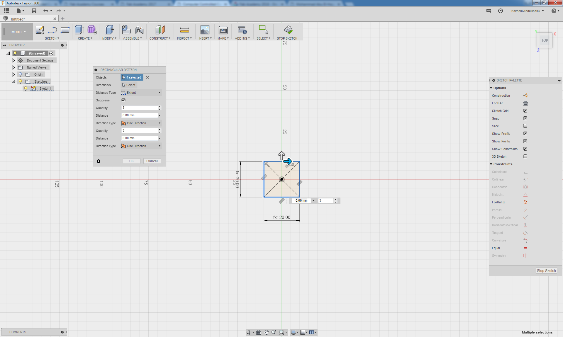
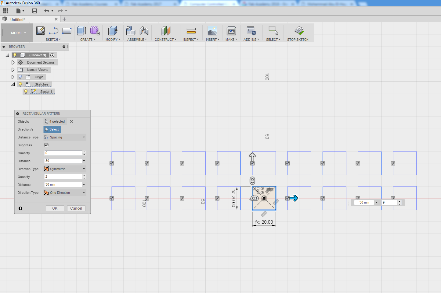

- To save the material we decided to resize the squares to 50% of the original size to be 10mm x 10mm.
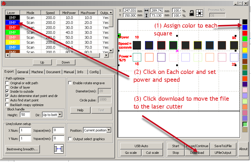
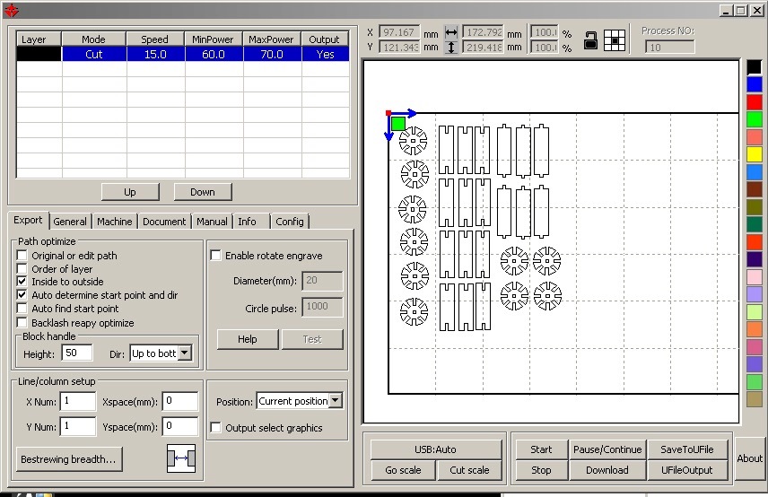
- I did click on the coreldraw laser cutter plug-in button and it moved me to the "laser work" software.
- For the first row of squares (Engraving test), We started to pick each square and assign to it a color from the righ hand panel, then by double clicking on the color we assigned speed of 200 and range of power (10% to 90%) .
- For the second row of squares (cutting test), Similarly we assigned power of 75% and range of speeds (15 to 23)
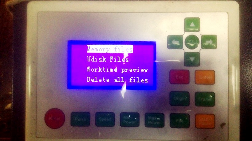
- We clicked on the DOWNLOAD button to send the file to the laser cutter and we saved it with a name we chose.
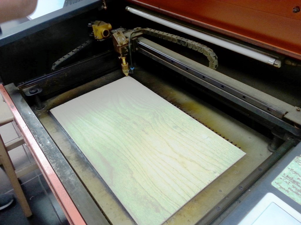
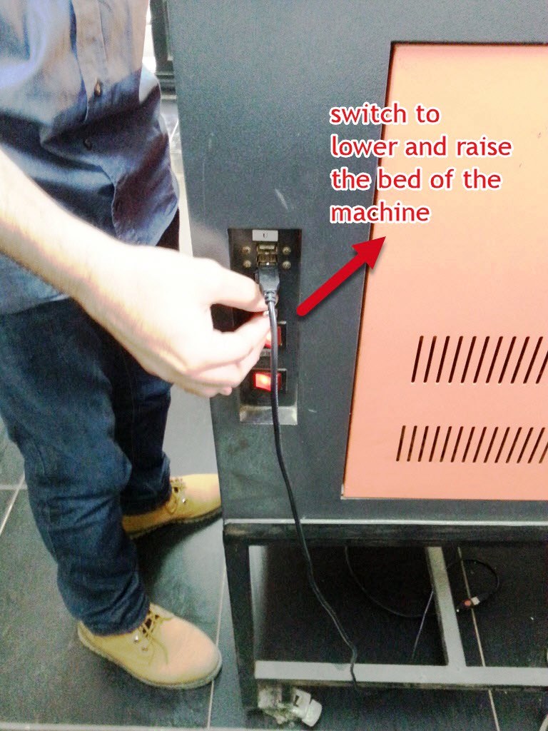
- We placed the plywood 300mm x 500mm sheet and tested the focus by adjusting the bed height to be 6mm from the laser lense, closed the cover.
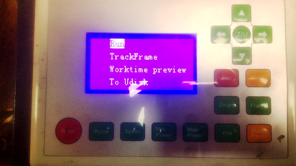
- From the panel we clicked on file button then in chose memory, select our file and finally chose run
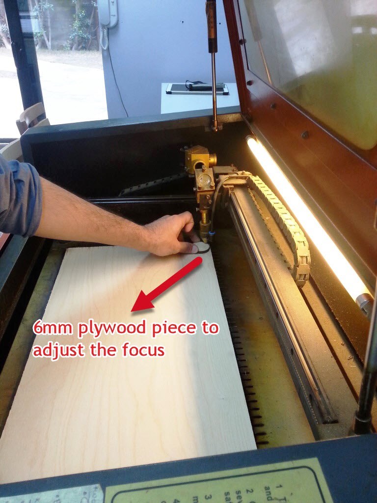
Tips From Regional Review! - It is more favored while adjusting the focus specially with organic materials like wood that can usually bend to adjust the focus from the center not the corner. In addition, we can add piece of bigger weight in our "not-to-cut area" to help the material to be more stable and avoid that bending issue..
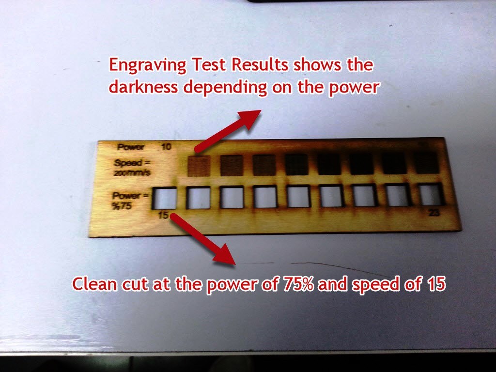
- From the resulting test map:
- For engraving we can pick the speed and power depending on the how dark we want the burning to be.
- For cutting it was clear that at POWER=75% and SPEED=15 the cut was clean and lowest burning for the edges.
Tips From Regional Review! - The minimum power is used to cut points (like corners), while max power is used along lines. It is noticed from the above photo that we are using too much power for "min" as if the corner of the test squaresare rounded. So we might need to lower the minimum power and for better test, we can use longer lines (i.e: bigger dimensions).
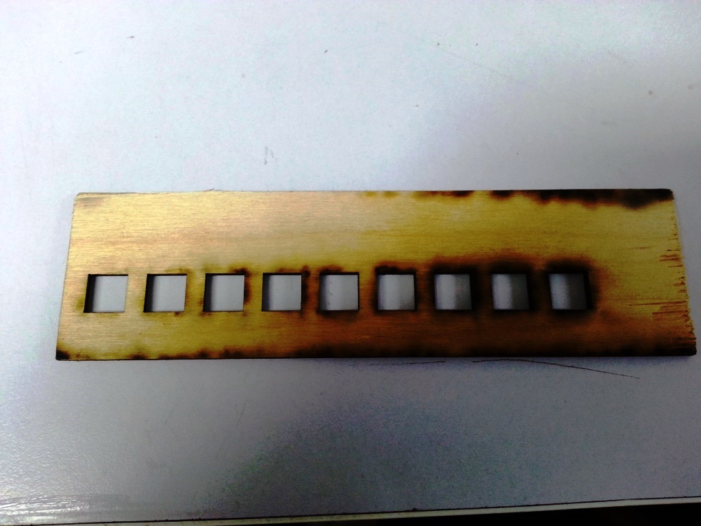
Tips From Regional Review! - It is noticed that the power used for cutting the test part might be high as so much burn is there. As a Recommendation power can be lowered and use tape at the back of the wood piece, it would get you much neat look.
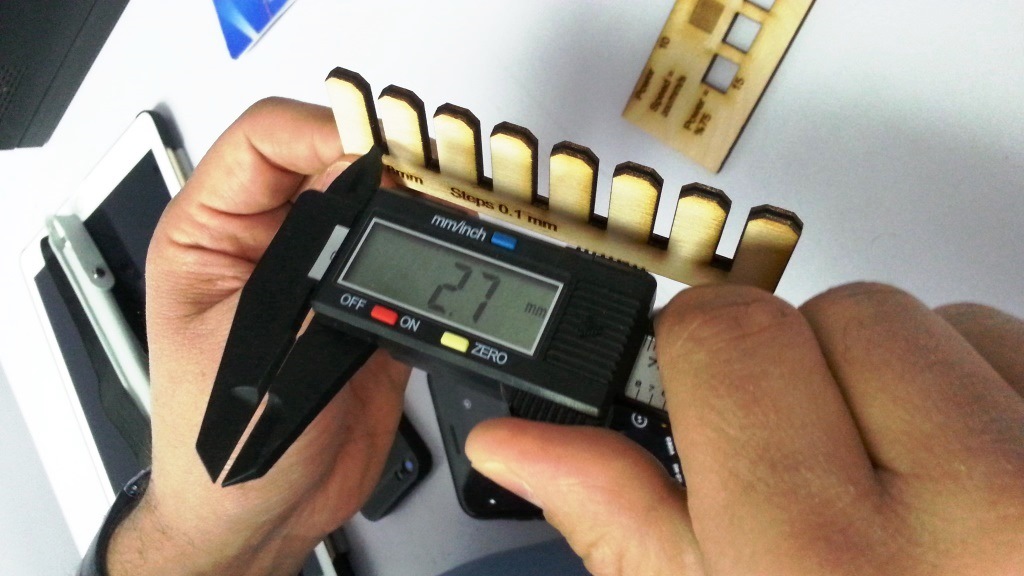
Notch Test Tool (The Comb)
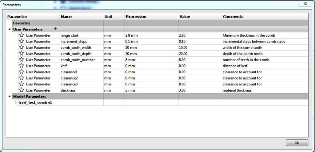
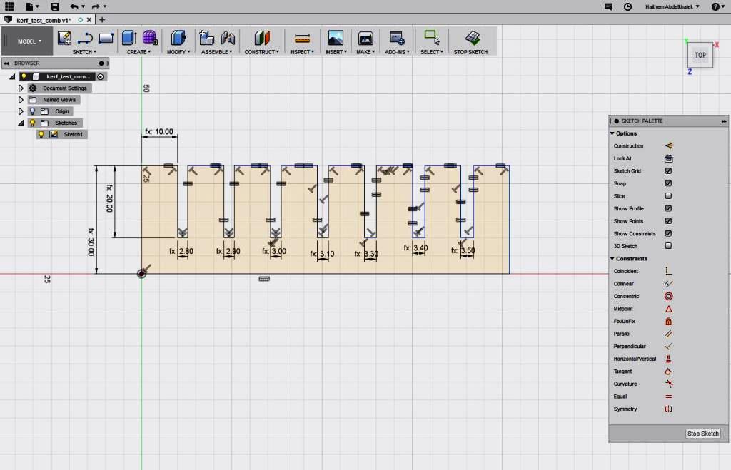
- Now I decided to create a tool to test the size of the notch / slot for a specific material thickness. Since the kerf we measured before is 0.1mm, for my 3mm plywood cardboard I decided to draw a series of chamfered notches ranging from 2.8mm to 3.5mm in 0.1mm increments.
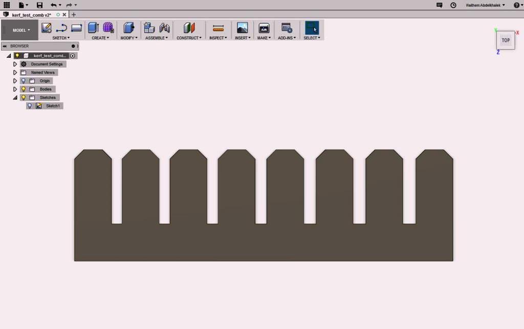
- I created a parametric design for my tool (The Comb) using Autodesk Fusion 360 as shown below.
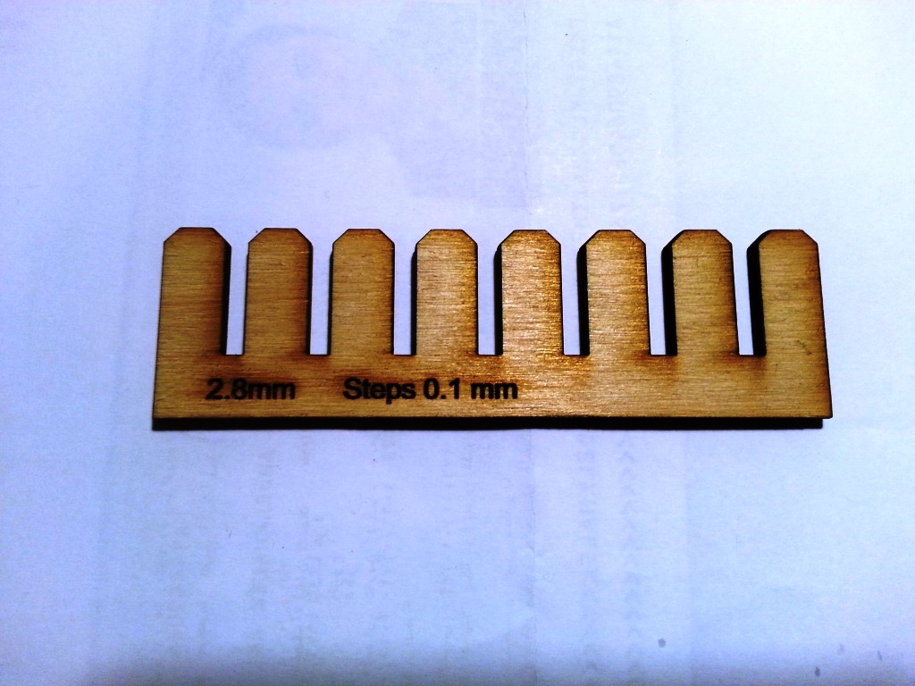
- We did try to fit the 3mm Thickness plywood board inside the notch and it did fit inside the notch marked 3.1mm. This is expected and it confirmed that the kerf we have is 0.1mm.
- We used the caliber to measure the width of each notch and it consistently showed that the width is less than the width in the design by 0.1mm which again is a proof that the kerf is 0.1mm.

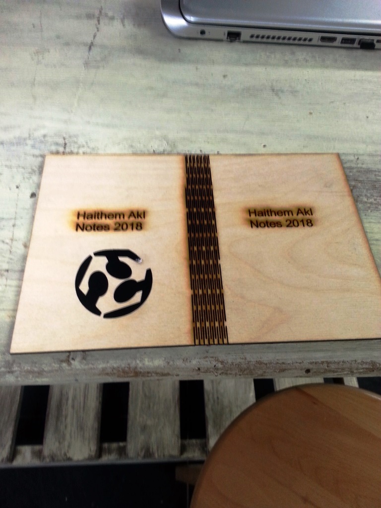
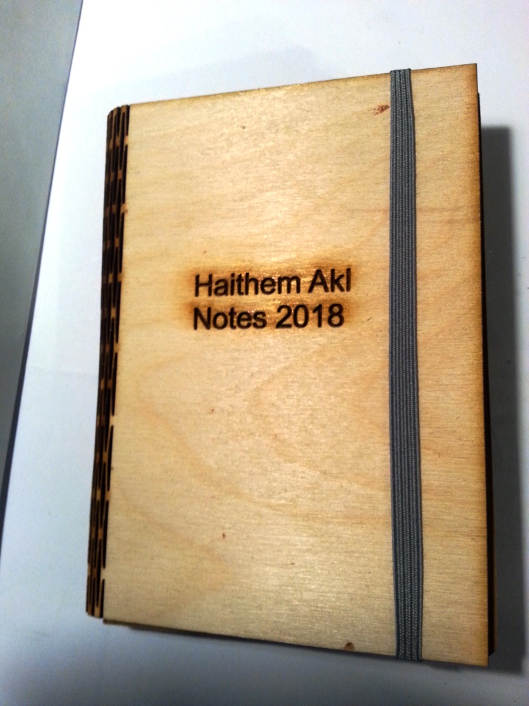
Living Hinge
- The idea of being able to creating curves and bend a sheet of wood is really attractive and fascinating and I was curious how it can be performed, So i was really happy when it was added to this week assignment tasks.
- I decided to create a book cover, so I measured the dimensions of the book cover and I found it to be 150mm x 110mm and the thickness is 15mm.
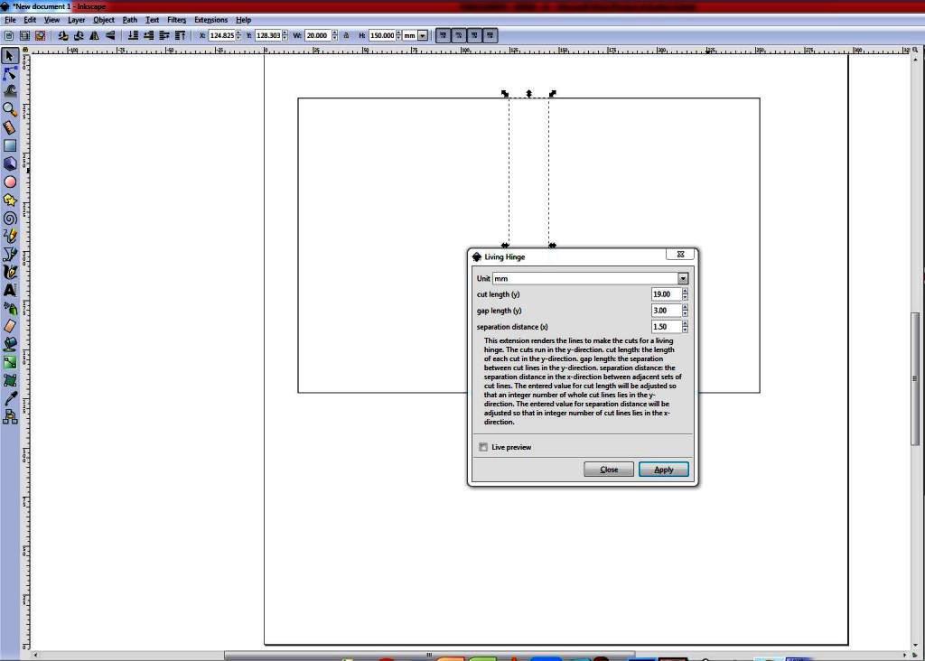
- I read about the Living hinge and I found that the patterns choice is controlled by the material and the tense needed. That was too much hassle for me to calculate so I downloaded the plug-In for Inkscape from HERE.
- I went through the steps in the tutorial stated HERE
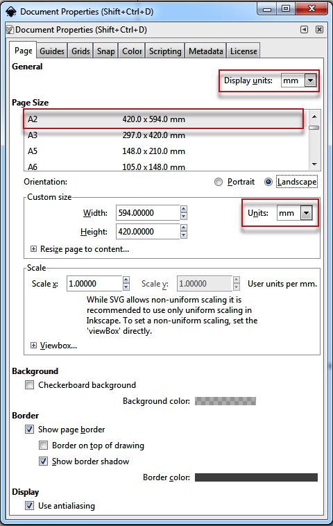
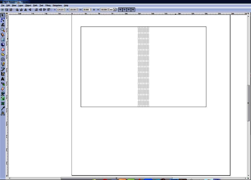
- I opened Inkscape, I did set the document properties to A3 and I did draw the book cover, then I applied the render to create the living hinge as shown below:
- I saved the file as DXF, Imported the file to corel draw and then to laser cut software to cut the book cover.
- Here are the end results
How did I apply COMPUTER-CONTROLLED CUTTING to my proposed final project?
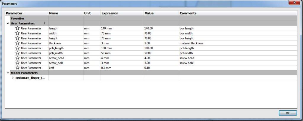
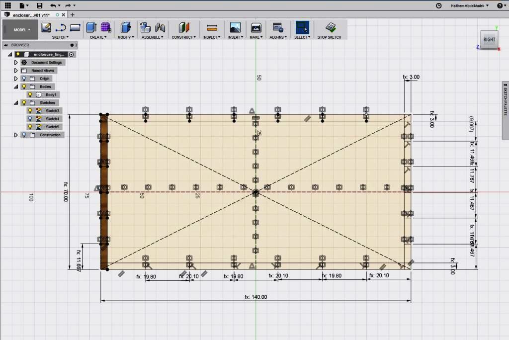
- In my proposed final project I wanted to create an enclosure for my IR transmitter and I stated in the previous week assignment that I would like to use 3mm plywood, more info about the design I used are available in Week3 Assignment Page located HERE.
- To ensure that I will not mess-up my Autodesk Fusion 360 design, I decided to copy my project and work on the copy.
- My original design was already parametric so I ONLY needed to add additional parameter for the kerf. I used different slot and finger width so for the "finger", I used a value of slot + kerf, since the laser cutter will burn away additional material. For the cutouts, I used a value of slot - kerf.
- I modified the dimensions in the 2D designs as shown below then exported the faces to DXF files.
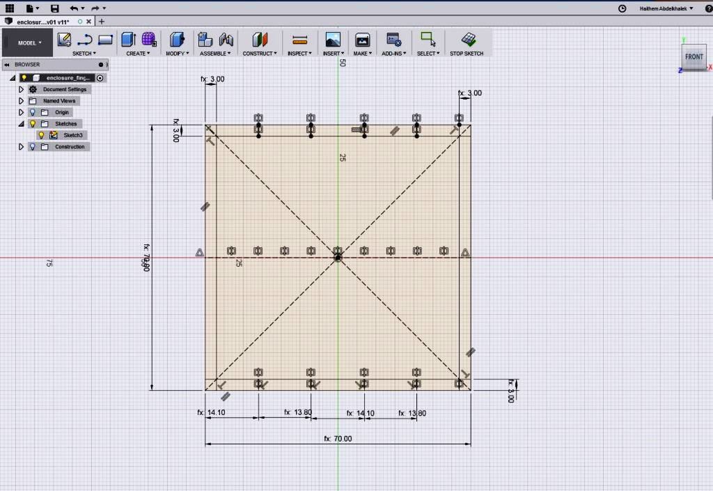
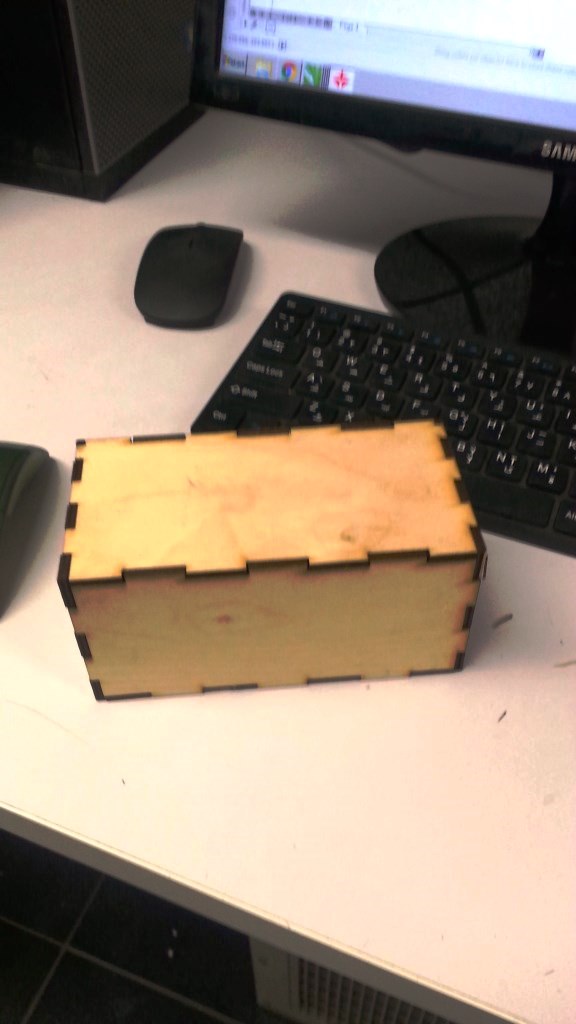
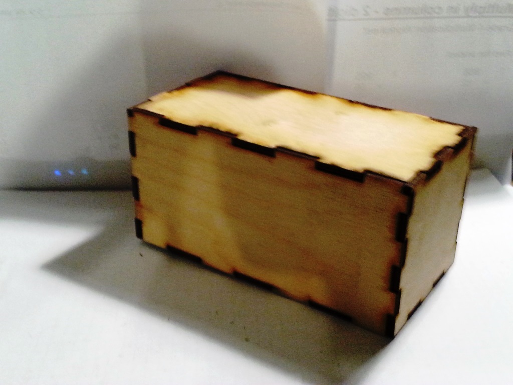
- I imported the DXF files to Corel Draw and then to Laser Cut software to cut it using the laser cutter
- The resulting box is as below:
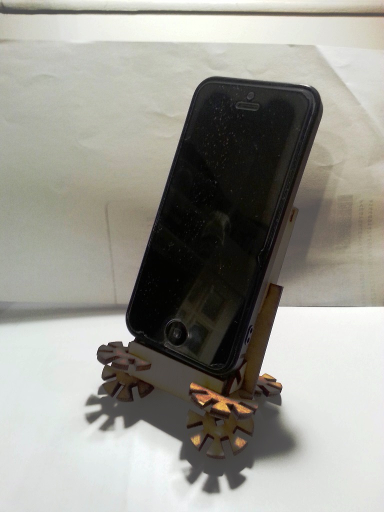
Construction Kit (Individual Assignment)
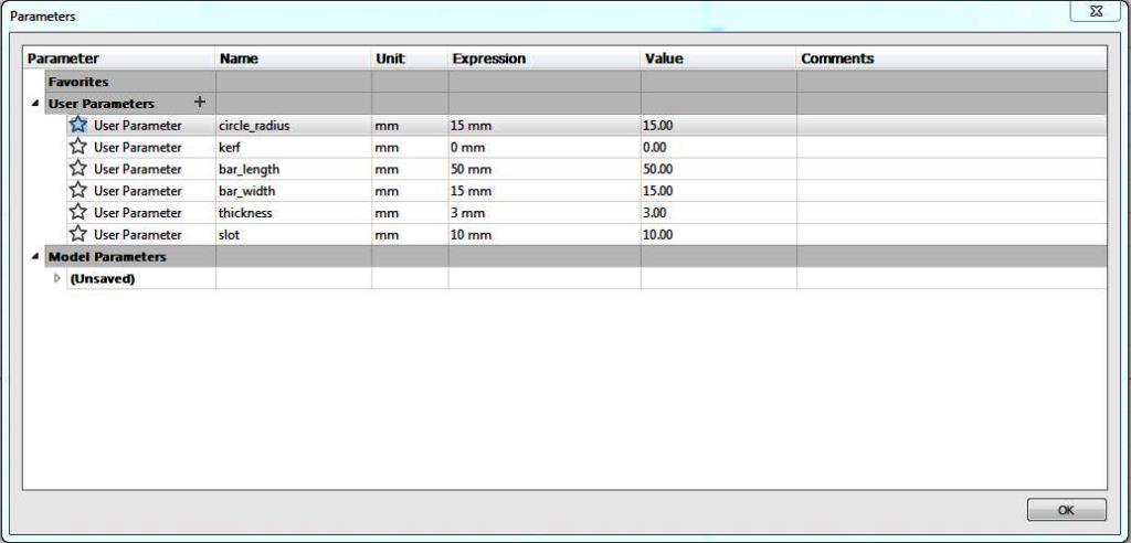
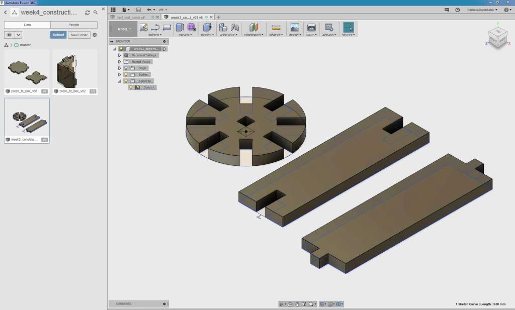
- I created my construction Kit from 3 Parts using Autodesk Fusion 360:
- A rectangular rod with a finger from both sides.
- A rectangular rod with a slot from both sides.
- A circle shape with 8 slots across 360 degrees (1 slots every 45 degrees)
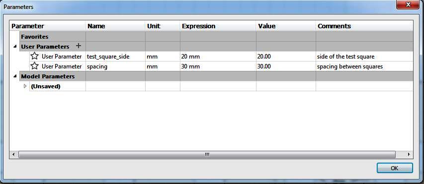
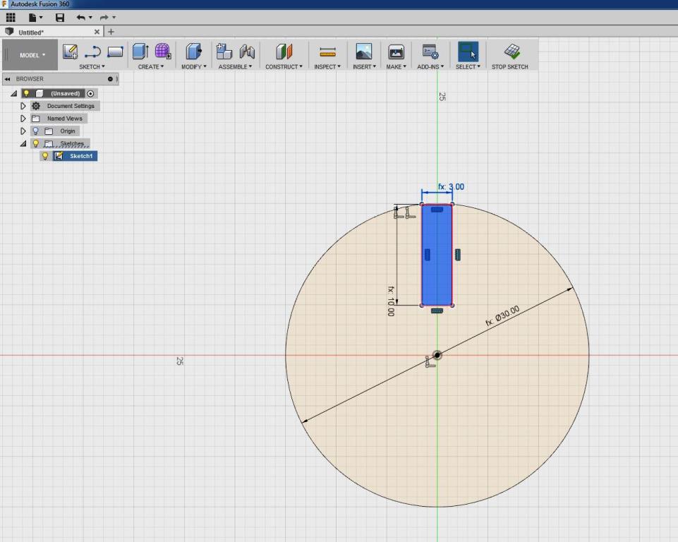
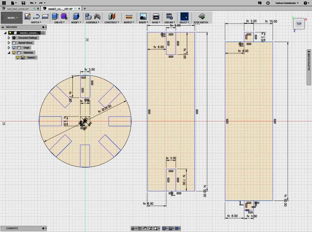
- I added my parameters to ensure my design is parametric as shown below:
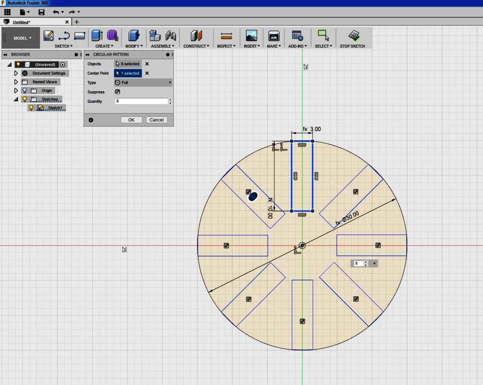
- I started by drawing the circular part: I added a slot depth with a little less than (Radius/2) to ensure that the parts will fit. I then created a circular pattern to create 8 slots.
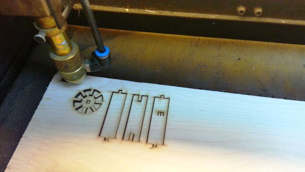
- I then created the 2 rectangular rods and extruded the 3 parts by 3mm Thickness.
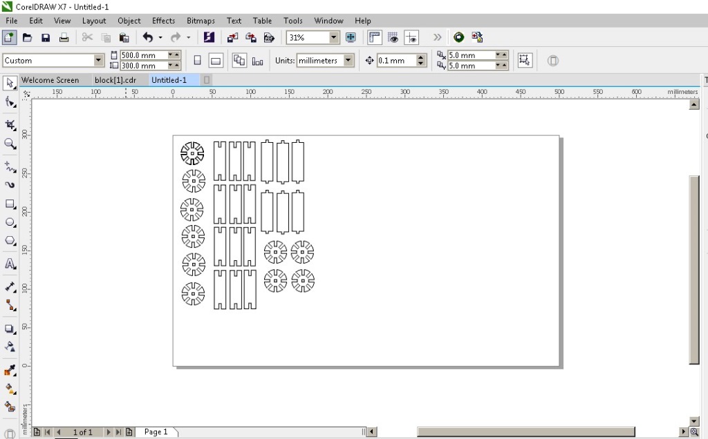
- I exported each of the parts 2D drawing to a separate DXF file and imported it to Corel Draw then to laser cut where I sent it to be cut.
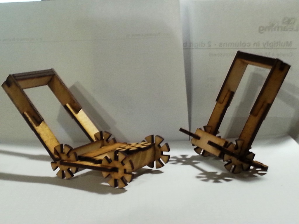
- The end result is as shown below:
Vinyl Cutting (Individual Assignment)
- I decided to cut the FAB ACADEMY logo to add it to the book cover I created earlier using the laser cutter, So the first step was to get the logo as a JPG.
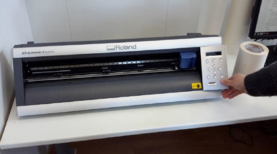
- In Fab Lab Egypt we are using a Roland GX-24 Vinyl cutter, more info about hte machine can be found HERE
- I went through the steps provided by THIS TUTORIAL and it was really helpful.
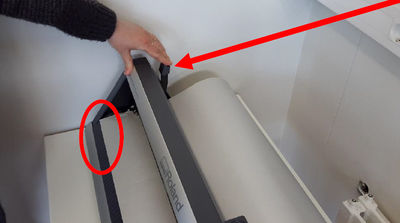
- Turn the machine on and feed the material through the slot. When you are feeding the material, make sure the lever is pushed away from the machine (so it's open).
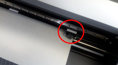
- The roll should be placed in the center of the machine. Position the 2 little wheels on both edges of the material. You can slide the wheels easily by pushing the metal plates on the back of the machine.
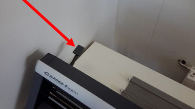
- Align the material with the wheels, then pull the lever toward you.
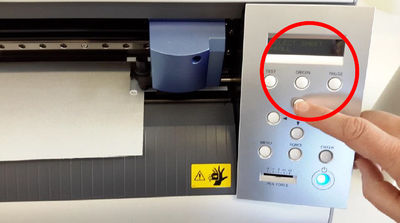
- In the menu display. Use the arrows to select [edge]. Which option you choose from the menu depends on what material you are loading.In my case I chose Piece.
- Roll is for setting up the starting point manually.
- Piece is for letting the machine measure all sides of your loaded sheet (like with smaller 'leftover' pieces)
- Edge is for letting the machine only find only 1 side of your loaded material. (when you just want to find the starting point at the edge of your material.)
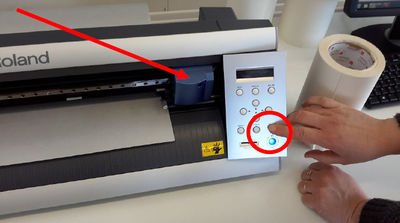
- To confirm, push the [enter] button. The machine will now start moving. The machine will pull on the material to find the edge. Now we are ready to push our design to be cut!
- The Roland vinyl cutter uses as software named "Roland Cut Studio", I tried to import DXF but surprisingly I discovered that it does not accept DXF and instead it accept normal JPG file.
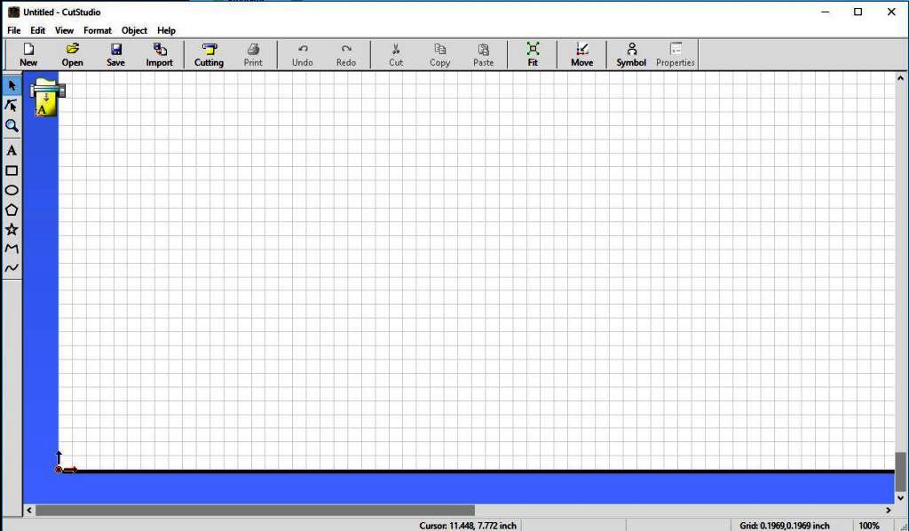
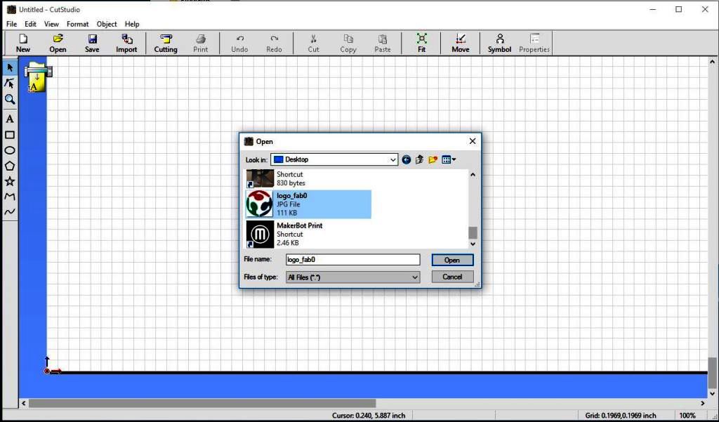
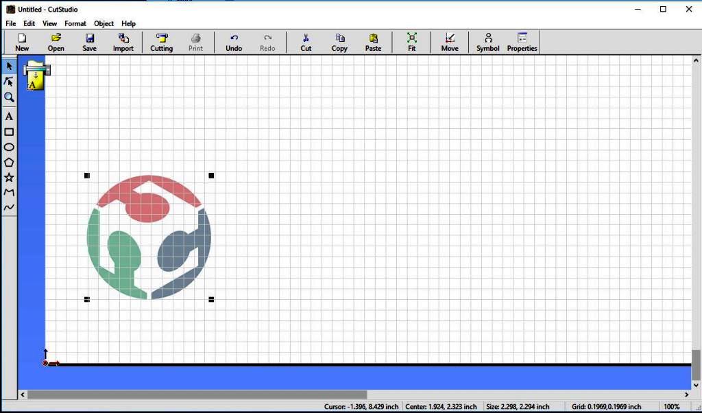
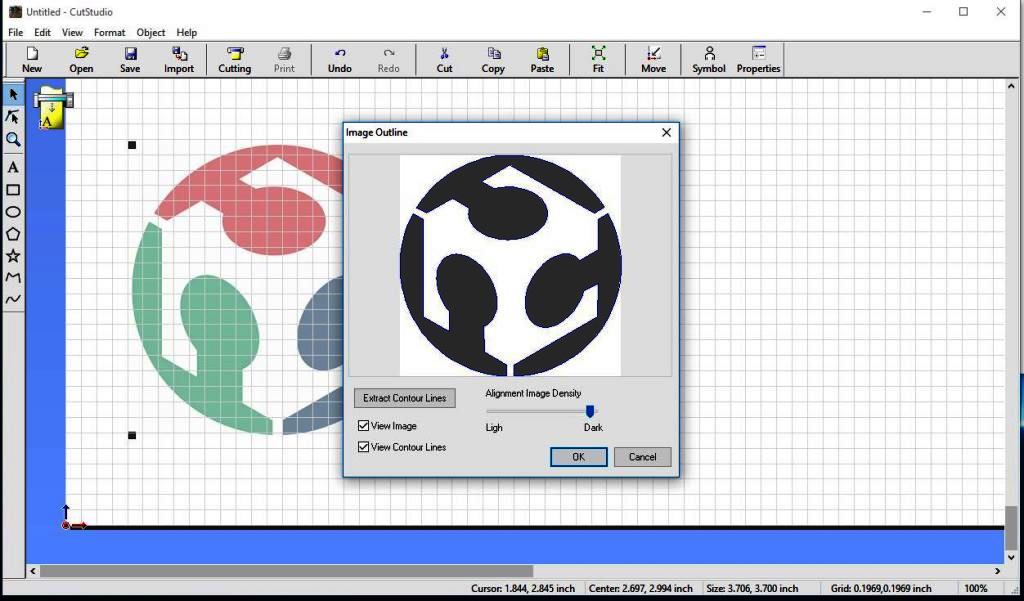
- I imported the FABLAB Logo JPG file to the roland cut studio, right click on the image and selected "Image Outline", then in the resulting window I chose Extract contour lines.
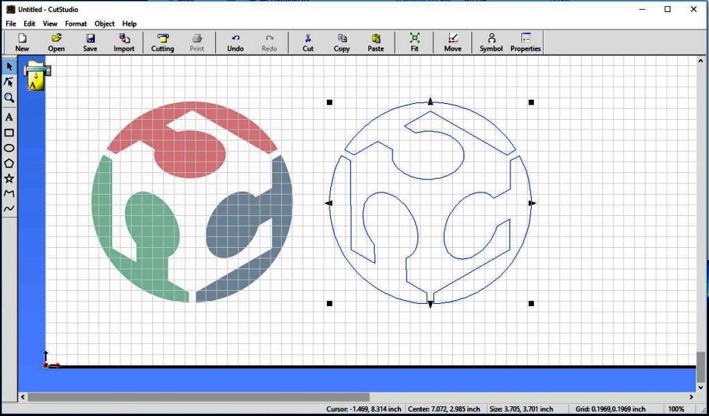
- click on the print icon, cutting setup then choose the Roland from the printers menu. click on properties and in the resulting window let the machine identify the size of the sheet by clicking "Get from the sheet".
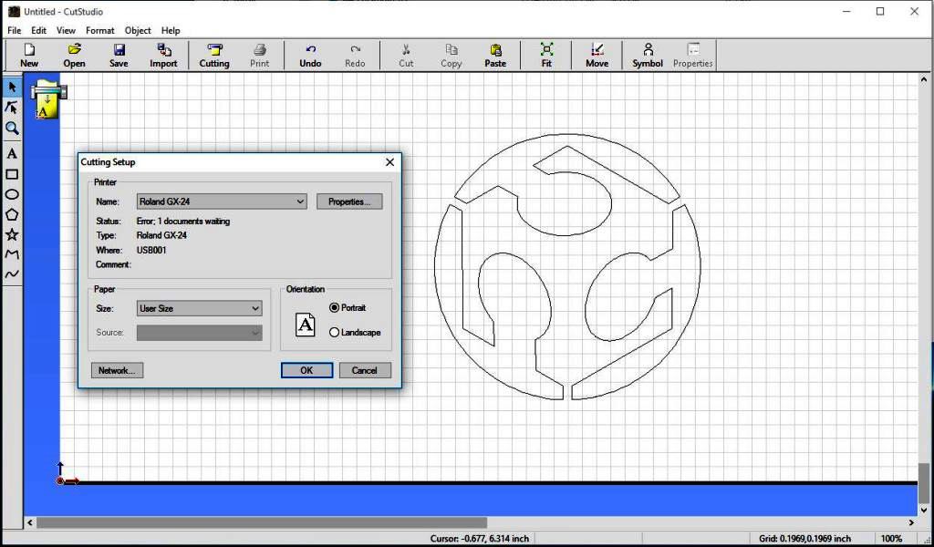
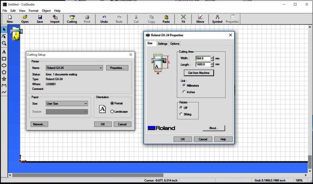
- Now we are ready to cut!.
- I did run print on the machine using the default settings and here are the results.
Files:
- Group Assignment Laser Cutter Fusion360 File
- Group Assignment Laser Cutter DXF File
- Notch Test (COMB) Fusion 360 File
- Notch Test (COMB) Fusion DXF File
- Living Hinge Book Cover DXF File
- Pressfit Enclosure Fusion 360 File
- Pressfit EnclosureFusion 360 File
- Pressfit Enclosure DXF File
- Fab Academy Logo Image File