WEEK 13 - INTERFACE AND APPLICATION PROGRAMMING
INTRODUCTION
This week we are requested to create an application and a GUI (Graphical User Interface) that works on android phones or tablets to interface with Input or output board we created. I created a board that perform communication via BLUETOOTH module HC-05 and I decided to build an interface to interact with it using MIT App Inventor.
Assignment Description
- Write an application that interfaces with an input and/or output device that you made, comparing as many tool options as possible
Learning Outcomes
- Interpret and implement design and programming protocols to create a Graphic User Interface (GUI).
Have you (Checklist)
- ✔ Described your process using words/images/screenshots.
- ✔ Explained the GUI that you made and how you did it.
- ✔ Outlined problems and how you fixed them.
- ✔ Included original code.
STEPS PERFORMED:
CREATING THE INTERFACE USING MIT APP INVENTOR
- I decided to use the MIT APP INVENTOR to build my Application because it is easy to use and interact with via a simple graphical interface. If you are new to MIT APP INVENTOR you can go through THIS TUTORIAL to know the basics.
WHAT IS MIT APP INVENTOR?
App Inventor for Android is an open-source web application originally provided by Google, and now maintained by the Massachusetts Institute of Technology (MIT). It allows new comers to computer programming to create software applications for the Android operating system (OS). It uses a graphical interface, very similar to Scratch, which allows users to drag-and-drop visual objects to create an application that can run on Android devices. In creating App Inventor, Google drew upon significant prior research in educational computing, as well as work done within Google on online development environments.
App Inventor for Android is an open-source web application originally provided by Google, and now maintained by the Massachusetts Institute of Technology (MIT). It allows new comers to computer programming to create software applications for the Android operating system (OS). It uses a graphical interface, very similar to Scratch, which allows users to drag-and-drop visual objects to create an application that can run on Android devices. In creating App Inventor, Google drew upon significant prior research in educational computing, as well as work done within Google on online development environments.
- Download the installer from THIS LINK .
- Locate the file AppInventor_Setup_Installer_v_1_2.exe (~92 MB) in your Downloads file or your Desktop, open the file and click through the steps of the installer.
- Open your browser and go to THIS LINK then logon.
HOW MIT APP INVENTOR WORKS?
- MIT APP INVENTOR Platform has 2 main views and you can switch between them:
- DESIGNER VIEW: where you can make the Interface and the design of the application.
- BLOCKS VIEW: where you can add the functions of the application.
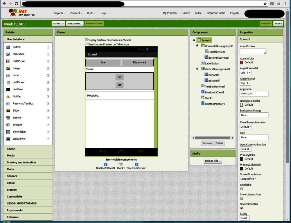
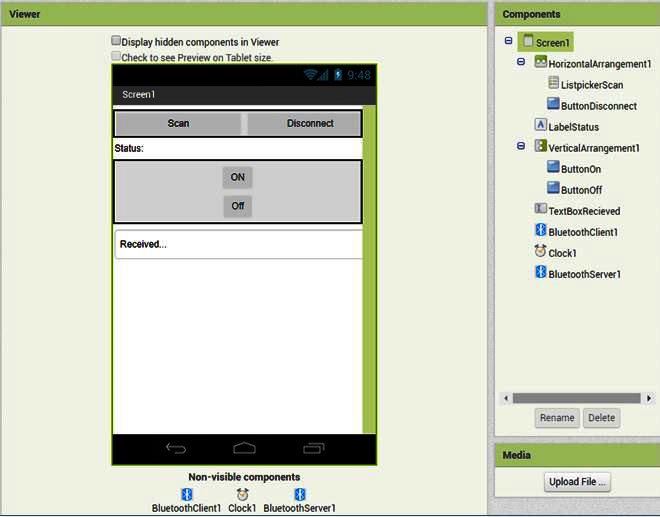
- IN DESIGN VIEW: you will find the components menu where you can reach add components to your interface and you can change their properties by clicking on them and changing them from properties menu.
- From the top menu: Go to "Projects" -> "Start New Project" .
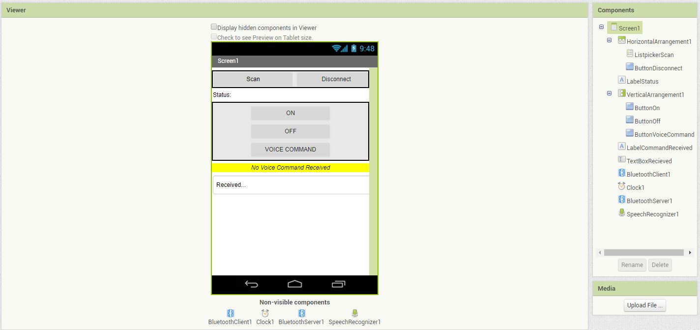
- In Designer View - we need to add some buttons to find and connect to our board over Bluetooth as follows: .
- Drag a HorizontalArrangement from the Layout drawer in the Palette and add "ListPicker" and "Button" to it.
- Rename the ListPicker: "ListPickerScan" and the button "ButtonDisconnect".
- Change their text to "Scan" and Disconnect".
- Below the Horizontal Arrangement add a Label and rename it "LabelStatus" and change its text to "Status: ".
- Drag a VerticalArrangement from the Layout drawer in the Palette and add 2 Buttons to it.
- Rename the 2 buttons "ButtonOn" and "ButtonOff".
- Change their text to "ON" and Off".
- Below the Vertical Arrangement add a TextBox and rename it "TextBoxReceived".
- From the Palette -> "Connectivity" -> Drag "Bluetooth Client", After it is are dragged onto the Viewer it will appear below the main screen, since it is a non-visible component and get the name "BluetoothClient1"
- From the Palette -> "Sensors" -> Drag "Clock", After it is are dragged onto the Viewer it will appear below the main screen, since it is a non-visible component and get the name "Clock1"
- In Block View - We want to set up the application to scan for available Bluetooth devices to show them in the ListPicker , connect to the bluetooth device we select and finally to send "1" when we click on "ButtonOn" and "0" when we click on "ButtonOff" . To do this, we will do the following:
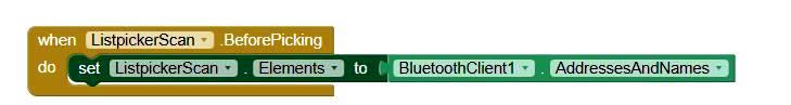
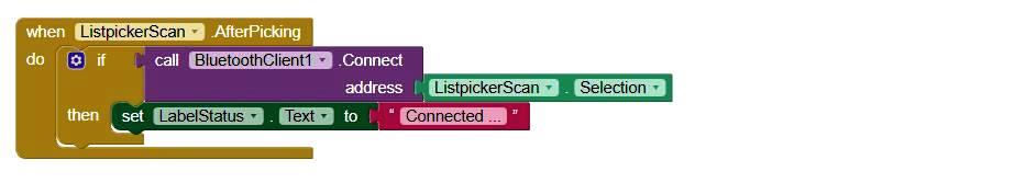
- To Pre-populate the ListPicker by the bluetooth devices, From the Blockes pane build the blocks below.
- Then add the blocks below to: connect to the Bluetooth device selected then change the status label to "Connected".
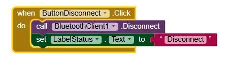
- I also added the following blocks to disconnect the bluetooth device and change the status label to disconnected.
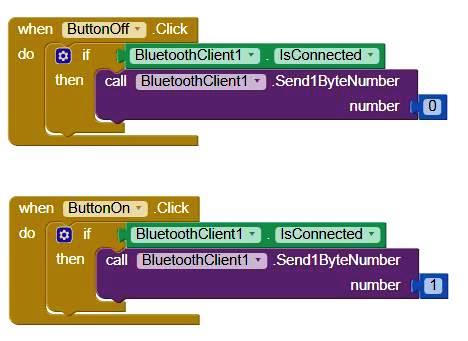
- To enable the "ButtonON" and "ButtonOff" buttons to send "1" amd "0" respectively add the blocks below.
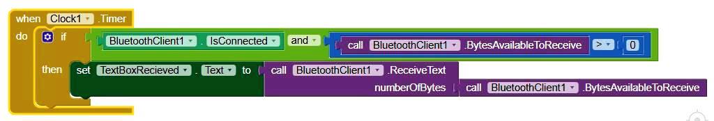
- Finally, to receive the incoming feedback from the Bluetooth device (i.e: The text sent from the HC-05 TX), I added the blocks below.
- Now time came to upload your program to an android device to do so you need to follow the following steps or you can go to THIS LINK for more details:
- Download and install the MIT AI2 Companion App on your phone.
- Connect both your computer and your device to the SAME WiFi Network.
- Open an App Inventor project and connect it to your device.
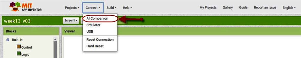
- In the project you created -> Go to top menu -> Choose "Connect" and "AI Companion"
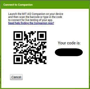
- A dialog with a QR code will appear on your PC screen. On your device, launch the MIT App Companion app just as you would do any app. Then click the “Scan QR code” button on the Companion, and scan the code in the App Inventor window
- Within a few seconds, you should see the app you are building on your device. It will update as you make changes to your design and blocks, a feature called “live testing”.
TESTING THE APPLICATION WITH HC-05 MODULE - USING ARDUINO
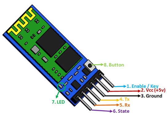
- To test the program I needed to have a Bluetooth module connected to my board that can act as a receiver / sender to the Bluetooth connection that I initiate from the Android device. I choose the HC-05 Bluetooth module, few facts about the HC-05 are listed below but to know more details you can check the HC-05 DATASHEET or check THIS LINK.
QUICK FACTS ABOUT HC-05 MODULE:
HC-05 Bluetooth Module is an easy to use Bluetooth SPP (Serial Port Protocol) module, designed for transparent wireless serial connection setup. Its communication is via serial communication which makes an easy way to interface with controller or PC. HC-05 Bluetooth module provides switching mode between master and slave mode which means it able to use either for receiving or transmitting data.
SPECIFICATIONS:
- Input Voltage: DC (3.3 - 5) Volts
- Communication Method: Serial Communication
- Operation Mode: Master and slave mode can be switched
- I decided first to test the HC-05 Bluetooth module using Arduino to ensure both the module is working normally and to ensure that the MIT APP INVENTOR Program I created has no flaws.
TRIAL 1 - FAILED
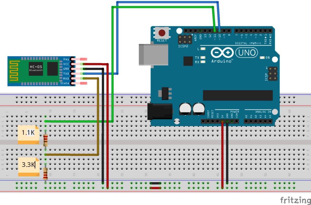
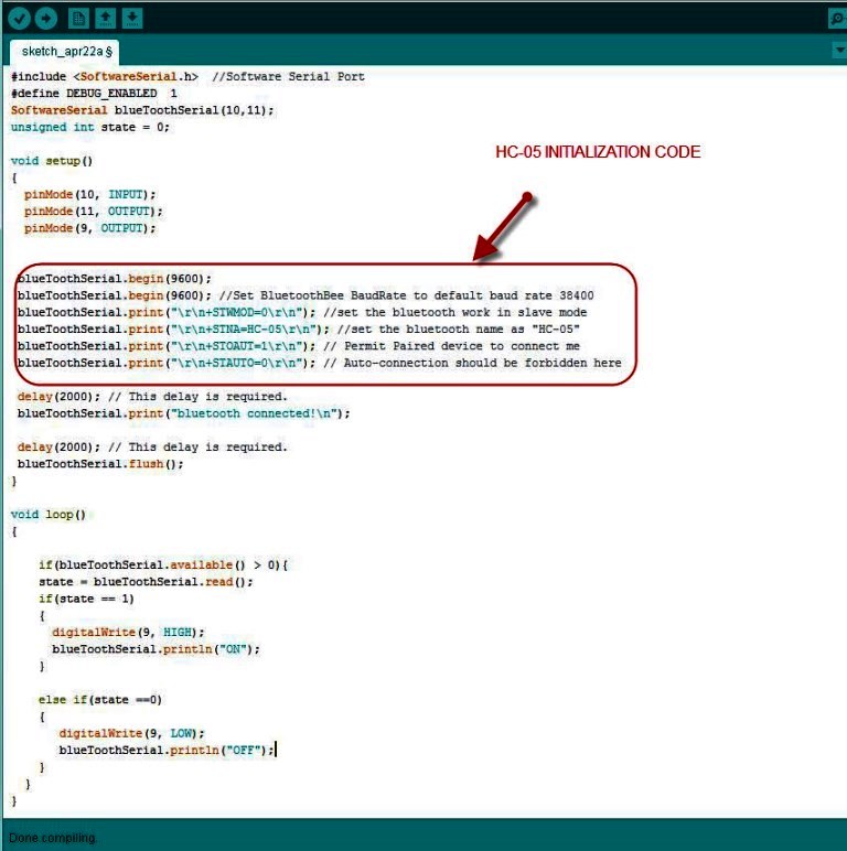
- I connected the HC-05 module to the ARDUINO UNO board as shown below.
- I compiled the code with no errors, uploaded it and it worked fine on ARDUINO UNO.
- When I modified the PINs to suit the ATTINY45 and did compile the code (With no errors) then uploaded it. I found that HC-05 keep rebooting and never get connected successfully.
- The below warning message appeared that hte program might be unstable as the "Global Variables" are consuming 89% of the availble space!!
- I tried several ways to reduce the size (Which did not work) like:
- Ensure that variables types are effeciently chosen
- Minimize any un-needed Global Variables.
- Reduce the messages in the Serial.Println commands.

ISSUES FACED AND HOW IT WAS RESOLVED?!:
- CAUSE(S):The error faced was due to the fact that the global variables consumed a lot of the allocated memory leaving the whole sketch un-stable during the execution. One global Variable is the SoftwareSerial Object that by itself reserve a lot of space. lso the HC-05 Initialization configuration commands in the SETUP() function.
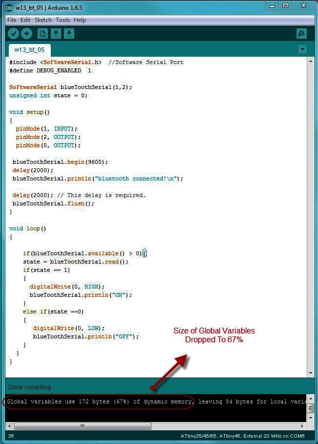
- RESOLUTION: I changed the HC-05 default configuration using the AT commands and accordingly that elminated the need to write the code to initialize the HC-05 in the SETUP() function. this freed-up a lot of memory and reduced the used global variables spce to 67% of the allocated memory.
TRIAL 2 - SUCCEEDED!
- I connected the HC-05 module to the ARDUINO UNO board as in TRIAl 1.
- I performed the following steps to Enter the "AT MODE":
- Disconnect the +5v line from the modules end.
- Press and hold the small button on the bottom right of the HC-05 board (DO NOT RELEASE IT!)
- Reconnect the +5v connection
- Now Release the switch. Notice that the led on the module starts blinking once every two seconds, slower than normal disconnected mode.
- Upload the code below to the Arduino.
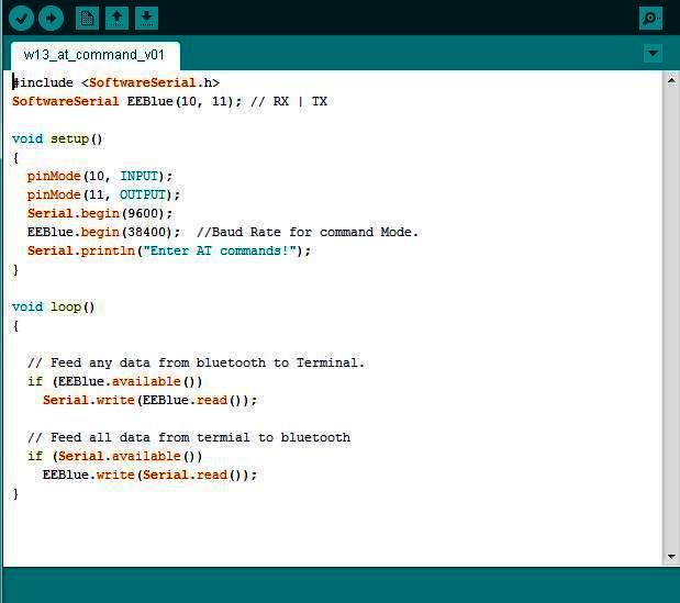
- Open up the terminal hit AT and check if the module echos back OK!.
- I executed the following AT commands to change the HC-05 default configuration:
- AT+RMAAD : Clears any previously paired devices
- AT+ROLE=0 : Sets the device to slave mode.
- AT+RESET : Resets the module, required after changing the previous settings.
- After this reset, your module may revert from AT command mode, so you will need to go through the process to set it in command mode again.
- AT+CMODE=1 : Sets the CMODE to allow connection to any device.
- AT+PSWD=1234 : Sets the password to 1234 which should be set the same on the slave device
- AT+INIT: Start Serial Port Profile, it may return error(17) which just means it’s already loaded
- Now we are ready to upload the code and this time without hte HC-05 initialization code in the SETUP() Function.
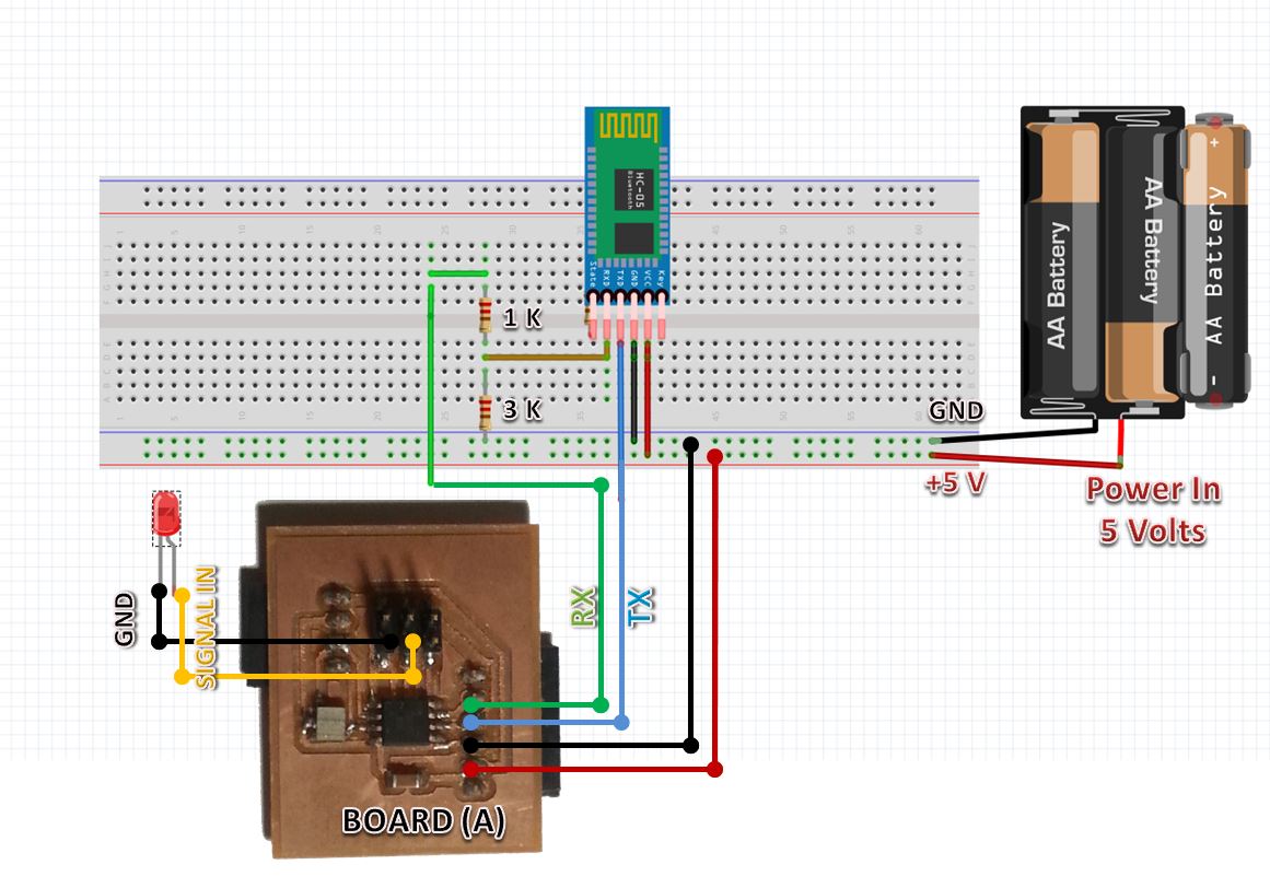
- To test the functionality, I uploaded the following code to the ATTINY 45 and connectected a LED with wire to test the received "1" or "0' sent from the android programs.
- The result is SUCCESS!
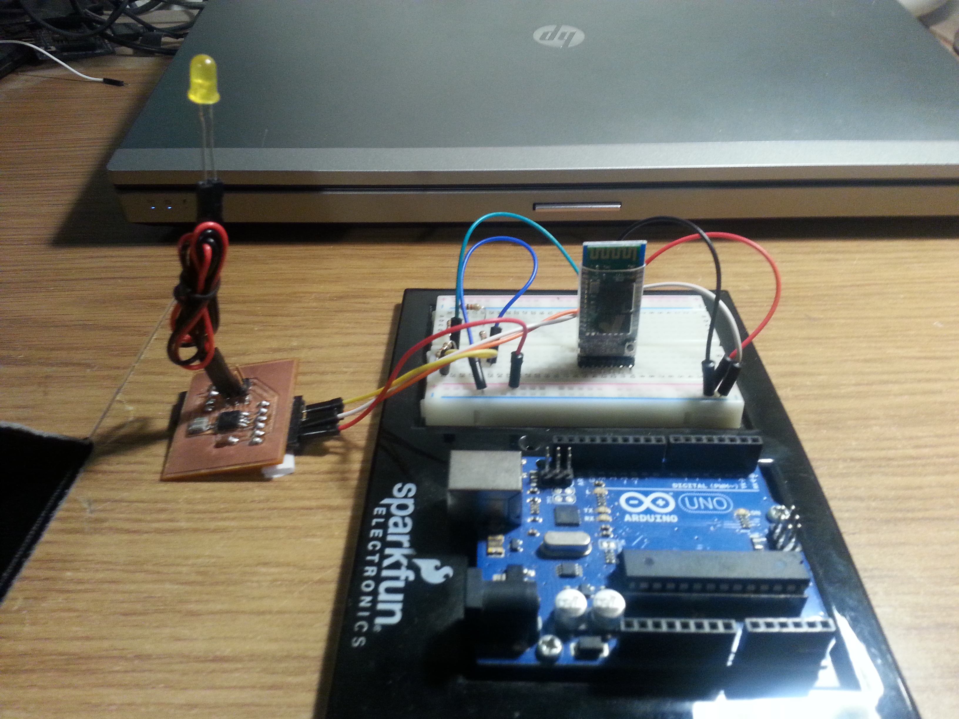
- The connection diagram is as below.
TESTING THE APPLICATION WITH HC-05 MODULE - AND CONNECTING IT TO OTHER BOARD
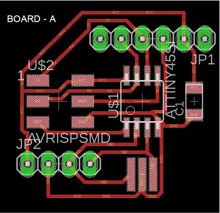
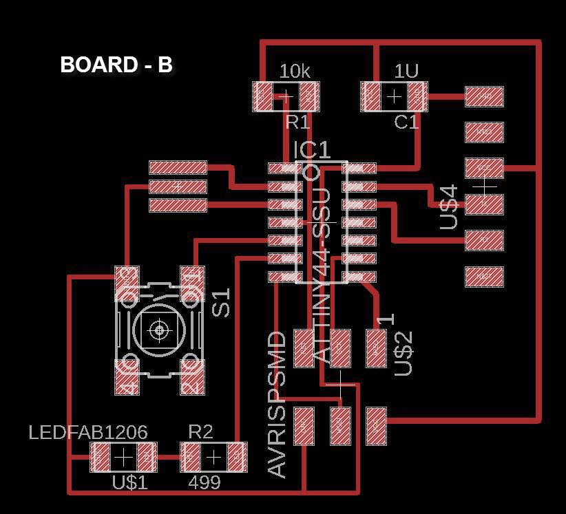
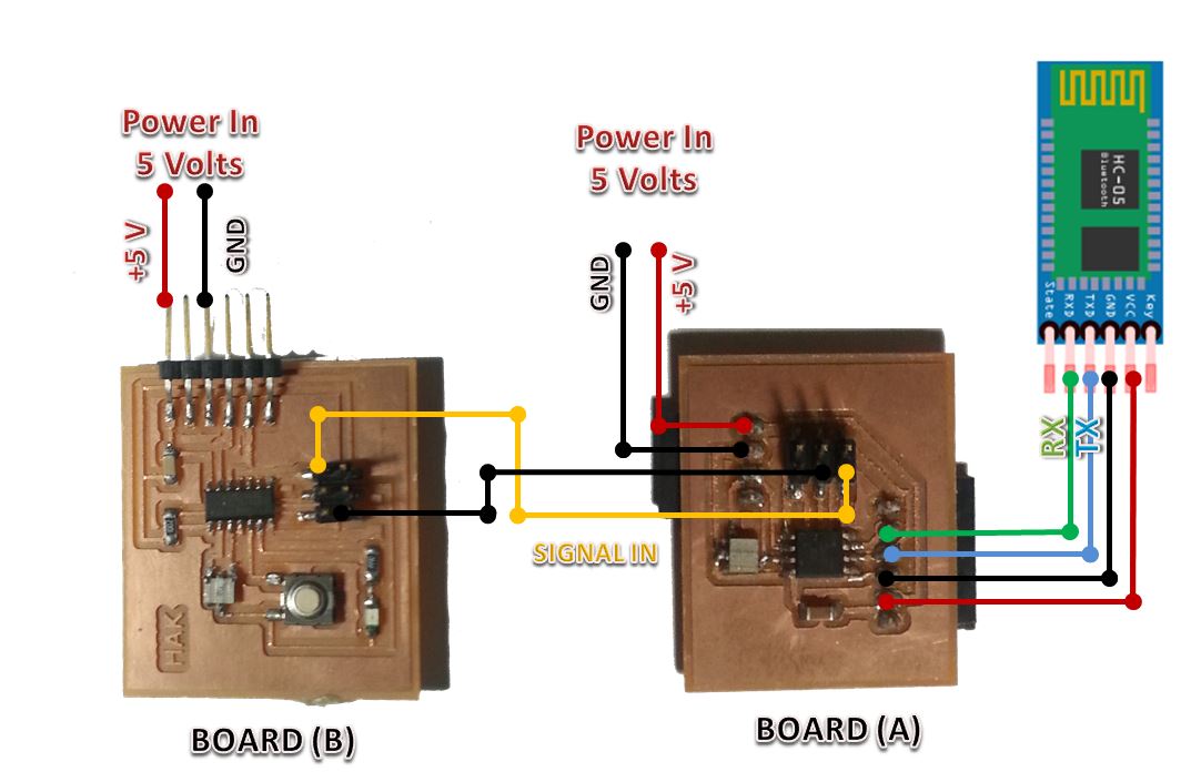
- This time I decided to connect the HC-05 to the ATTINY45 board I created (refered to in the following steps as BOARD A) and have jumper cables connected from it to the board we created in WEEK 7 we will refer to it as Board B
- The plan is simply to achieve the following: Anroid phone send ON command to HC-05 / Board A -> Board A set a PIN to High -> The High Signal is transfered to Board B -> once it is sensed as High a LED lights up.
- I connected the 2 boards as shown in the below photo.
- I created the following sketch to be uploaded to Board B, then I compiled it and uploaded it.
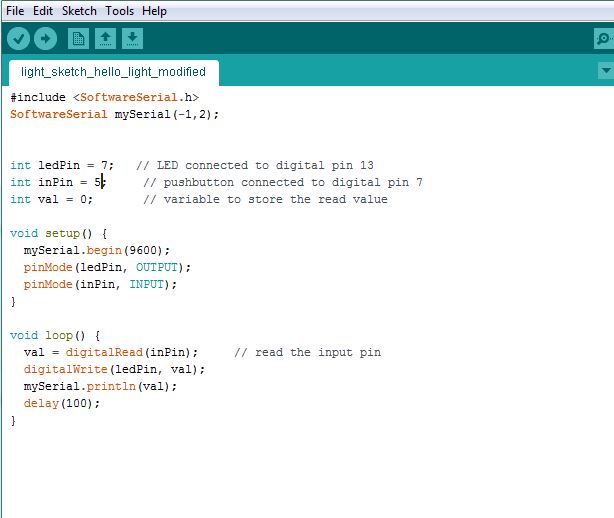
- I powered the boards up and ran the application and the results are as shown in the below video.
WALKING AN EXTRA MILE!!! - LET'S MAKE THE BOARD LISTEN AND OBEY
- Well.. If we reached that far then why not to walk an extra mile. I decided to add a feature to the android program and make it accept voice commands.
- IN DESIGNER VIEW: I added a button to initiate the voice recognition once pressed, a label to display the voice command taken and a voice recognition component (located under the media tab) as shown below.
- IN BLOCKS VIEW: I added the blocks shown below.
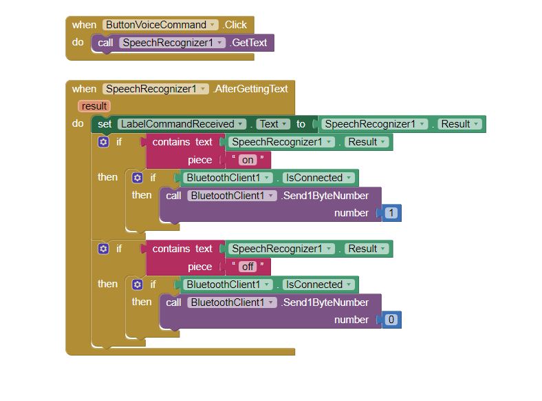
- IN BLOCKS VIEW: I tested the code and the result is as shown in the video below.
HOW TO PUT THIS APPLICATION AND BOARD IN USE IN REAL LIFE? (APPLICATION AND IMPLICATIONS)
- I have always been fascinated with home automation, so I decided to make this application and board control my office light .
- The first step was to apply a relay to be able to control 220 AC Volts using a 5 Volts DC signal coming from my HC-05 Board A.
- I watched the video in THIS LINK to know how to connect a solid state relay and it was so useful.
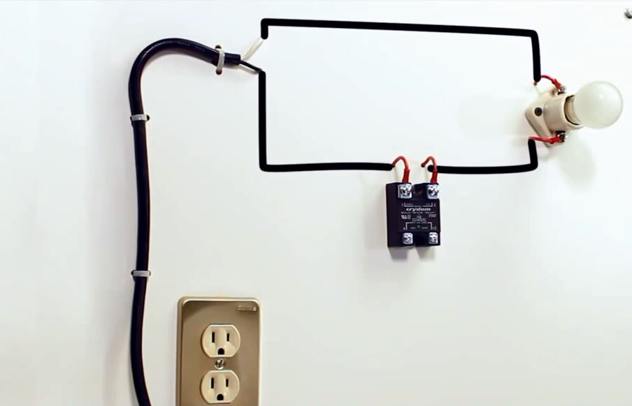
- I connected in the other 2 pins (pin3 - the +ve DC Signal) and (pin4 - the -ve DC Signal).
- I tested and the result was Success as per the video below. Now I have my simple light home automation system...
Files: