| This week | |
|---|---|
| Presentation wildcard | http://academy.cba.mit.edu/classes/wildcard/index.html |
| video of the review (machine design) | |
| video of the lecture | |
| video of the recitation FABx |
| Assignment | Used software | Files/Downloads/links |
|---|---|---|
| Group Assignment | produce test coupons for your composite fabrication process(es) | |
| fisbee outside mall | FreeCad | frisbee_outside.fcstd |
| fisbee inside mall | FreeCad | frisbee_inside.fcstd |
Wildcard week, but we are doing composites and I am doing parts of the assignment for the molding and casting week :)
This week is one of the latest weeks before everything fabacademy needs to be finished. So this week I’m gonna do a 2 in 1. For the molding and casting assignment i created a beautiful and original tempeh tray growing mold, BUT created it with Partwork and not Partworks3D. And the assessment says:
- Explained how you designed your 3D mould and created your rough and finish toolpaths for machining
I designed a 3d mould, but created it with Partworks in 2D, machining it in 2D with different sized pockets.
So that part of the assignment i am re-doing this week where i am going to create a 3D mould to be milled out in a block of foam, using the rough and finish toolpaths of Partworks3D.
The design
As you may have noticed, making 3d designs is a thing i really have to learn. So this time i tried to keep it simple, to have some space in between to finalize my documentation. I combined 2 things:
- during the local lecture Emma showed us a well done frisbee
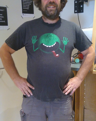
- i can’t see goodbye to my old shirt’s
So i will make a fishbee out of my old shirt’s.
I made 2 mould, a in- and outside one, with 2 mm space in between. It is made with FreeCAD, and after several project where i used FreeCAD before, this one was the less frustrating experience.
- Creating a circle in sketch mode
- give it the right diameter
- change to part mode
- extrude
- create a fillet on the upper edge
- change to part design mode
- create a block
- give it the right dimensions and position
- select the filet and the cube and “make a cut out of 2 shapes”
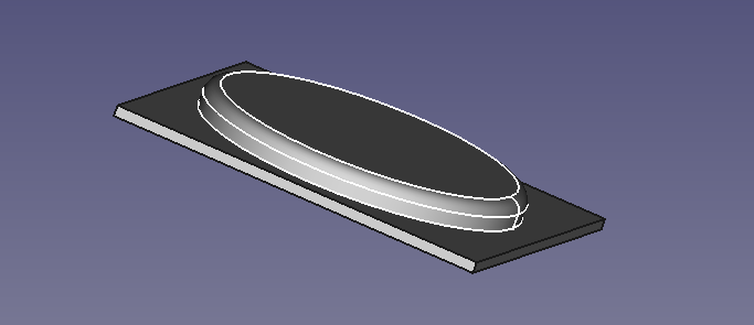
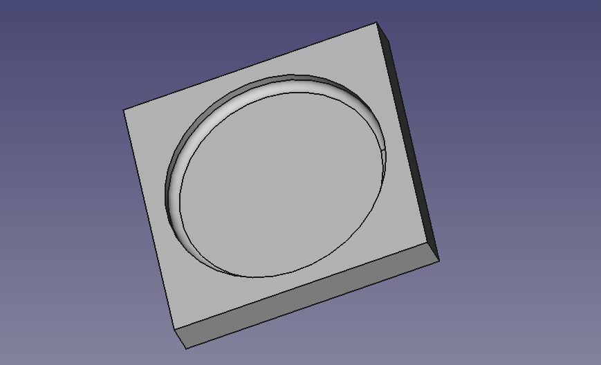
This is the result.
Because the image on my shirt was bigger than the frisbee i decided to make a bigger frisbee, which was easy, because the whole design was parametric. Dimensions of the design are:
weight: 35cm
length: 35cm
height: 25mm

circle (frisbee):
inside: 298mm
outside: 300mm

thickness of the firsbee: 2mm
The outside mall:
I saved both designs as stl for importing in Partworks3D.
Setting up Partworks3D: rough and finish toolpaths
Part of the molding and casting assignment
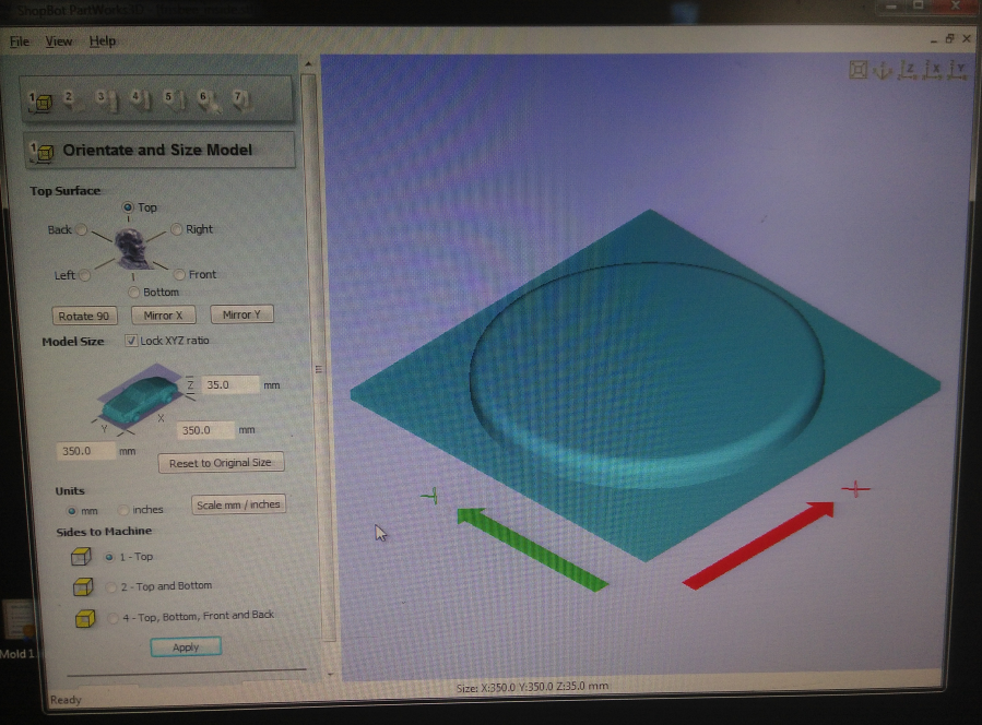
Partworks3D looks like Partworks but has a more organized approach. When you start Partworks3D you are asked to import you 3d design. The first screen named “Orientate and Size Model” handles the position, placement and measurements of the 3D design.
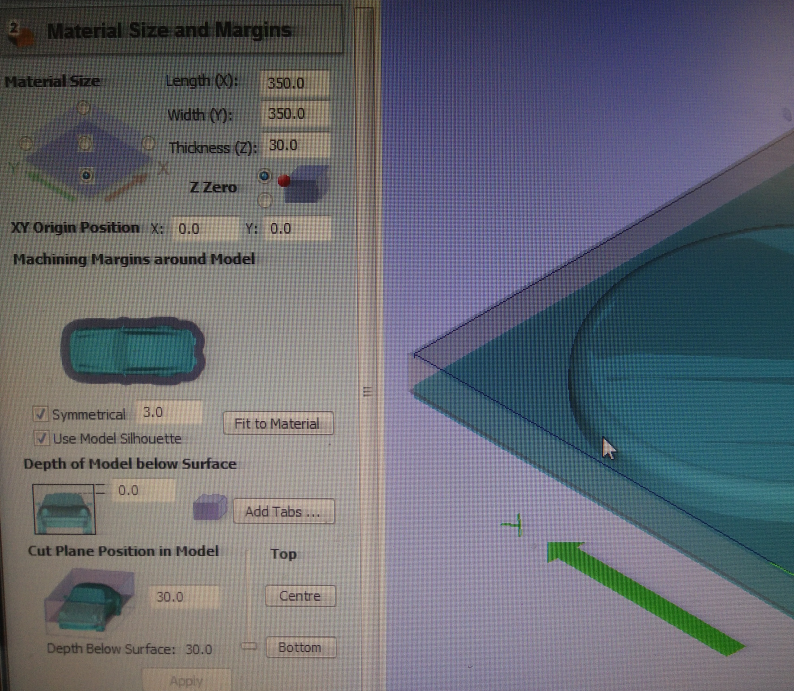
After placing the design you press next, and come in the second screen named “Marterial Size and Margins”. Here you set the material size and origin, margins around the model, dept of the model below surface, cut plane position in the model. My design had the frisbee with height 25mm and 10mm groundplate. After measuring the margins of the milling bit, see the documentation of the computer controlled machining week, i decided to thickness to 30 instead of 35. The endmills depth coming out of the collet was hardly 36mm, and i wanted a bit more space between the material and collet. And because the material was thicker than i could machine, i had to do the cut out of the model with a handsaw anyway. So thats why i decided go for 30mm thickness without a worry :)
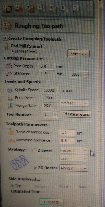
For the roughing toolpath the following values were set:
- End Mill: 5mm

 - Cutting Parameters:
 - Pass dept: 5mm
 - Setover: 1.5mm (30%)

-Feeds and Speeds:
 - Spindle Speed: 18000rpm
 - Feed Rate: 120mm/s
 - Plunge Rate: 25.0mm/s

- Toolpath Parameters:
 - Rapid clearance gap: 1.0mm
 - Machining allowance: 0.5mm

- Strategy
 - 3D Raster / Along Y

For the roughing finishing Toolpath the following values were set:
- End Mill: 5mm

 - Cutting Parameters:
 - Pass dept: 5mm
 - Setover: 0.6mm (12%)

-Feeds and Speeds:
 - Spindle Speed: 18000rpm
 - Feed Rate: 100mm/s
 - Plunge Rate: 25.0mm/s

- Toolpath Parameters:
 - Rapid clearance gap: 1.0mm
 - Raster Angle:  Along Y
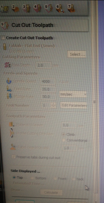
The foam is to thick (10cm) to machine it all the way through, so i skipped the cut out toolpath and will do it with a handsaw.
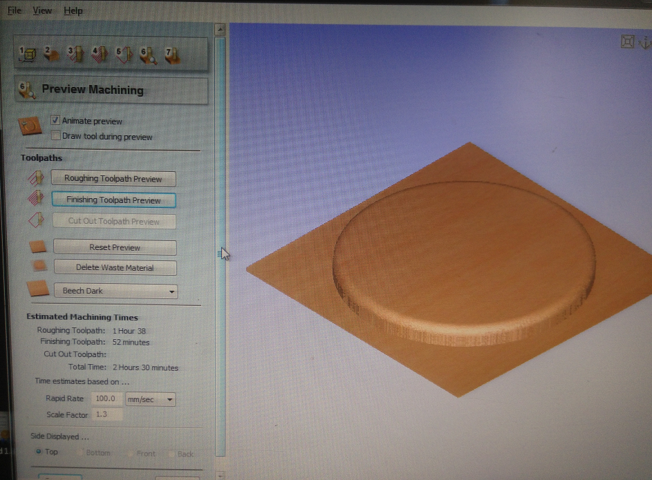
In the Peview Machining screen i watched the simulation of the roughing and finishing toolpath. It looked as a perfect job.

I saved the roughing and finishig toolpaths in separate files. These files i imported in the shopbot software for milling.
Machining
With double sided tape i attached the foam to the sacrificial layer. To give the foam a more solid place, i put 4 wooden pieces on each side of the foam.
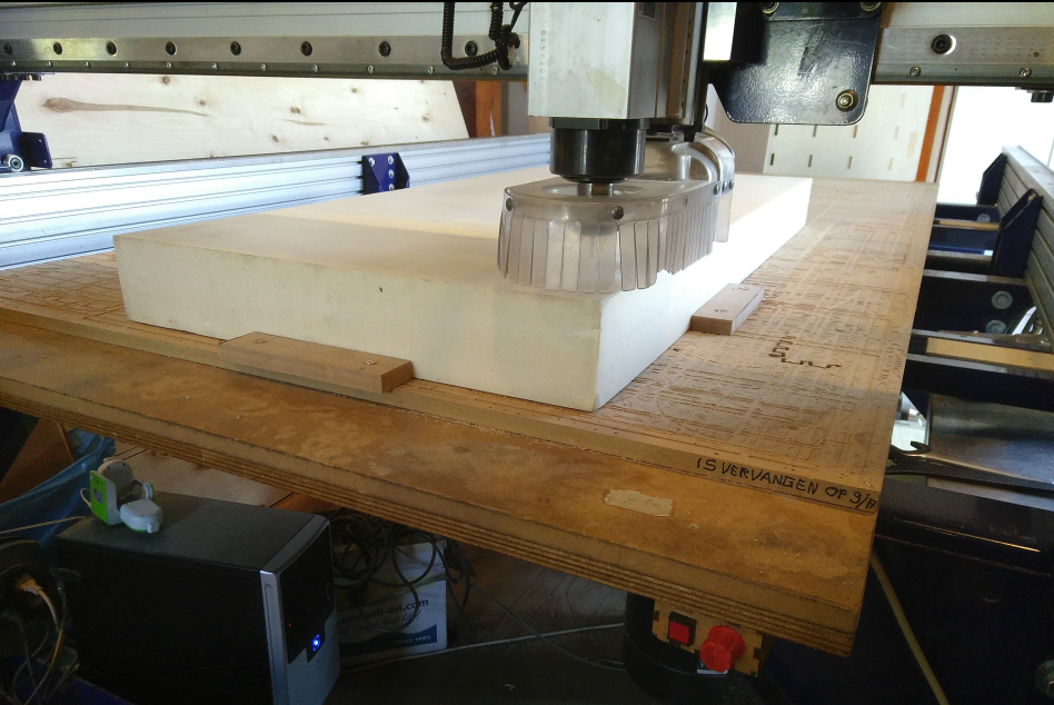
I used my documentation of the computer controlled machining week to setup the Shopbot and that went pretty well. Although documentation will never be my favorite part of the job, i finally see the advantages and the necessarily of documenting in a good and organized manner.
Bee swarm
While in the middle of the finishing toolpath (2hrs job) i got a phone call from home. Outside it beautiful weather so one of my queen bees took the decision to move to a new home. Yesterday i did a routine control of the hives, in this time of year i do that ones a week. And yesterday i saw and removed all queen cups, which were already halfway. Probably i didn’t noticed all cups, so that’s the reason i had to leave the job (actually i finished the running one) continuing with the 2nd half tomorrow.
Halfway home another phone call from home: My girlfriend already captured the swarm in a kieps (or skep). Following the old tradition she now is the new “owner” of the colony.
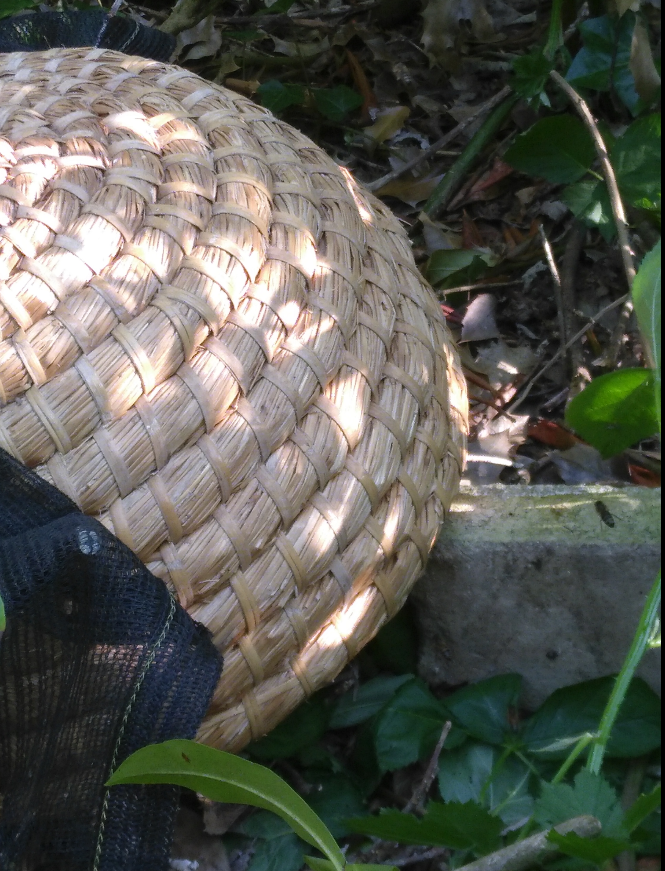
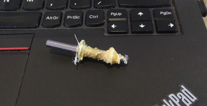
And look what is inside the skep!
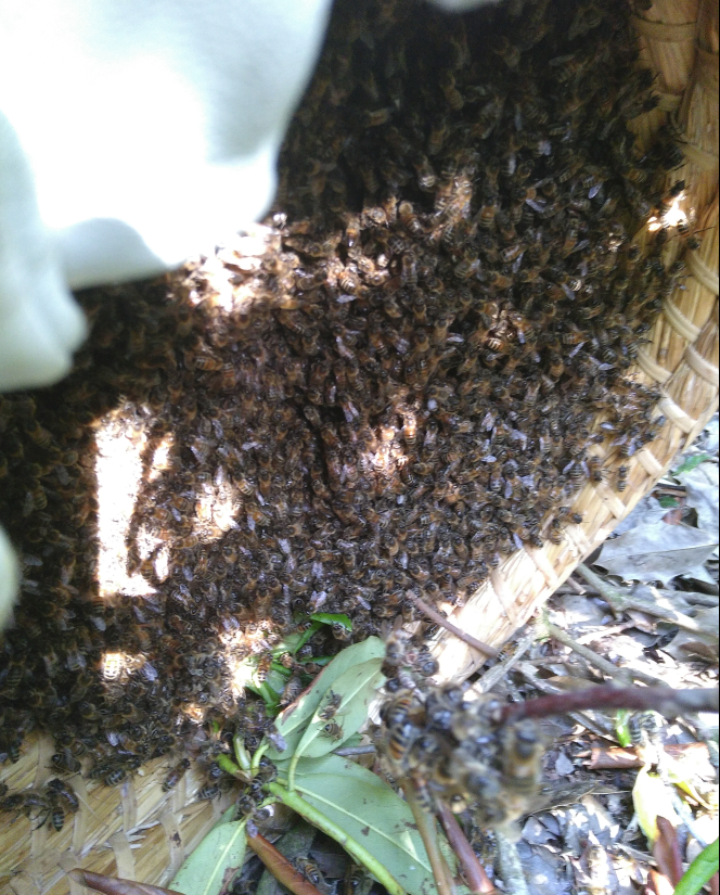
and continou the next day
With the bees everything is fine. They are still in the skip, bottom covered by a netting so they are locked in, but get fresh air. The skip is put in the garage, the coldest place in the house at the moment. After 2 days they will get their new home and put outside again.
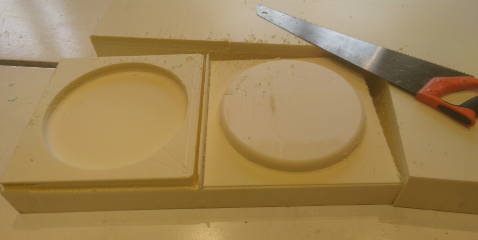
This morning i milled the inside mould without problems, using the same settings as yesterday. With a handsaw i separated the 2 parts.
For the top part of the mould i configured the finishing toolpath to do an extra pass at 90 degrees to the first pass (along Y). But halfway i decided that it wasn’t necessary and stopped the job on the shopbot, to save some time.
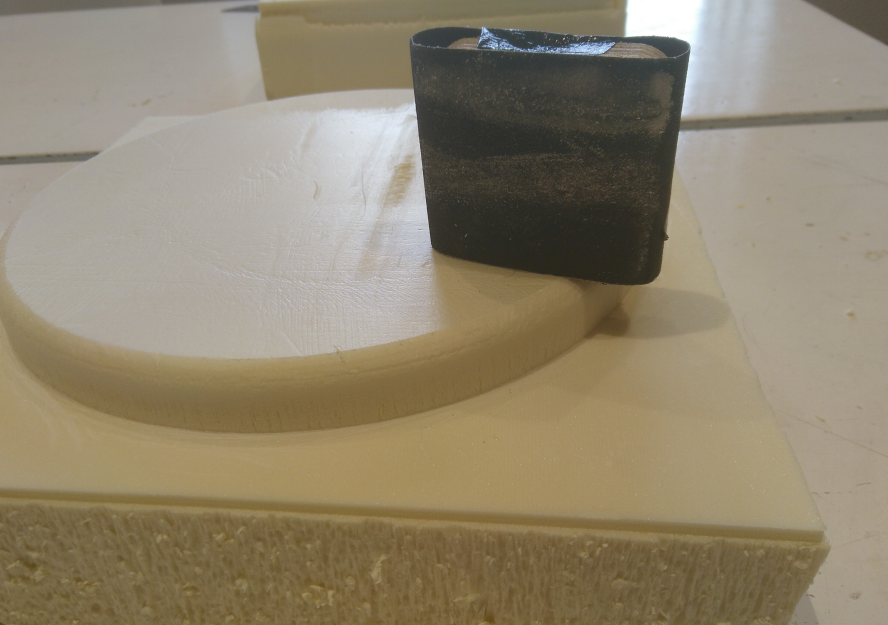
I did a little bit of sanding to get rid of some rough and loose parts.
Preparing the textiles
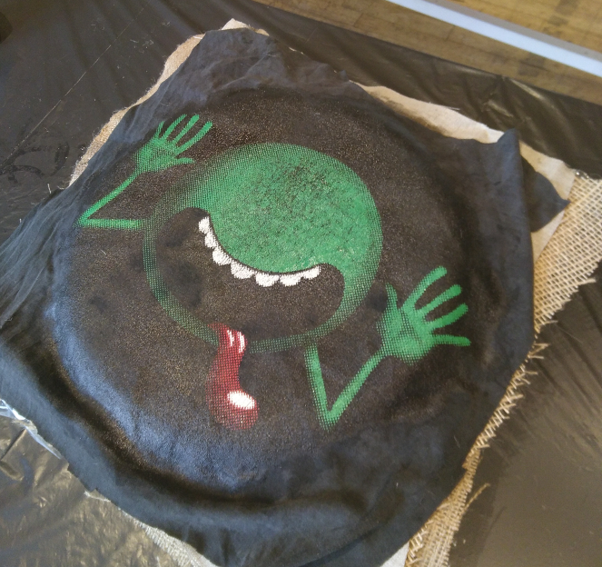
A last photo with my favorite shirt..
With a scissor i cutted the shirt in a way that i had a little overhang over the mould.
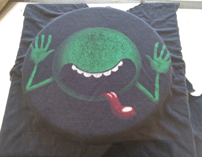
The same i did with 3 pcs of jutte. As you can see on the photo they are all different. Also the angle of the threads i differed to get a more solid state after curing with epoxy. The shirt is the top layer, underneath a fine mesh of jutte, followed by the a rough on and for the inside a rough but almost closed wired jutte.
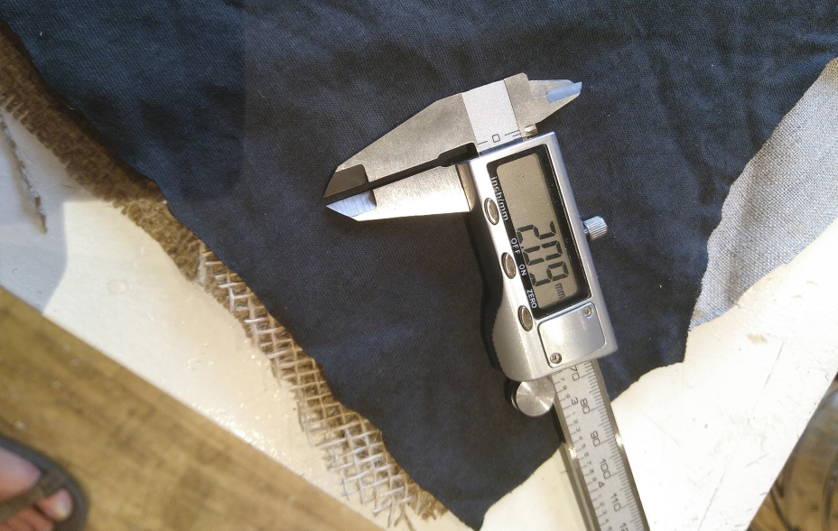
The thickness of all 4 layers is 2.09mm, enough to fill the space i gave it in between the 2 moulds.
Composite process
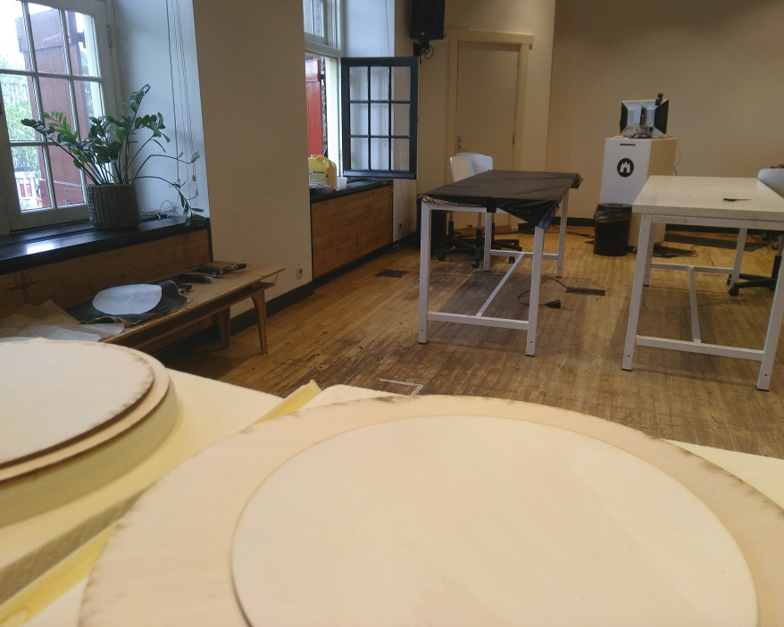
I prepared the space, by getting rid of all the mess around me. The window was opened for getting enough ventilation. In front of the window a table was covered with a plastic bag layer to protect the table from dripping epoxy and other hazardous and stickie stuff. The textile layer were put in the right order. The moulds and wood for the bottom and top part, used for protection of the foam when use glue clamps to pressure the textile in between of the 2 moulds, also were arranged on another table.
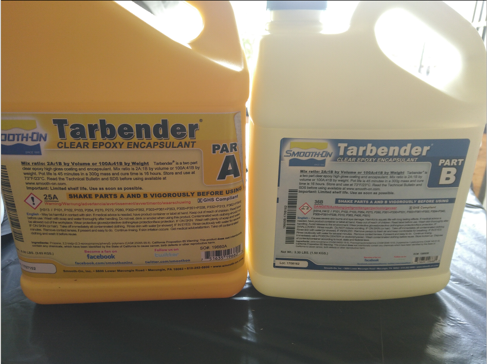
For the composite we use Smooth-on tarbender, clear epoxy encapsulant. It exists of 2 parts (A and B). Before mixing the 2 parts they both have to be shaked vigorously. You need 100gr of part A to be mixed with 41gr of part B. A precise scale was used for that. For the fisbee i mixed 160 gr part A and 66gr of part B to to get 226gr of epoxy. During mixing there is a chemical reaction that heats up the epoxy. The curing time is about 45 minutes. So after mixing 5 minutes i left the epoxy to cool down a bit.
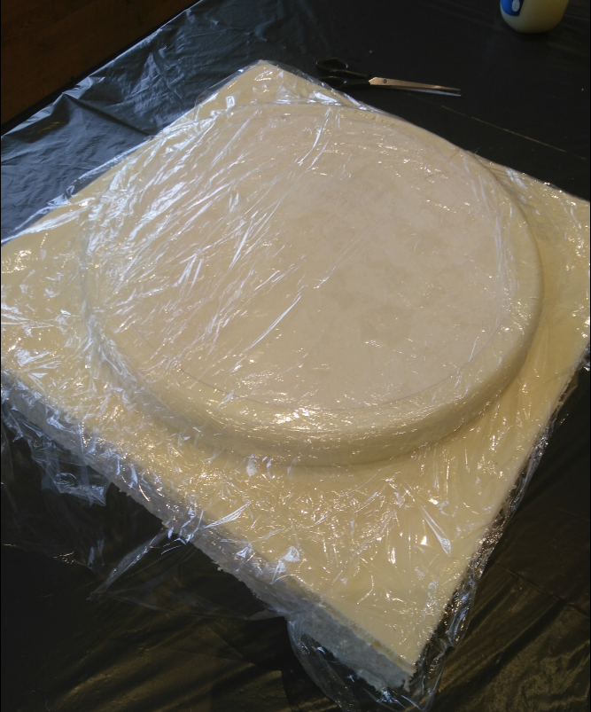
I covered the inside of the mold first with a round layer of baking paper to cover the abrasions it got from the loose dust collector during milling. Then a layer cling foil smeared with Vaseline is put on top. The vaseline protects the foil from curing with the textiles and epoxy.
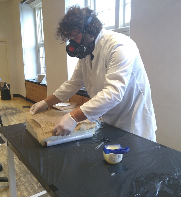
Now it’s time for the epoxy part. I covered my hands with gloves, my body with a lab-coat, my eyes with glasses and a gas mask for mouth and nose. I used a brush to put and spread the epoxy onto the textiles. I then used my fingers to massage the epoxy in all parts of the textiles.
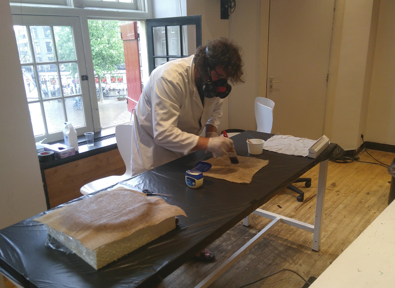
I turned around the textiles to also soak it from the other side. After that you put it in position on the mould.
After all 4 textile layers were done, a round layer of baking paper was put on top of the shirt (which was the last textile part). I did this because i think it flattens better than the layer of cling foil, that is really difficult to put on top without overlap and wrinkles.The rounded backing paper was smeared with a thick layer of vaseline to protect it from sticking onto the epoxy drained textiles.
The latest layer was again cling foil smeared with vaseline.
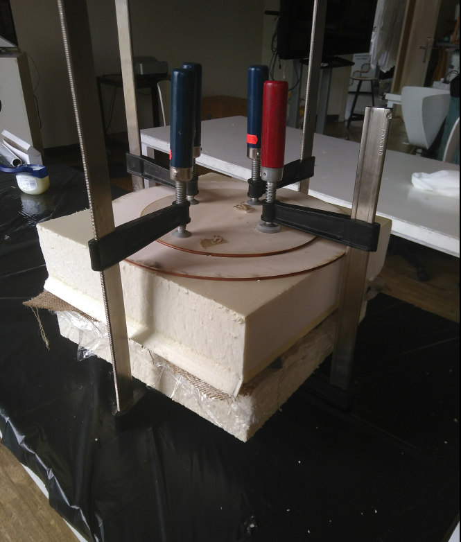
When finished with textiles, cling foil and lots of vaseline it was time to bring the outside mould in position. I had to pressure it real hard. It was also a bit of a scary part of the job, because you cannot see what happens inside with the textiles. Will there be overlap and wrinkles? I don’t know…
Layers of wood on top and bottom, protecting the foam from the glue clamps. The clamps were tightened really hard.
And now it was time to wait for 16 hours…
Frisbee
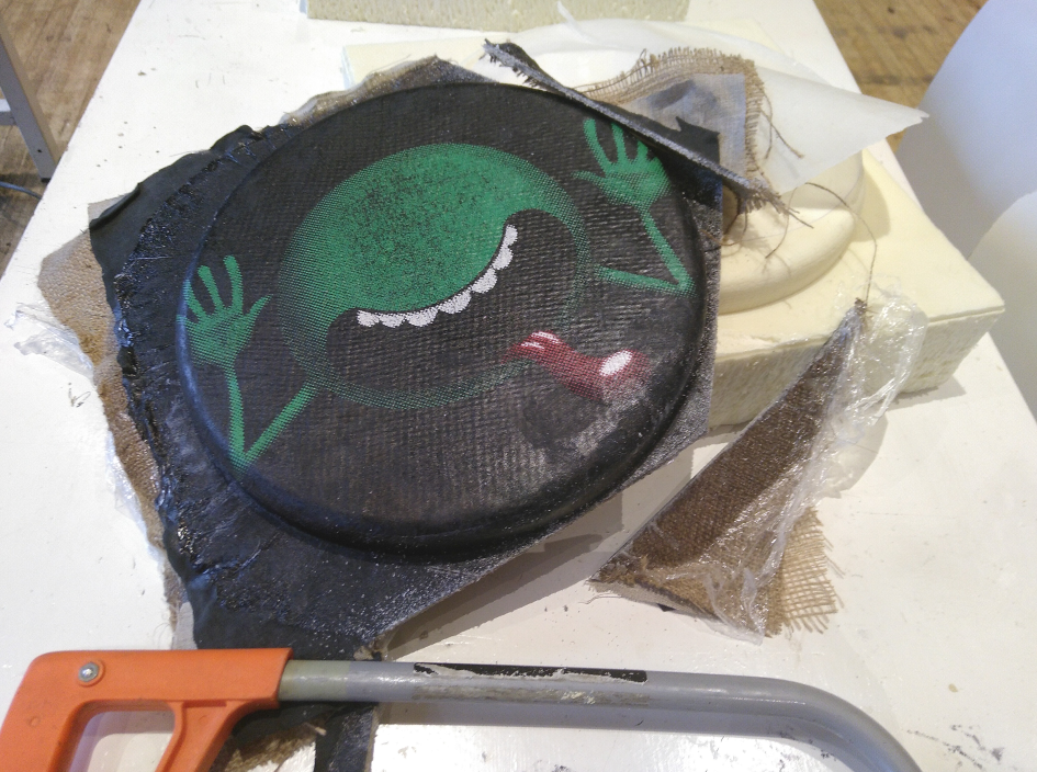
The next morning it was time to open the mould. The frisbee came out really well, but covered with a lot of vaseline. I used a handsaw to remove the parts on the side of the frisbee.
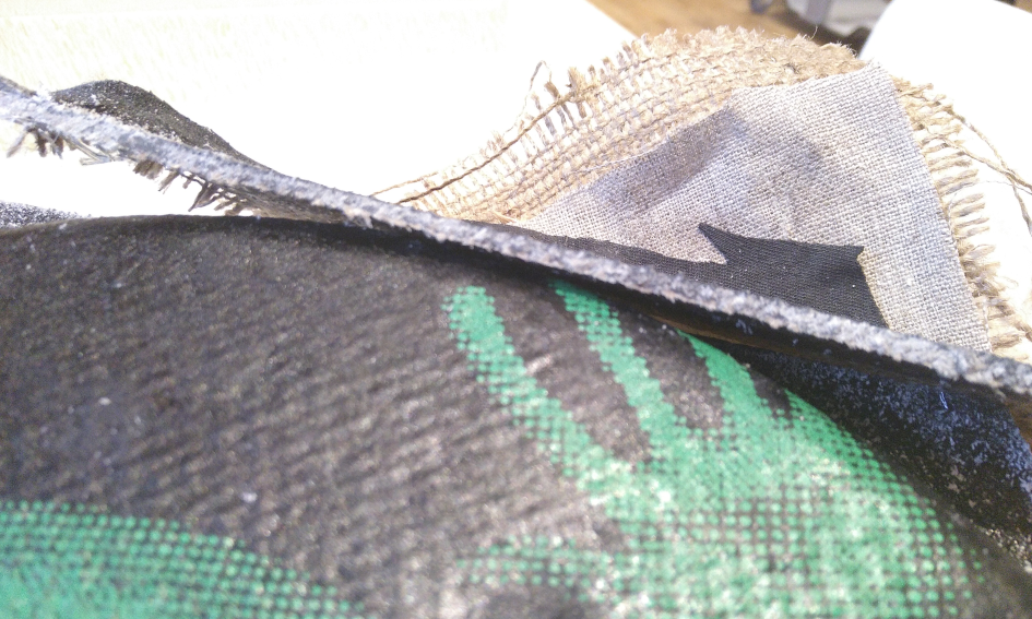
As you can see the 4 textile layers were completely solid, it really looked great.
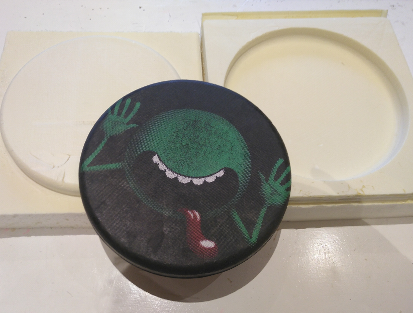
After a lot of sawing and sanding this is the final result. I am happy with it and probably my kids also!
Lessons learned
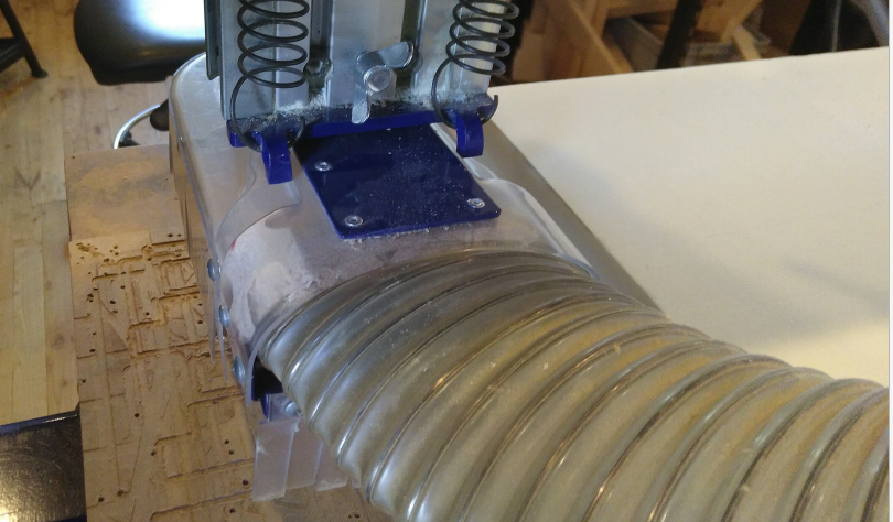
be sure to fasten the wingnut at the back of the assembly to keep the vacuum skirt up. During the roughing cut, the vacuum skirt became loose and damaged the foam at the place were i wanted to mill the inside mould. Luckily immediately noticed it and could stop the machine and tightened the vacuum skirt. I didn’t want to wast material for so little damage, so i continoud milling as planned and added a piece of backing paper to cover the small scarfs.
At the end of the rough cut the shopbot did a last round around the design, looked like it was the path of the final cut. The origin was close to the border (only 1 or 2 mm), so the thin layer of foam started to rap around the spindle and melt. I stopped the machine and since it was almost completely done, also stopped the complete job. Carefully but with some pressure, i removed the melded plastics.