| This week | |
|---|---|
| Presentation networking and communications | http://academy.cba.mit.edu/classes/networking_communications/index.html |
| video of the review (interface and application programming) | http://fab.academany.org/2018/lectures/fab-20180425.html |
| [video of the lecture | http://fab.academany.org/2018/lectures/fab-20180425.html |
| Assignment | Used software | Files/Downloads/links |
|---|---|---|
| Group Assignment | send a message between two projects | |
| Satshakit-cnc | Kicad | satshakit_cnc_kicad.zip |
433Mhz modules for arduino
This week i will these 433Mhz modules.
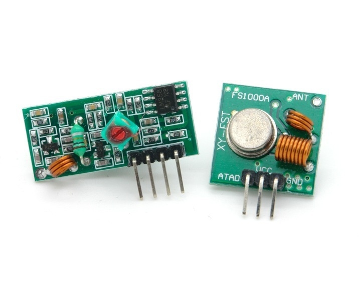
Receiver module parameters:
Product Model: XY-MK-5V
Operating voltage : DC5V quiescent current: 4mA
Receiving frequency: 433.92MHz
Receiver sensitivity: - 105dB
Size : 30 * 14 * 7mm external antenna: 32cm single core wire wound into a spiral
Technical parameters of the transmitter head:
Product Model: XY-FS
Launch distance: 20 -200 meters (different voltage, different results)
Operating voltage: 3.5-12V
Dimensions: 19 * 19mm
Ways of working: AM
transfer rate: 4KB / S
transmit power: 10mW
Transmitting frequency: 433MHz
Blink
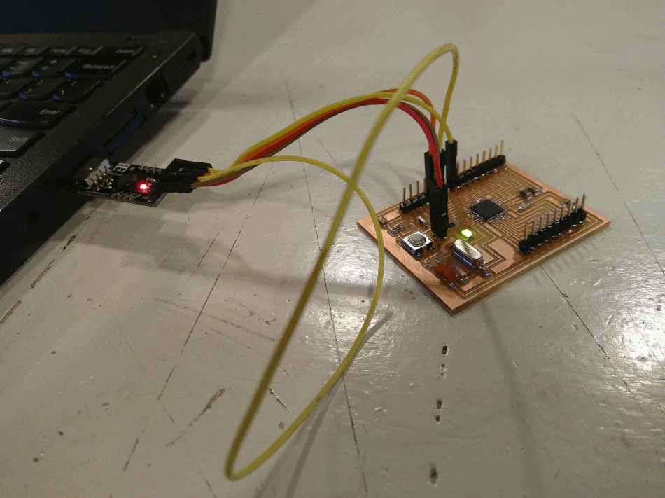
Firstly I need to test if the RF modules are working. So I used the hello world attiny boards i made during the electronics design. I used a very simple transmit and receive sketch to test their functionality. It will use the Attinys onboard LED to show when the transmitter is transmitting, and when the other Attiny is receiving. There will be a slight delay between the two Attinys. You can solder an antenna onto these modules, however I did not do this, I just kept the modules close together (1-2cm apart).
I got getting better accuracy when using 3V instead of 5V to power the receiver as described on the page were i found these arduino scripts. While using 5V for VCC on the receiver, you would get a lot of interference, however with 3V, hardly got any noise. I tested it with a ftdi that has both a 5v and 3.3v pin.
On the transmitting attiny the onboard LED illuminate when the transmitter pin is HIGH, and go off when LOW when there is no transmission.
On the receiving attiny the onboard LED should light up (and go off) at the same time as the onboard LED on the transmitting attiny.
I changed the pin number according to the attiny84 datasheet.
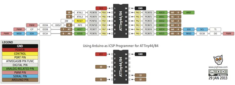
So:
 pin 0 = RX
 pin 1 = TX
 pin PA6  or MOSI = transmitting pin connected to the sender and receiver data pin
 pin 7 = ledPin
I connected the ftdi’s to the 2 hello world board. Then i used the SPI headers to connect the RF modules. I used the VCC and GND pins and as describe above and for transmitting and receiving the MOSI/PA6 pin.
Attiny Code
/*
  RF Blink - Transmit sketch
     Written by ScottC 17 Jun 2014
     Arduino IDE version 1.0.5
     Website: http://arduinobasics.blogspot.com
     Transmitter: FS1000A/XY-FST
     Description: A simple sketch used to test RF transmission.
         https://arduinobasics.blogspot.nl/2014/06/433-mhz-rf-module-with-arduino-tutorial.html
 ------------------------------------------------------------- */
#include "SoftwareSerial.h"
#define rxPin 0
#define txPin 1
SoftwareSerial serial(rxPin, txPin);
 #define rfTransmitPin PA6  //RF Transmitter pin = digital pin 4
 #define ledPin 7        //Onboard LED = digital pin 13

 void setup(){
   pinMode(rfTransmitPin, OUTPUT);
   pinMode(ledPin, OUTPUT);
 }

 void loop(){
   for(int i=4000; i>5; i=i-(i/3)){
     digitalWrite(rfTransmitPin, HIGH);     //Transmit a HIGH signal
     digitalWrite(ledPin, HIGH);            //Turn the LED on
     delay(2000);                           //Wait for 1 second

     digitalWrite(rfTransmitPin, LOW);      //Transmit a LOW signal
     digitalWrite(ledPin, LOW);            //Turn the LED off
     delay(i);                            //Variable delay
   }
 }
/*
  RF Blink - Receiver sketch
     Written by ScottC 17 Jun 2014
     Arduino IDE version 1.0.5
     Website: http://arduinobasics.blogspot.com
     Receiver: XY-MK-5V
     https://arduinobasics.blogspot.nl/2014/06/433-mhz-rf-module-with-arduino-tutorial.html
     Description: A simple sketch used to test RF transmission/receiver.
 ------------------------------------------------------------- */
#include "SoftwareSerial.h"
#define rxPin 0
#define txPin 1
SoftwareSerial serial(rxPin, txPin);
 #define rfReceivePin PA6  //RF Receiver pin = Analog pin 0
 #define ledPin 7       //Onboard LED = digital pin 13

 unsigned int data = 0;   // variable used to store received data
 const unsigned int upperThreshold = 70;  //upper threshold value
 const unsigned int lowerThreshold = 50;  //lower threshold value

 void setup(){
   pinMode(ledPin, OUTPUT);
   serial.begin(9600);
 }

 void loop(){
   data=analogRead(rfReceivePin);    //listen for data on Analog pin 0

    if(data>upperThreshold){
     digitalWrite(ledPin, LOW);   //If a LOW signal is received, turn LED OFF
     serial.println(data);
   }

   if(data<lowerThreshold){
     digitalWrite(ledPin, HIGH);   //If a HIGH signal is received, turn LED ON
     serial.println(data);
   }
 }
Networking
Sending Hello over 433Mhz with virtualwire protocol
So now in stead of blinking a led, i wanted to send something “readable”.
hello 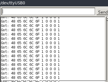
binary 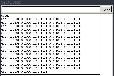
hex 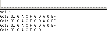
oct 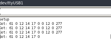
no 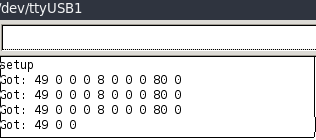
Basic networking and addressing
Arduino Virtualwire Documentation
"VirtualWire is an Arduino library that provides features to send short messages, without
addressing, retransmit or acknowledgment, a bit like UDP over wireless, using ASK
(amplitude shift keying). Supports a number of inexpensive radio transmitters and
receivers. All that is required is transmit data, receive data and (for transmitters, option-
ally) a PTT transmitter enable."
So it’s networking the old way (back in the days of coax networks). I implemented addressing like back then. Listen on the data pin, and if the first character is yours, blink the led and print to serial. If the first character is something else, do nothing.
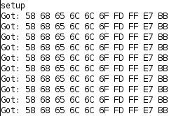
So in this case the the network address is “X” and the message “hallo”. The receiver picks up the signal, sees the “X” as a first character, followed by “hello” and prints it to serial.
With the table above you can “translate” HEX to characters.
GOT:
58 - X   <-- The network address!
68 - h
65 - e
6C - l
6C - l
6F - o
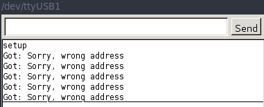
The first character is the network address. It’s a agreement between the sender and receiver. If the sender is sending to network address “X” and the receiver listens to address “Y”, the receiver will output a “wrong address” to serial.
It’s implemented in the code like this:
Sender part:
void loop(){

message="Xhello";
vw_send((uint8_t *)message, strlen(message)); // send the message
vw_wait_tx(); // Wait until the whole message is gone
delay(2000);
Receiver part:
  if (vw_get_message(buf, &buflen)) { // if message received
  Serial.print("Got: ");
    if(buf[0]=='X'){  // and if the first letter in message array is X
      digitalWrite(ledActive,LOW);
      for(int i=0;i<10;i++){        // loop alternates between LED and buzzer
        Serial.print(buf[i], HEX);
        Serial.print(' ');
        digitalWrite(ledActive,HIGH);
        delay(200);


   digitalWrite(ledActive,LOW);
        delay(200);
        }
     }
  else if(buf[0]!='X'){

  Serial.print("Sorry, wrong address");
    }
Serial.println();
}
Transmitting
//This code was written using the functions of the Virtual Wire Library.
//Function list here: http://www.airspayce.com/mikem/arduino/VirtualWire/VirtualWire_8h.html

// Code is designed for the circuit built in this tutorial: https://www.youtube.com/watch?v=gkc9xN9pZ4Y
// Written by Sanjin Dedic as a part of Robotix Arduino Tutorial Course
// http://robotix.com.au/tutorials.html


#include <VirtualWire.h>
const char *message = "hello";
int button = 3;
int ledPin = 7;

void setup() {
pinMode(button,INPUT);
pinMode(ledPin,OUTPUT);

vw_set_ptt_inverted(true); // On a communication line means that each
// party is either transmitting or receiving ( like a walkie talkie)
vw_set_tx_pin(12); // set transmitter pin
vw_setup(4000);// speed of data transfer Kbps
}

void loop(){

//if (digitalRead(button) == HIGH){
//digitalWrite(ledPin,LOW);
message="Hello";
vw_send((uint8_t *)message, strlen(message)); // send the message
vw_wait_tx(); // Wait until the whole message is gone
delay(2000);
//}
}
Receiving
#include <VirtualWire.h>
//int ledPassive = 5;  //standby light
int ledActive = 13;   //green LED's
//int buzzer = 8;


void setup()
{
 // pinMode(ledPassive,OUTPUT);
  pinMode(ledActive,OUTPUT);
 // pinMode(buzzer,OUTPUT);
  vw_set_ptt_inverted(true); // On a communication line means that each
// party is either transmitting or receiving ( like a walkie talkie)
  vw_set_rx_pin(12); // set receiver pin
  vw_setup(4000);  // Bits per sec
  vw_rx_start();       // Start Phase Locked Loop (listening to the receiver)
    Serial.begin(9600);  // Debugging only
    Serial.println("setup");
}
    void loop()
{
//  digitalWrite(ledPassive,HIGH);
 // digitalWrite(buzzer,LOW);
  //digitalWrite(ledActive, HIGH);
  uint8_t buf[VW_MAX_MESSAGE_LEN]; // 80 bytes is messgage length
  uint8_t buflen = VW_MAX_MESSAGE_LEN;

  if (vw_get_message(buf, &buflen)) { // if message received
  Serial.print("Got: ");
    if(buf[0]=='H'){  // and if the first letter in message array is X
      digitalWrite(ledActive,LOW);
      for(int i=0;i<10;i++){        // loop alternates between LED and buzzer
   //     digitalWrite(buzzer,LOW);
        Serial.print(buf[i], HEX);
        Serial.print(' ');
        digitalWrite(ledActive,HIGH);
        delay(200);
   //     digitalWrite(buzzer,HIGH);


   digitalWrite(ledActive,LOW);
        delay(200);
        }
     }
  else if(buf[0]!='H'){
 //     digitalWrite(ledActive,LOW);
  Serial.print("Sorry, wrong address");
    }
Serial.println();
}
}
Satshakit
For several reasons i decided to make 2 atmega boards. One of the reasons is that most of the code that you can find on the internet is made for the arduino uno. During the input and output weeks I but also other students had problems in getting code running on attiny’s. With a atmega board that is 100% compatible with the arduino uno i hope to have a faster development and prototyping time.
I used the Satshakit, which is is a 100% Arduino IDE and libraries compatible, fabbable and open source board, and also an improved version of Fabkit.
Main improvements and features over Fabkit are:
16Mhz instead of 8Mhz
crystal instead of resonator
costs less (7-9 euro vs 13 euro)
100% compatible with default Arduino IDE (satshakit is recognized as Arduino UNO)
ADC6/7 connected instead of ADC6/7 not connected (satshakit laser and cnc)
larger space to easy soldering (satshakit laser and cnc)
Since i’m using kicad latest version (5.0.0-rc2), i could import the eagle project from the satshakit git repository. That went without any problems.
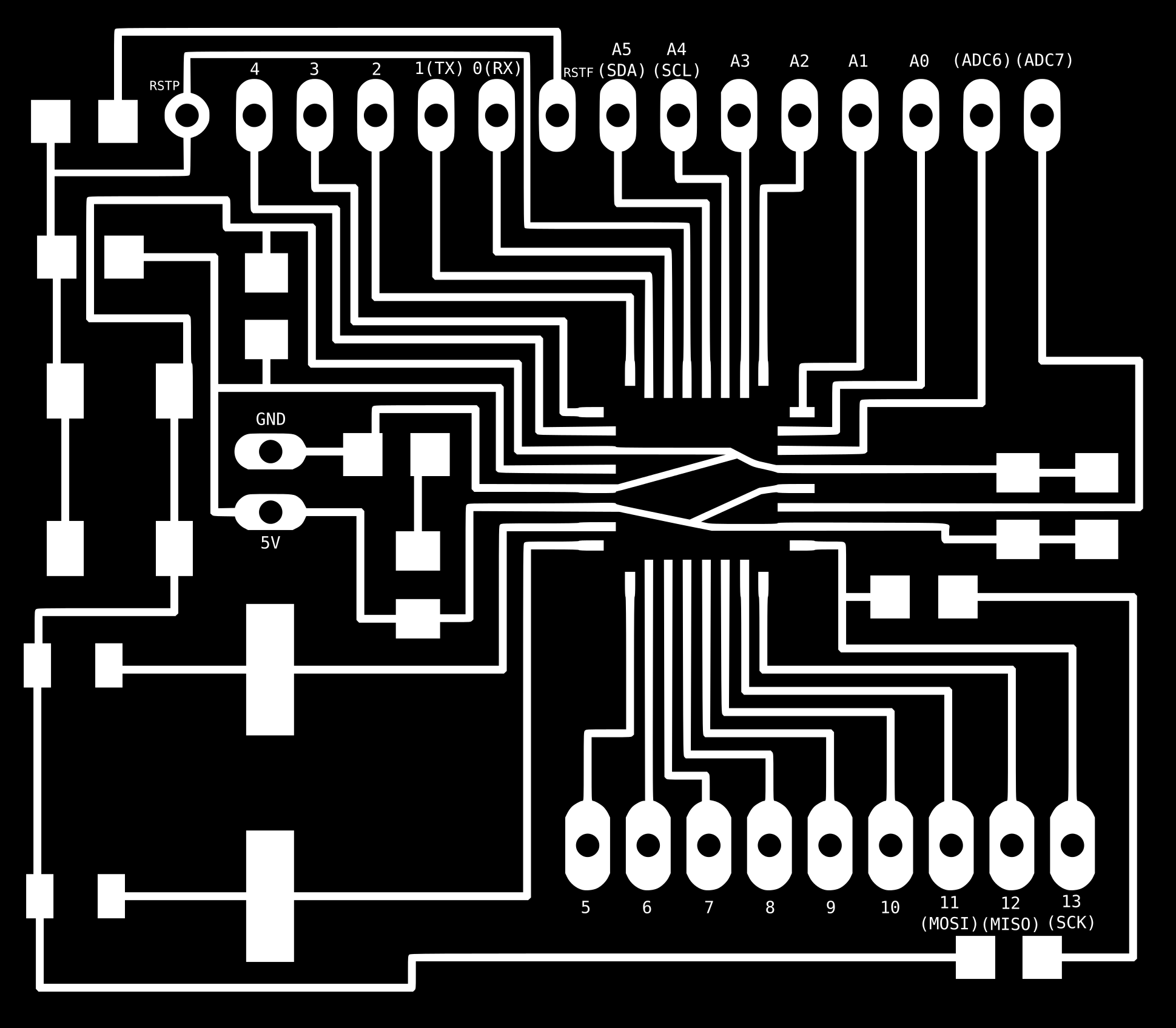
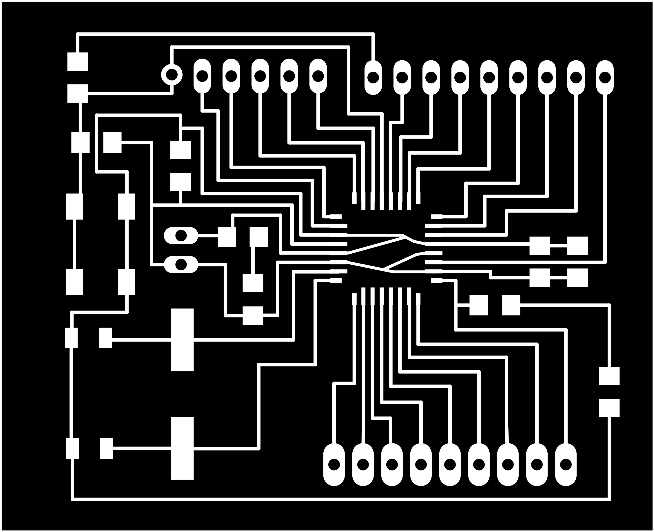
Here is the final result:
Problems and Solutions
-
exporting the design to png format
Finding the right layers to export to png took me while, but i got it done :)
-
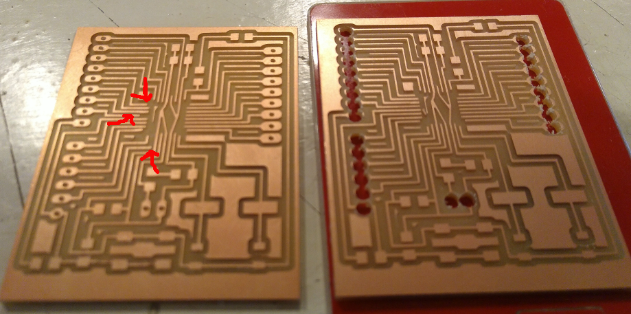
Milling the board
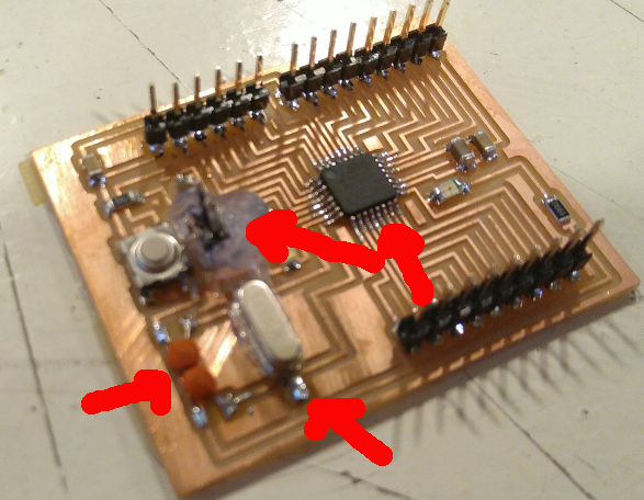
- The traces on the board are very small. They are acceptable for the modela (i used the design setting from the electronics production week. The bit from the modela knocked some ends of the small traces of the atmega (see marks picture below). Also i made a mistake milling the holes. I got the design with a black background and white dots. I should be the opposite. In molds there is an option in the file handling to invert the png.
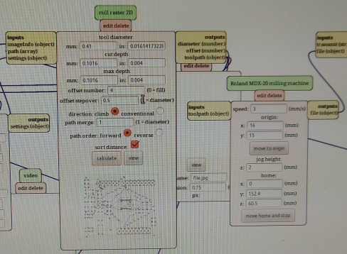
- I changed the deafult settings of mods to make new prints. The tooldiameter was made a bit bigger then the actual tool and the speed lowered to 3mm/s.
-
Soldering
We had not all components in smd, so i had to use some PTH parts: the christal and the 22pf caps. Also i made a mistake in the orientation of the atmega. Using a heatgun to unsolder the piece worked really well. I then removed most of the solder from the contacts and the islands on the board and used the heatgun again to solder the atmega in the right orientation. The power pins came loose, so i finally used hotglue to make it more stabel again.
Burning the bootloader and programming the atmega
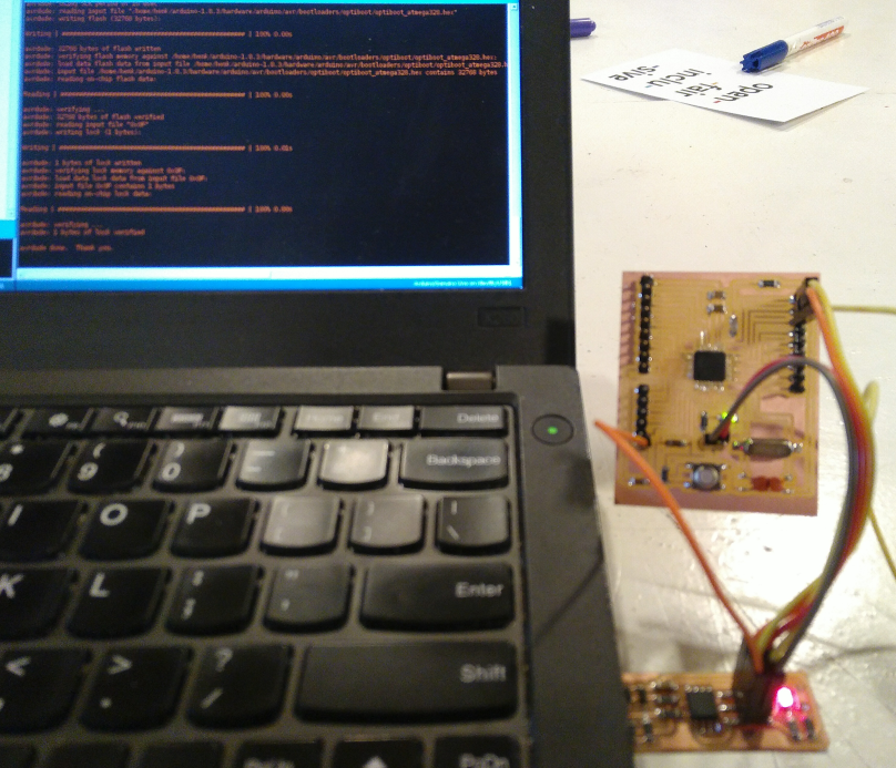
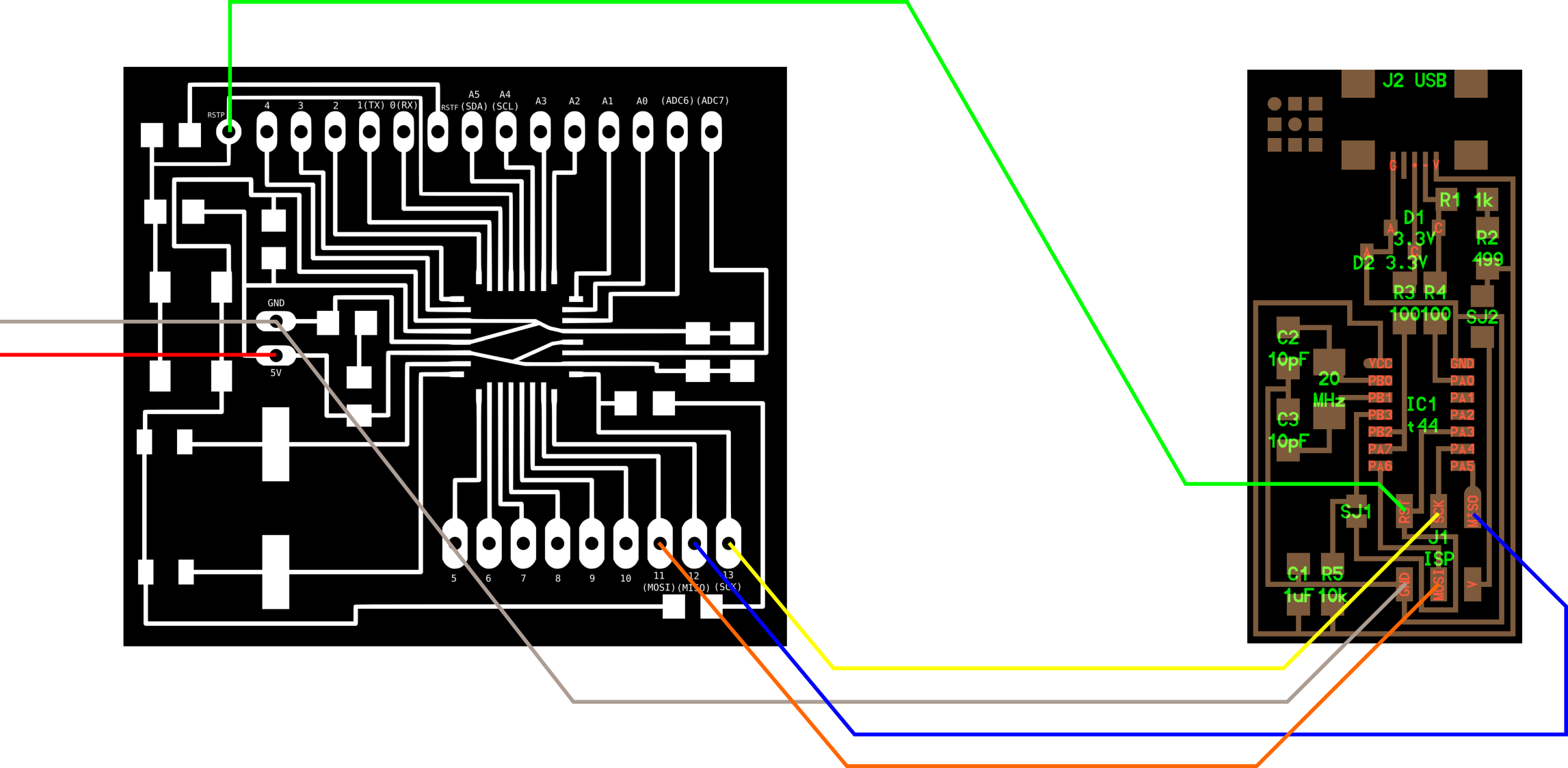
Howto connect the tinyisp to the satshakit to burn the bootloader
Howto connect the ftdi to the satshakit
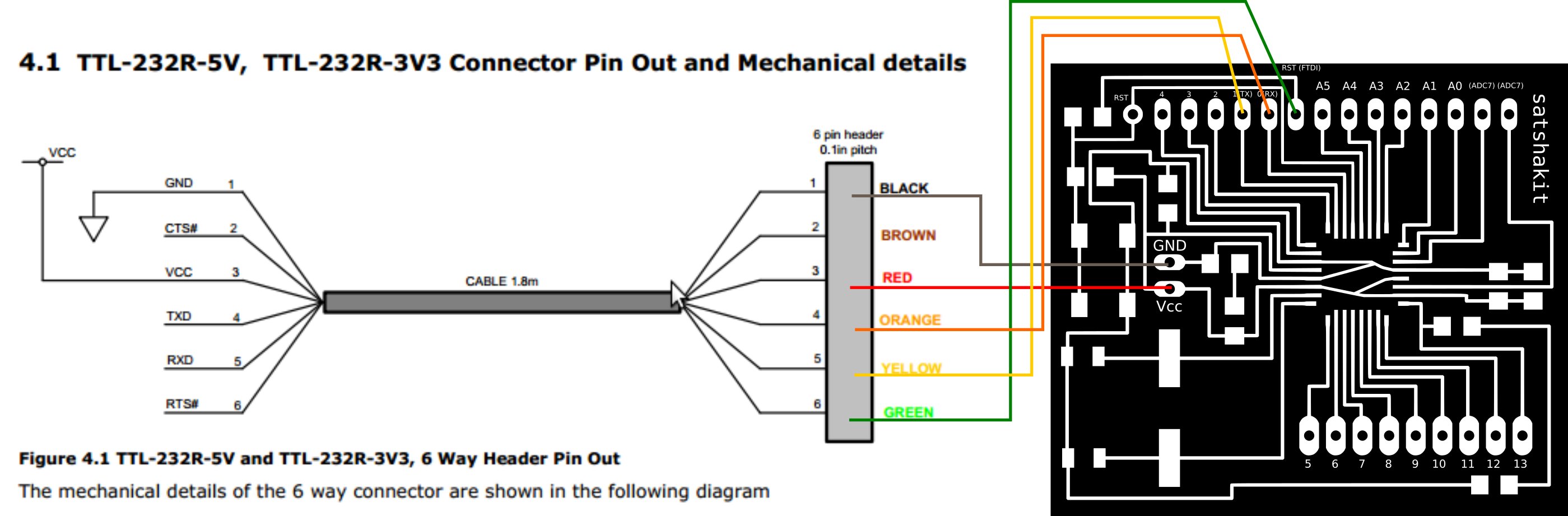
Satshakit pin mapping