| This week | |
|---|---|
| Presentation Embedded Programming | http://academy.cba.mit.edu/classes/embedded_programming/index.html |
| video of the review (Computer-Controlled Machining | http://fab.academany.org/2018/lectures/fab-20180307.html |
| [video of the lecture | http://fab.academany.org/2018/lectures/fab-20180307.html |
| video of the recitation on safety and security | http://fab.academany.org/2018/lectures/fab-20180319.html |
| Assignment | Used software | Files/Downloads/links |
|---|---|---|
| Group Assignment | compare the performance and development workflows for other architectures | http://fab.academany.org/2018/labs/fablabamsterdam/week9/index.html |
| button_on_off.ino | Arduino | button_on_off.ino |
Programming the hello world board
Clocks and Fuses!
Clocks
I was playing with the Oscilloscope, mainly because i think i’ve to use it for my final project (measuring ice thickness with Ultra Sone Sound).
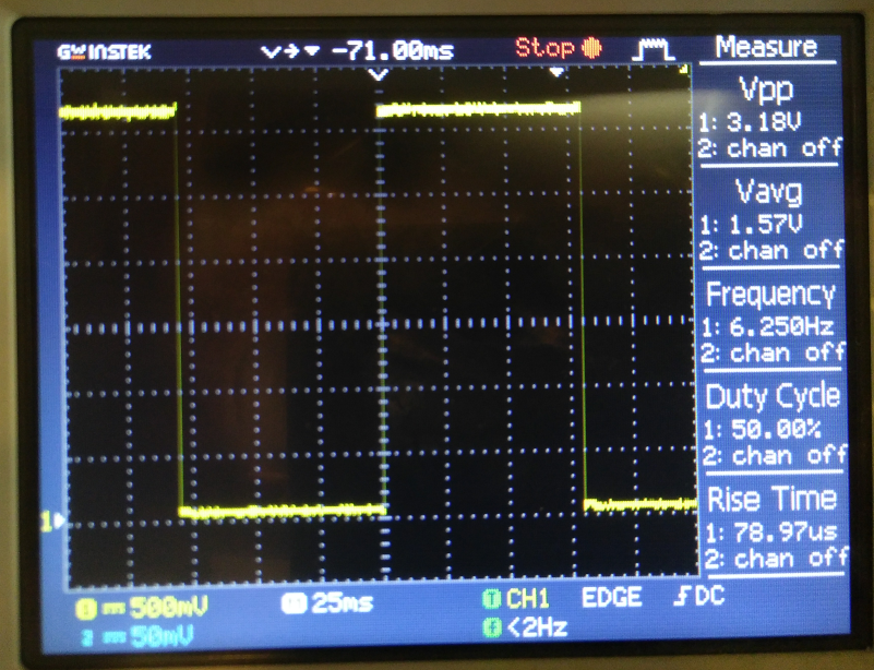
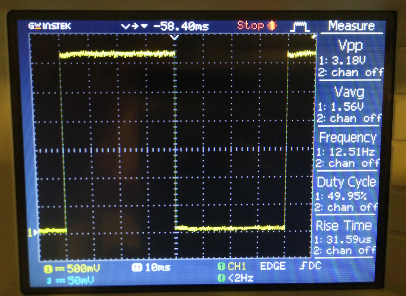
During the local lecture Emma showed us the oscilloscope. Connecting one pin to GND and the other to the LED, we could see the timing of the LED (see the group assignment). We noticed a slightly longer signal on the oscilloscope, around 110ms, instead of the 100ms that we programmed. Emma told us that it had to do the arduino-ide that we used. C has a smaller footprint and uses less resources, and should be more accurate, she told us.
Anyway: i wanted to see it myself!. So i programmed the board with the arduino-ide and C, measured both with the oscilloscope. Here are the results:
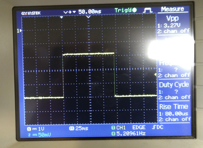
with C code
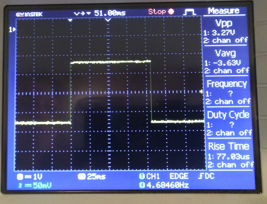
with arduino code
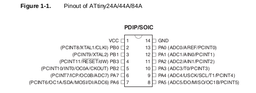
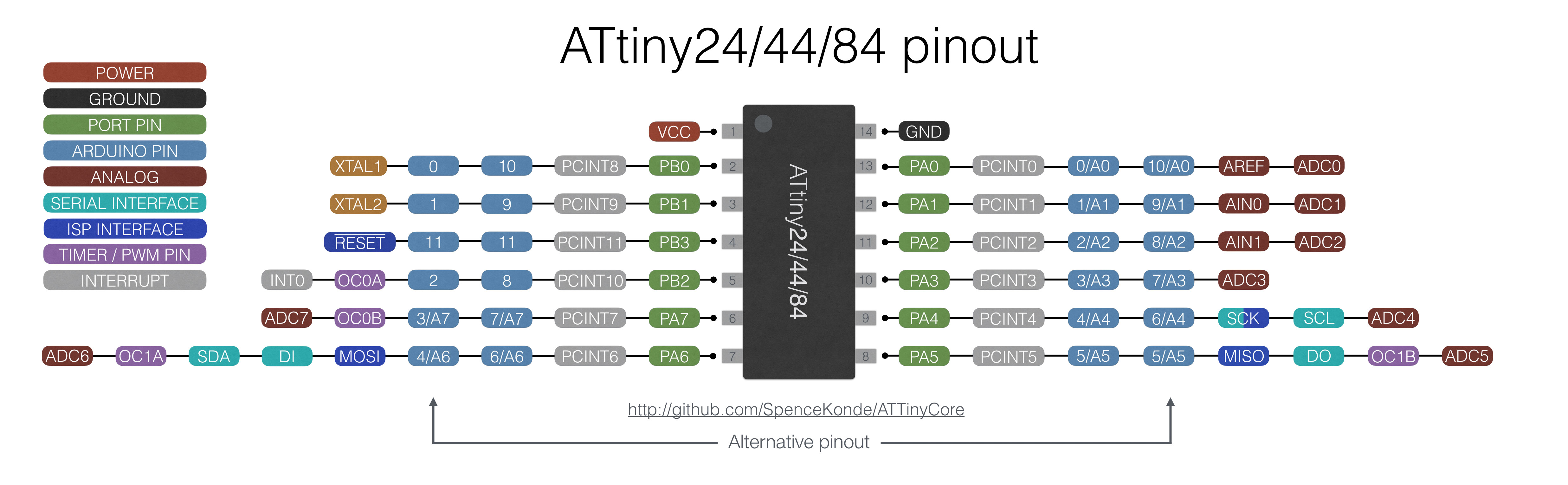
Emma mentioned that it would also be nice to measure the clock, so we went to the attiny84 datasheet. Page 24-32 handles the clock system. The clock subsystems contains:
- CPU clock
- I/O clock
- Flash clock
- ADC clock
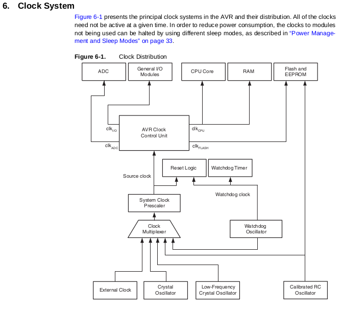
Anyway: here it gets interesting:
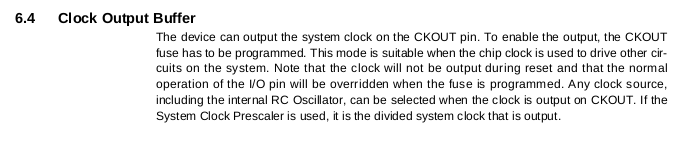
So that means that we could get a visual of the clock by the oscilloscope. In the attiny pinout diagram we figured out that it has to be PB2:
Fuses
So according to the datasheet i have to set the fuse.
safemode: Fuses OK (E:FF, H:DF, L:E2)
Howto not to do it:
first read the status of the fuse:
avrdude -p t84 -P usb -c usbtiny -U lfuse:r:-:h
Then i decided to trun the of and after that enable the fuse i need for routing the clock to PB2
avrdude -p t84 -P usb -c usbtiny -v -U lfuse:w:0x00:m
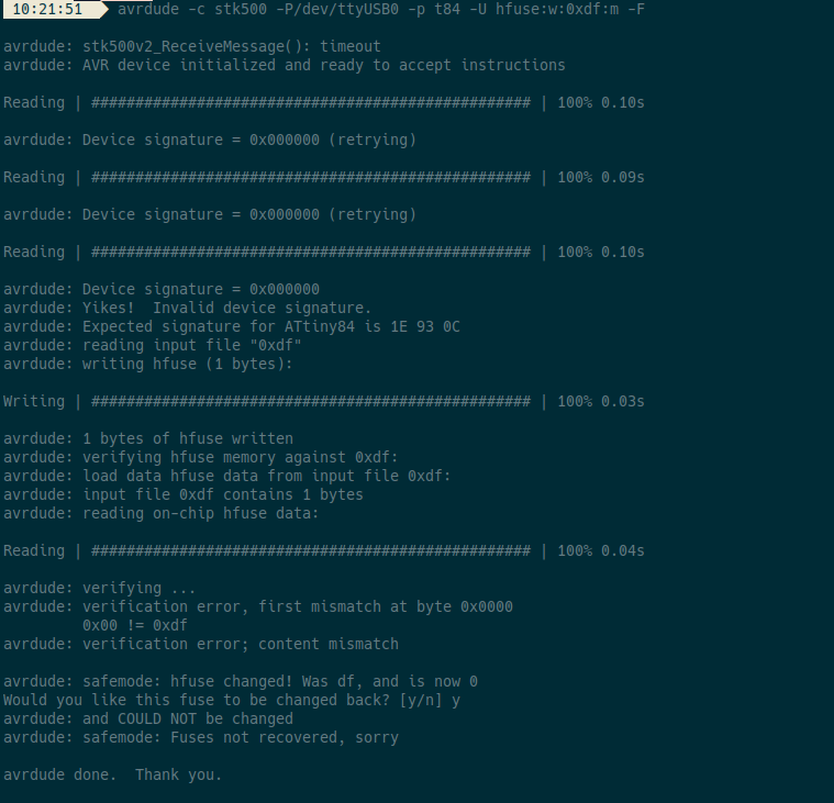
It was a major victory. It worked as i expected, BUT… By disabling the fuse i also disabled the clock! And without a clock, the avr stop functioning. It took a while for me to understand, but now it seems logical that i bricked my attiny84 on purpose…
I started reading about fuses here (adafruit: what is a fuse) and here (Fabacademy: Understanding Fuses)
Be careful when experimenting with fuses as I bricked one of my boards. There seem to be ways to reset the fuses to factory settings, e.g. through the High Voltage Serial Programming (HVSP) interface, but usually replacing the chip is a cheaper and quicker method.
Fuses are an extremely important part programming a chip, but are rarely explained thoroughly. You only need to set them once, but if you don’t do it right, it’s a disaster!
What is a fuse?
You know about flash, eeprom and RAM as parts of the chip. What I did not mention is that there are also 3 bytes of permanent (by permanent I mean that they stick around after power goes out, but that you can change them as many times as you’d like) storage called the fuses. The fuses determine how the chip will act, whether it has a bootloader, what speed and voltage it likes to run at, etc. Note that despite being called ‘fuses’ they are re-settable and dont have anything to do with protection from overpowering (like the fuses in a home).
The fuses are documented in the datasheets, but the best way to examine the fuses is to look at a fuse calculator such as the avr fuse calculator from the palmavr project
</I>
Topic: Help supply clock signal from Arduino (to debrick AVR)
Recovering from a “locked out” AVR
Possible solution is use an external clock from another source.
- an STK500. This has an on-board clock circuit. In AVR Studio, when you connect to the STK500, you can program this clock to some division of 3.6864MHz
- an STK600 has a very similar clock circuit though its upper frequency limit is higher than the STK500
- an NE555 can easily be wired up with a handful of components to generate about 1MHz
- another AVR can be used if you load a program such as:
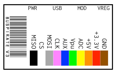
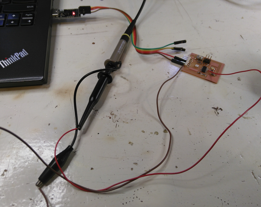
Since i had 2nd hello world board i went for option 4. And i used a buspirate flashed with stk500-v2 avr programmer firmware, mainly because it was also mentioned as an option.
using a buspirate to program the board
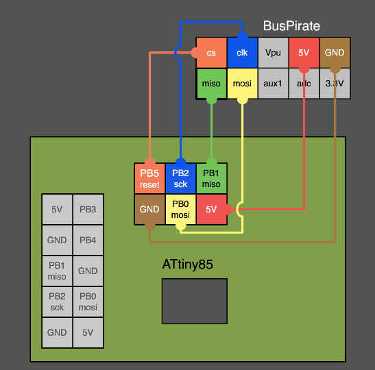
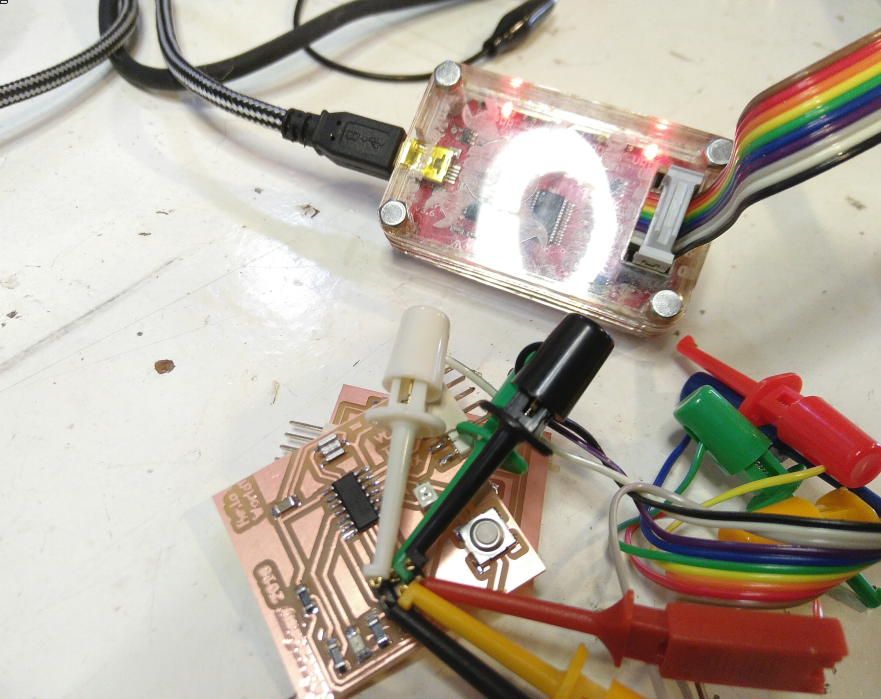
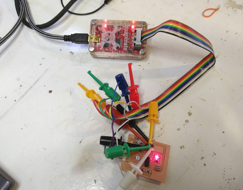
Using external clock to program a bricked AVR
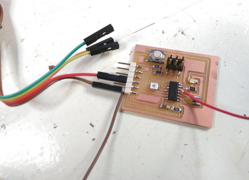
programmed the working hello world board with this:
it pulses as fast as it can, so is like a clock. I tried to see differences when using the different clock speeds. I used the arduino-ide to do this using the bootloader.
#include <avr/io.h>

int main(void) {
    DDRB = 0xFF;
    while(1) {
        PORTB ^= 0xFF;
    }
}
This is the pulse i get from PB2 now:
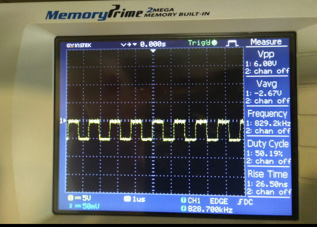
connecting oscilloscope to the clock i wanted to use
it was a dirty job. Somewhere it looked like something worked.
avrdude -p t84 -c usbtiny -U lfuse:w:0x6A:m -U hfuse:w:0xFF:m -B250

avrdude: AVR device initialized and ready to accept instructions

Reading | ################################################## | 100% 0.06s

avrdude: Device signature = 0x1e930c (probably t84)
avrdude: reading input file "0x6A"
avrdude: writing lfuse (1 bytes):

Writing | ################################################## | 100% 0.06s

avrdude: 1 bytes of lfuse written
avrdude: verifying lfuse memory against 0x6A:
avrdude: load data lfuse data from input file 0x6A:
avrdude: input file 0x6A contains 1 bytes
avrdude: reading on-chip lfuse data:

Reading | ################################################## | 100% 0.02s

avrdude: verifying ...
avrdude: 1 bytes of lfuse verified
avrdude: reading input file "0xFF"
avrdude: writing hfuse (1 bytes):

Writing |                                                    | 0% 0.00s ***failed;
Writing | ################################################## | 100% 0.16s

avrdude: 1 bytes of hfuse written
avrdude: verifying hfuse memory against 0xFF:
avrdude: load data hfuse data from input file 0xFF:
avrdude: input file 0xFF contains 1 bytes
avrdude: reading on-chip hfuse data:

Reading | ################################################## | 100% 0.02s

avrdude: verifying ...
avrdude: verification error, first mismatch at byte 0x0000
         0xdf != 0xff
avrdude: verification error; content mismatch

avrdude: safemode: hfuse changed! Was ff, and is now df
Would you like this fuse to be changed back? [y/n] y
avrdude: safemode: and is now rescued
avrdude: safemode: Fuses OK (E:FF, H:FF, L:6A)

avrdude done.  Thank you.
Since then there is a clock functioning somewhere on the chip. If i power the board trough the fabisp, the led blinks when i am trying to program it, simultaneous to the led on the fabisp.
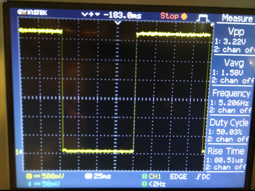
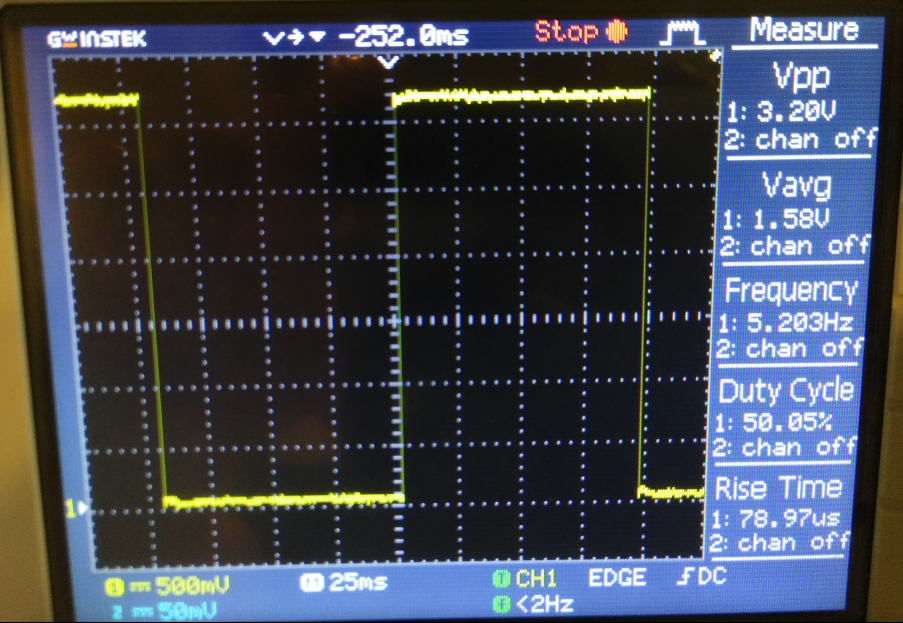
Oscilloscope adventures
What is did was the following:
- Burning the bootloader with different clock settings:
- Uploading the hello_digital sketch
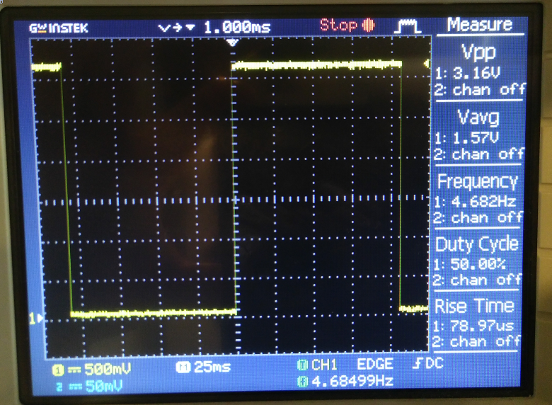
- measuring the LED with the oscilloscope
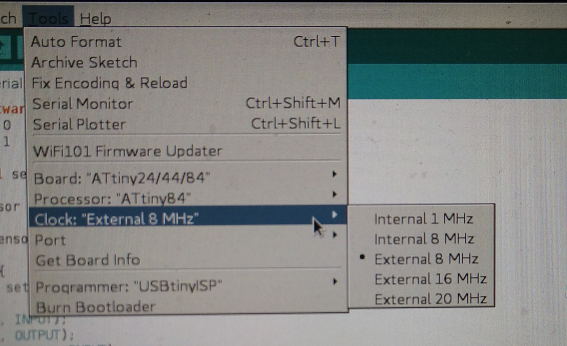
1Mhz internal clock
8Mhz internal clock
8Mhz external clock
16Mhz external clock
20Mhz external clock
One conclusion of the measurements is that the internal clock of the attiny is less accurate then the external 20Mhz resonator on our hello world board.
Programming in arduino-ide (or NOT!)
I programmed the board with the arduino-ide, version 1.8.5.

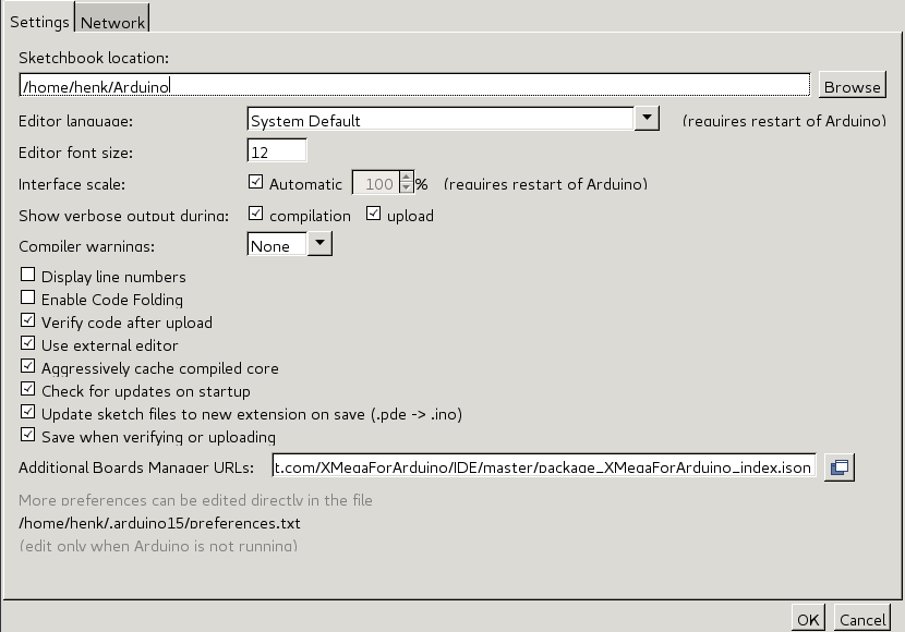
I use vim as external editor. Its a setting you can select under “file” –> “preferences” in the arduino-ide. Once selected you can’t use the arduini-ide editor anymore, its greyed out. You now can edit the file with your favorite editor and every time the file is written to the FS, the arduino file-buffer is updated. So you can still use the other functions from arduino ide like “verify”, “upload” and select boards and ports.
So the workflow is:
- open arduino-ide
- open file in ide
- open terminal
- open file in vim
- edit file in vim
- write file or close
- if needed change port and board setting
- verify code in the arduino-ide
- upload code
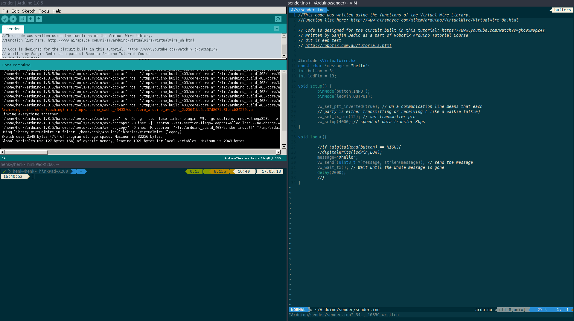
My screen looks like this:
While busy with the fabacademy and researching how to make better use of vim and arduino, i found this page on vim + arduino. It handles about using makefiles to avoid the workflow on editing and uploading in separate environments. Played a bit with and its nice if vim is your primary editor. Compiling Arduino sketches using Makefile. No need to leave vim, no need to switch to the arduino-ide window. And less noise on the computer screen :-)
It’s also possible to program the attiny this way. Place the Makefile in the same directory as the ino file. From within vim, use :make :make ispload to compile/verify or upload the sketch to the board. :make monitor opens the serial, but that only works when compiling for the Arduino with ftdi or other usb2serial connection.
The Makefile looks like this:
# Arduino Make file. Refer to https://github.com/sudar/Arduino-Makefile

# Set this if the IDE is not in your $PATH or you want to use a specific version:
ARDUINO_DIR = $(HOME)/arduino-1.8.5

# Programmer type:
ISP_PROG = usbasp

ALTERNATE_CORE = attiny-master
BOARD_TAG = attiny
BOARD_SUB = attiny85
F_CPU = 16000000L

# Path to the Arduino Makefile
include /usr/share/arduino/Arduino.mk

# !!! Important. You have to use 'make ispload' when using an ISP.
It also includes a python script to generate Makefiles:
usage: ardmk-init [-h] [-v] [-d DIRECTORY] [-b BOARD] [-u MICRO] [-f FREQ]
                  [-p PORT] [-n NAME] [--cli] [-P] [-t] [-V]

Arduino Makefile and boilerplate project generator. For use with Ard-Makefile:
https://github.com/sudar/Arduino-Makefile. Script created by John Whittington
https://github.com/tuna-f1sh 2017 Version: 1.1

optional arguments:
  -h, --help            show this help message and exit
  -v, --verbose         print file contents during creation
  -d DIRECTORY, --directory DIRECTORY
                        directory to run generator, default cwd
  -b BOARD, --board BOARD
                        board tag
  -u MICRO, --micro MICRO
                        microcontroller on board
  -f FREQ, --freq FREQ  clock frequency
  -p PORT, --port PORT  monitor port
  -n NAME, --name NAME  project name
  --cli                 run with user prompts (requires "Clint" module),
                        rather than args
  -P, --project         create boilerplate project with src, lib and bin
                        folder structure
  -t, --template        create bare minimum Arduino source file
  -V, --version         show program's version number and exit
Programming
Fascinating to see on how many ways you can program the same. I wanted to use the button to switch the led on or off. So it needed tot remember or question the current or last state of the led.
I started with this code and modified it to be used on my board.
First changed the main int settings according to my hello world board (ledpin = 7, button pin = 3). The lastButtonState is set to HIGH, the default state on my board.
Then in the setup function (void setup) i wrote the pin modes. The ledpin as OUTPUT, the buttonpin as INPUT_PULLUP. It monitors the state of the switchbutton. On my hello world board the state is HIGH. When the switchbutton is pushed (make a connection to GND, the state changes to LOW.
Then the programs function loop starts. It grabs the currentButtonState by reading the state of the buttonPin. If the state has changed (currentButtonState == HIGH && lastButtonState == LOW) it changes the state of the ledPin (if read 1, then write 0 == OFF), otherwise change to 1 (ON).
Then store the buttons current state so we can tell if it’s changed next time round.
// found here: https://arduino.stackexchange.com/questions/3479/how-to-toggle-led-on-button-press

int ledPin = 7;
int buttonPin = 3;
int lastButtonState = HIGH;


void setup() {

pinMode(ledPin, OUTPUT);
pinMode(buttonPin, INPUT_PULLUP);
}

void loop()
{
  // Get the current state of the button
  int currentButtonState = digitalRead(buttonPin);

  // Has the button gone high since we last read it?
 if (currentButtonState == HIGH && lastButtonState == LOW) {
     // Switch the state of the output
    if(digitalRead(ledPin))
       digitalWrite(ledPin, 0);
    else
       digitalWrite(ledPin, 1);

  }

  // Store the button's state so we can tell if it's changed next time round
  lastButtonState = currentButtonState;
}
You can make the code a bit smaller by substitute if() else() for this:
void loop()
{
  // Get the current state of the button
  int currentButtonState = digitalRead(buttonPin);

  // Has the button gone high since we last read it?
 if (currentButtonState == HIGH && lastButtonState == LOW) {
     // Switch the state of the output
     digitalWrite(ledPin, !digitalRead(ledPin));
  }
Or make it longer commenting the code and write out everything, counting the amount of pushes and als outputing for serial communication:
/*  The circuit:
  - pushbutton attached to pin 3 from +5V
  - LED attached from pin 7 to ground
*/

// this constant won't change:
const int  buttonPin = 3;    // the pin that the pushbutton is attached to
const int ledPin = 7;       // the pin that the LED is attached to

// Variables will change:
int buttonPushCounter = 0;   // counter for the number of button presses
int buttonState = 0;         // current state of the button
int lastButtonState = 0;     // previous state of the button

void setup() {
  // initialize the button pin as a input:
  pinMode(buttonPin, INPUT);
  // initialize the LED as an output:
  pinMode(ledPin, OUTPUT);
  // initialize serial communication:
  Serial.begin(9600);
}

void loop() {
  // read the pushbutton input pin:
  buttonState = digitalRead(buttonPin);

  // compare the buttonState to its previous state
  if (buttonState != lastButtonState) {
    // if the state has changed, increment the counter
    if (buttonState == HIGH) {
      // if the current state is HIGH then the button went from off to on:
      buttonPushCounter++;
      Serial.println("on");
      Serial.print("number of button pushes: ");
      Serial.println(buttonPushCounter);
    } else {
      // if the current state is LOW then the button went from on to off:
      Serial.println("off");
    }
    // Delay a little bit to avoid bouncing
    delay(10);
  }
  // save the current state as the last state, for next time through the loop
  lastButtonState = buttonState;


  // turns on the LED every four button pushes by checking the modulo of the
  // button push counter. the modulo function gives you the remainder of the
  // division of two numbers:
  if (buttonPushCounter % 2 == 0) {
    digitalWrite(ledPin, LOW);
  } else {
    digitalWrite(ledPin, HIGH);
  }