| This week | |
|---|---|
| Presentation 3D scanning and printing | http://academy.cba.mit.edu/classes/scanning_printing/index.html |
| video of the review (Electronics Production) | http://fab.academany.org/2018/lectures/fab-20180221.html |
| [video of the lecture | http://fab.academany.org/2018/lectures/fab-20180221.html |
| video of the recitation on Maker Education | http://fab.academany.org/2018/lectures/fab-20180226.html |
| Assignment | Used software | Files/Downloads/links |
|---|---|---|
| Group Assignment | test the design rules for your 3D printer(s) | http://fab.academany.org/2018/labs/fablabamsterdam/week6/index.html |
| solenoid.scad | OpenSCAD | solenoid.scad |
| solenoid.stl | Cura | solenoid.stl |
| hand.stl | Cura | hand.stl |
Assignment
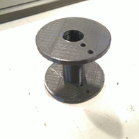
For my final assignment i need to make a solenoid. So for this assignment i want to make a spool, developed in OpenSCAD, that can be used to build a solenoid (aka electromagnet) with enameled copper wire.
The spool is a fairly simple shape, so i discussed with Emma (our local mentor) if it would be enough for this assignment. We ended up agreeing that it is, because we cannot make this spool on another machine. With the shopbot we could have done a fair amount, if we had a rotary module for the cnc. If we had one, the spool could have been drilled with the CNC and at the end making the wire holes with a drill, but we unfortunate don’t have one.
And specially: it’s fit’s in my list of todo’s for the final project. So the 3D model and print are going to be a spool, to make a solenoid.
OpenSCAD or 3d scripting
From wikipedia:
A solenoid (/ˈsoʊ.lə.nɔɪd/)[1] (from the French solénoïde, derived in turn from the Greek solen ("pipe, channel") and eidos ("form, shape")[2]) is a coil wound into a tightly packed helix. The term was invented by French physicist André-Marie Ampère to designate a helical coil.[3]

In physics, the term refers to a coil whose length is substantially greater than its diameter, often wrapped around a metallic core, which produces a uniform magnetic field in a volume of space (where some experiment might be carried out) when an electric current is passed through it. A solenoid is a type of electromagnet when the purpose is to generate a controlled magnetic field. If the purpose of the solenoid is instead to impede changes in the electric current, a solenoid can be more specifically classified as an inductor rather than an electromagnet. Not all electromagnets and inductors are solenoids; for example, the first electromagnet, invented in 1824, had a horseshoe rather than a cylindrical solenoid shape.

In engineering, the term may also refer to a variety of transducer devices that convert energy into linear motion. The term is also often used to refer to a solenoid valve, which is an integrated device containing an electromechanical solenoid which actuates either a pneumatic or hydraulic valve, or a solenoid switch, which is a specific type of relay that internally uses an electromechanical solenoid to operate an electrical switch; for example, an automobile starter solenoid, or a linear solenoid, which is an electromechanical solenoid. Solenoid bolts, a type of electronic-mechanical locking mechanism, also exist.
I decided to use openSCAD because i think its a better tool to make the spool, and i wanted to learn also another (opensource) tool next to freeCAD.
OpenSCAD is not an interactive modeller. Instead it is something like a 3D-compiler that reads in a script file that describes the object and renders the 3D model from this script file. This gives you (the designer) full control over the modelling process and enables you to easily change any step in the modelling process or make designs that are defined by configurable parameters.
Solenoid spool parametric script for OpenSCAD
While looking for examples and documentation i found an ready to use openscad parametric script to make a solenoid spool. So what i’m going to do next is modifying and rewriting the script and commenting what it is doing.
The script is only 34 lines long (without comments), and you can change all parameters in one line.
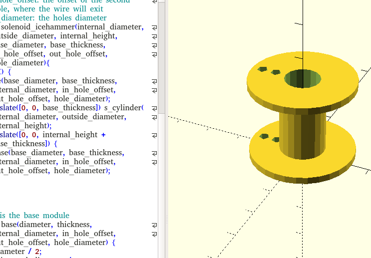
So first: here is the script:
// Author: Emanuele Caruso (caru)
// License: Creative Commons - Attribution-ShareAlike 3.0 United States (CC BY-SA 3.0) (http://creativecommons.org/licenses/by-sa/3.0/us/)

// This is the main solenoid module
//
// Parameters:
// i_diameter: the internal (core) diameter
// o_diameter: the outer diameter, on which the solenoid will be twisted
// i_height: the internal height between bases
// base_diameter: the bases diameter
// base_thickness: the thickness of the bases
// in_hole_offset: the offset of the first hole, where the wire will enter
// out_hole_offset: the offset of the second hole, where the wire will exit
// hole_diameter: the holes diameter
module solenoid(i_diameter, o_diameter, i_height, base_diameter, base_thickness, in_hole_offset, out_hole_offset, hole_diameter){
  union() {
    base(base_diameter, base_thickness, i_diameter, in_hole_offset, out_hole_offset, hole_diameter);
    translate([0, 0, base_thickness]) s_cylinder(i_diameter, o_diameter, i_height);
    translate([0, 0, i_height + base_thickness]) {
      base(base_diameter, base_thickness, i_diameter, in_hole_offset, out_hole_offset, hole_diameter);
    }
  }
}

// This is the base module
module base(diameter, thickness, i_diameter, in_hole_offset, out_hole_offset, hole_diameter) {
  r = diameter / 2;
  i_r = i_diameter / 2;
  h_r = hole_diameter / 2;
  difference() {
    cylinder(thickness, r, r);
    translate([0, 0, -1]) cylinder(thickness + 2, i_r, i_r);
    translate([-in_hole_offset, 0, -1]) cylinder(thickness + 2, h_r, h_r);
    translate([-out_hole_offset, 0, -1]) cylinder(thickness + 2, h_r, h_r);
  }
}

// This is the spool cylinder
module s_cylinder(i_diameter, o_diameter, i_height) {
  o_r = o_diameter / 2;
  i_r = i_diameter / 2;
  difference() {
    cylinder(i_height , o_r, o_r);
    translate([0, 0, -1]) cylinder(i_height + 2, i_r, i_r);
  }
}

// An example to test the design
solenoid(14, 18, 50, 50, 4, 12, 20, 4);
Basics of OpenSCAD
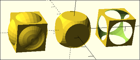
To get a better understanding of openscad, I first looked at some sample script that are under the openscad “File” –> “Examples” menu. I took the first one, because it shows the strength and easiness of this tool.
I used the openscad sheetcode to get a better understanding of the script.
- Translates (moves) its child elements along the specified vector.
- union, intersection and difference are 3 boolean operations
- Cube is a primitive solids. It creates a cube in the first octant. When center is true, the cube is centered on the origin.
- Sphere is another primitive solid
So what this script does is creating 3 boolean operations with a cube and a sphere, namely a union, a intersection on different specified vectors. Simple as that!
translate([-24,0,0]) {
    union() {
        cube(15, center=true);
        sphere(10);
    }
}

intersection() {
    cube(15, center=true);
    sphere(10);
}

translate([24,0,0]) {
    difference() {
        cube(15, center=true);
        sphere(10);
    }
}
variables and values
I then went back to the solenoid script and translated the it from variables to values (so now it’s not parametric anymore), so you don’t give the values in the last line. Doing this it was easier to modify the values in a certain part of the script to understand what it was doing.
module solenoid_icehammer(internal_diameter, outside_diameter, internal_height, base_diameter, base_thickness, in_hole_offset, out_hole_offset, hole_diameter){
  union() {
    base(30, 2, 10, 8, 12, 3);
    translate([0, 0, 2]) s_cylinder(10, 13, 20);
    translate([0, 0, 20 + 2]) {
      base(30, 2, 10, 8, 12, 3);
    }
  }
}
// This is the base module
module base(diameter, thickness, internal_diameter, in_hole_offset, out_hole_offset, hole_diameter) {
  r = diameter / 2;
  i_r = 10 / 2;
  h_r = 3/ 2;
  difference() {
    cylinder(thickness, r, r);
    translate([0, 0, -1]) cylinder(thickness + 2, i_r, i_r);
    translate([-8, 0, -1]) cylinder(thickness + 2, h_r, h_r);
    translate([-12, 0, -1]) cylinder(thickness + 2, h_r, h_r);
  }
}

// This is the spool cylinder
module s_cylinder(internal_diameter, outside_diameter, i_height) {
  o_r = 13 / 2;
  i_r = 10 / 2;
  difference() {
    cylinder(20 , o_r, o_r);
    translate([0, 0, -1]) cylinder(20 + 2, i_r, i_r);
  }
}
// An example to test the design
solenoid_icehammer();
With this script i could change values and see what changed. I helped really well to understand the solenoid - spool script i’m going to use for making the spool.
So here i break down the script:
module solenoid(i_diameter, o_diameter, i_height, base_diameter, base_thickness, in_hole_offset, out_hole_offset, hole_diameter){
  union() {
    base(base_diameter, base_thickness, i_diameter, in_hole_offset, out_hole_offset, hole_diameter);
    translate([0, 0, base_thickness]) s_cylinder(i_diameter, o_diameter, i_height);
    translate([0, 0, i_height + base_thickness]) {
      base(base_diameter, base_thickness, i_diameter, in_hole_offset, out_hole_offset, hole_diameter);
    }
  }
}
This is the whole shape. The module solenoid exist of the following parameters:
- i_diameter: the internal (core) diameter
- o_diameter: the outer diameter, on which the solenoid will be twisted
- i_height: the internal height between bases
- base_diameter: the bases diameter
- base_thickness: the thickness of the bases
- in_hole_offset: the offset of the first hole, where the wire will enter
- out_hole_offset: the offset of the second hole, where the wire will exit
- hole_diameter: the holes diameter
The module exists of a union of the base, the cylinder and another base.
The two bases have the following parameters:
- base_diameter
- base_thickness
- i_diameter
- in_hole_offset
- out_hole_diameter
- hole_diameter
The s_cylinder or spool cylinder is the spool in the middle and consists the following parameters:
- i_diameter
- o_diameter
- i_height
The 2 translate variables are for the position of the bases. The first one puts the cylinder on top of the base_thickness, just above the origin. The next translate puts another base in a position on top of the bottom-base + the cylinder.
// This is the base module
module base(diameter, thickness, i_diameter, in_hole_offset, out_hole_offset, hole_diameter) {
  r = diameter / 2;
  i_r = i_diameter / 2;
  h_r = hole_diameter / 2;
  difference() {
    cylinder(thickness, r, r);
    translate([0, 0, -1]) cylinder(thickness + 2, i_r, i_r);
    translate([-in_hole_offset, 0, -1]) cylinder(thickness + 2, h_r, h_r);
    translate([-out_hole_offset, 0, -1]) cylinder(thickness + 2, h_r, h_r);
  }
}
The base module. You can read the parameters from the code like i did above. I now go further with the calculations. Because you work from the origin and place the base center on the origin the diameter is divided by 2 (/2), same as the i_diameter and the hole_diameter.
The spool has to be hollow, so you make a difference from the cylinder in the base, based on the thickness. It then also position (translate!) the 2 little holes in the base used to insert the wire.
// This is the spool cylinder
module s_cylinder(i_diameter, o_diameter, i_height) {
  o_r = o_diameter / 2;
  i_r = i_diameter / 2;
  difference() {
    cylinder(i_height , o_r, o_r);
    translate([0, 0, -1]) cylinder(i_height + 2, i_r, i_r);
  }
}
The spool module is now pretty simple to understand. It makes a difference between the height and the inside and outside diameters of the cylinder.
// An example to test the design
solenoid(14, 18, 50, 50, 4, 12, 20, 4);
This last line sums the values for the parameters you want to make of the module solenoid, in the order of the parameters found in the 1st section.
Render and exporting to stl
Ones you decided and verified the values you want to use, you have to render (using F6 or the render button). The console gives you the following output:
Compiling design (CSG Tree generation)...
Rendering Polygon Mesh using CGAL...
Geometries in cache: 9
Geometry cache size in bytes: 20088
CGAL Polyhedrons in cache: 9
CGAL cache size in bytes: 1703760
Total rendering time: 0 hours, 0 minutes, 0 seconds
Top level object is a 3D object:
Simple:        yes
Vertices:      234
Halfedges:     702
Edges:         351
Halffacets:    242
Facets:        121
Volumes:         2
Rendering finished.
Now you can export to stl using the menu “File” –> “Export”. It asks you for a place and name where to put it.
Cura
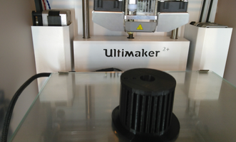
I will use the Ultimaker 2+ we have in the fablab. Therefore I first download the latest cura verion, version 3.3.1. Since I work with linux i only have to do a “chmod 755 Cura-3.3.1.AppImage” in the terminal to make cura executable.
The workorder then:
- execute Cura
- select "Ultimaker 2+" in the upper right corner.
- Load the stl file you made with OpenSCAD
- I used the default setting
- get SD card from the Ultimaker
- put it into your computer
- "save to file" and put the generated gcode on the SD card
- remove the SD card from computer and put it back into the Ultimaker.
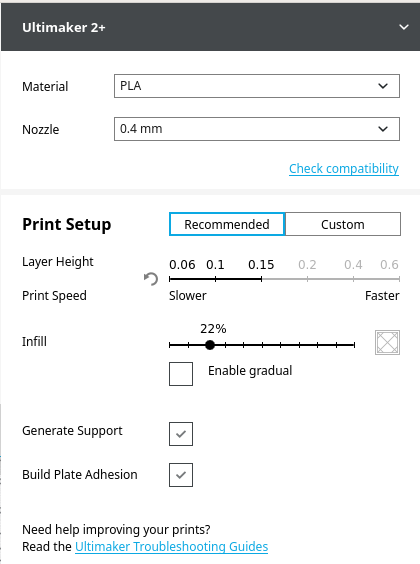
These were the recommended settings:
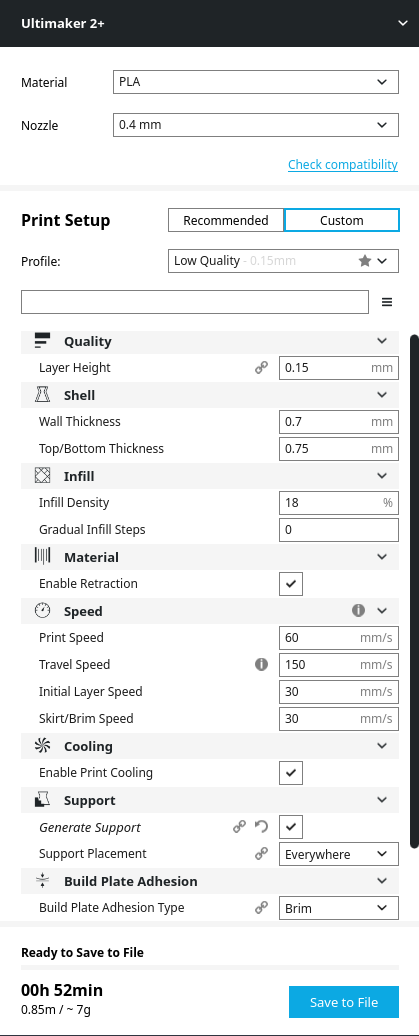
In the custom settings I added “generate support” for the upper base.
The other settings were:
- Layer Height: 0.15mm
- Wall Thickness: 0.7mm
- Top/Bottom Thickness: 0.75mm
- Infill Density: 18%
- Gradual Infill Steps: 0
- Enable Restraction
- Print speed: 60mm/s
- Travel speed: 150mm/s
- Initial Layer Speed: 30mm/s
- Skirt/Brim Speed: 30mm/s
- Enable Print Cooling
- Generate Support
- Support Placement: Everywere
- Build Adhesion Type: Brim
- Brim Width: 8mm
- Print Sequence: All at Once
Now save the file to the SD card and start working on the Ultimaker 2+.
Ultimaker 2+
- Turn on the machine
- Insert the SD card
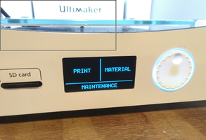
- Press Print
- Navigate to your file
- Press Accept
Calibrating the bed
I first calibrated the bed. Before doing that i cleaned it with glas cleaner. Then use the rotary wheel to go into maintenance mode.
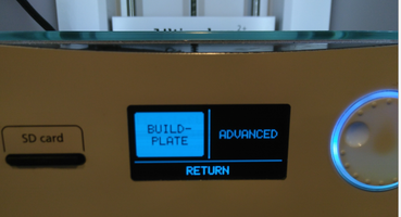
- select "build-plate"
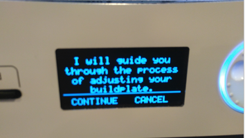
- the embedded Ultimaker software guides you through the whole process...
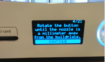
- first rotate the button to place the nozzle 1mm away from the build-plate
- then the nozzle moves to the 2 corners in the front. Use the bolds under the build plate to do the same.
- Then the ultimaker askes you to do the same with a piece of paper between the nozzle and the build plate
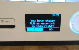
- at the end it will ask you which material you want to use, choose PLA
- ready!
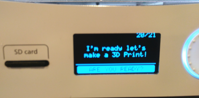
Ready to print
Change material:
- Select "change material"
- remove the PLA
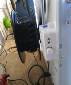
- Put the PLA of choice at the back of the Ultimaker
- Cut the start in a 45 degrees, which makes it easier for the printer for extrusion
- Insert the PLA in the back of Ultimaker
- Now feed the ultimaker with PLA till it comes out of the nozzle
- "Accept"
- Start printing!
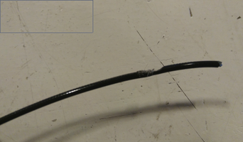
The PLA of my choice was already in the Ultimaker, so i didn’t had to change. But a strange thing happened. At the moment i started printing no PLA came out of the nozzle. So i went trough the whole “change material” with succes and again, no PLA from the nozzle.
I asked Frank (one of our local instructors) and he found out that the PLA was harmed precisely at the spot were the motor feeds the PLA to the nozzle. Solution was to cut that part of the PLA, 45 degrees en feed the Ultimaker. After that I could print.
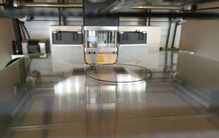
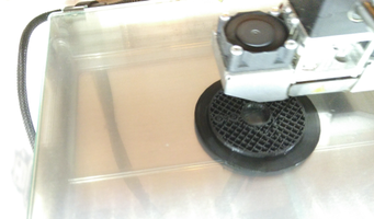
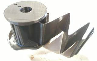
Finally i could print. So after selecting the gcode file and accepting, the nozzle started to heat up. It took a while and the head/nozzle started to move. It starts with the brim. Then the bottom base is printed, here you see a nice image of the infill. The third picture shows the support.
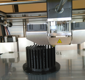
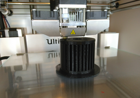
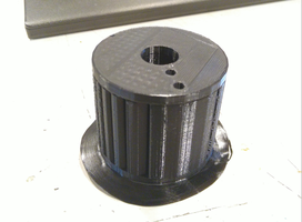
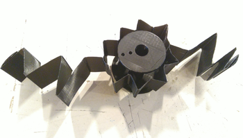
So the print was finished! It took it out and removed the brim and support. Specially the support looks funny. At the end it was a perfect spool for my solenoid.
3D scanning
It started great. First the sense, the 3d scanning device that i wanted to use for this assignment, was gone. And ones i finally found it, the software crashed. I tried installing newer versions, older versions, but nothing helped. I will try it again tomorrow, starting on another windows machine. It’s a shame. I just told Emma today, that till now, i did all my assignments with only opensource software. Because i missed the regular 3d classes, i have to do it now, at the end.
Finally! After 2 days of stuggling with the sense 3D scanner and 2 windows machines i got the damned device running. What did the trick at the end was remove the complete sense software and specially the drivers. After reinstalling it worked. Well, more or less.
I figured out that it is a tough choice to decide what to scan. Everything black/white looked hard. It also lost track during a lot of tries i did.
Emma commented that this is not completely correct: it is particularly difficult to scan shiny, transparent or extremely matte-black object. This is because such surfaces don’t reflect the IR light pattern.
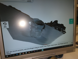
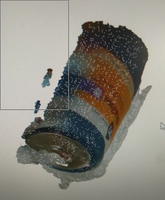
Another thing is that i figured out while scanning the muck is that it completely lost track (see image below). I was holding the scanner in 1 position and turning the muck that i had put on a big piece of white paper. Because the background didn’t change and a complete white muck with no “pattern” or “markers” is hard to reconstruct in 3d, the result was really bad.
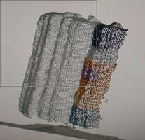
The very simple muck came out very experimental, i guess because it a to simple shape, so the software has to less “markers” or recognisable patterns. I then switch to use a battery, the only non white/black think around with at least a more complex pattern then the muck. That already gave a better image. I tried to rotate the battery on a piece of paper first.
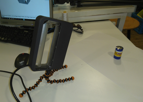
But as with the cup this turning didn’t quite work. So i did it by hand by turning the sense device around the battery. Also this didn’t work like expected. The results were more recognizable than the muck but still not something i could reproduce.
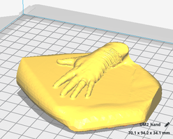
At the end, and more or less a bit hopeless i sat down, thinking what to do. It was friday, and there were no other ppl at the fablab that could help. So more or less out of pure frustration i started scanning my hand on the table. And to my surprise it, it was a nearly perfect scan!
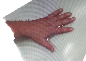
I used “solidify” to get a printable piece. Trimmed and cropped, also with the Sense software to get a nice shape around the hand.
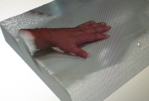
And this was the result a few minutes later…
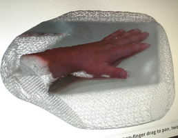
I save the hand and did a export to stl. This stl i could import to Cura. It was off course way to big, so in cura it’s scaled to 20%.
It proves i scanned a 3d object and created an printable with it.
This is the last assignment i had to do for fabacademy (and my last assignment documentation!). From now on i will completely focus on my final project.