| Assignment | Used software | Files/Downloads/links |
|---|---|---|
| casing outside | FreeCAD | case.fcstd |
| casing inside | Inkscape | case_left_inside_pockets.svg |
| piezo molds | FreeCAD | piezo_molds.stl |
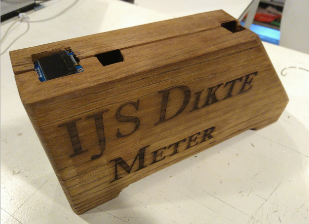
The housing for the final Project
- craft, design and appearance
So, from the beginning i wanted my project to have a crafty, old, non techy appearance. I will use re-used wood for my casing, and from the outside only the oled display and the usb-connection for charging the batterys, betrays the existence of the electronics inside.
Besides for the look and feel the decisions made for the design were:
-
electronics inside the case to make the device more robust and easy to operate for people without any knowledge. All components were screwed into the wood, so it is very solid. Wiring is done with flatcables and 4 and 6 pin connectors, so they have a tight connection to the boards.
-
oled on top to make it easier readable while operating
-
usb connector on the back of the device: most obvious place where you will look how to charge the device.
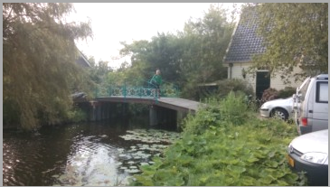
- bridge and skating tour
The wood! A couple of years ago i replaced the old bridge in front of our house. The shelves of the bed were old, the construction on top of the drawbridge was coming down because of the decaying of the wood. This “traditional” drawbridge construction didn’t work anymore and we didn’t allow cars to pass the bridge because it is small and unstable.
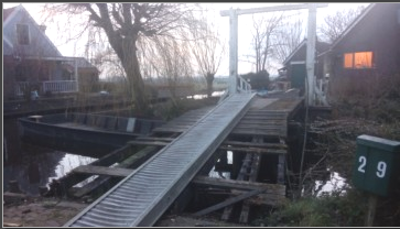
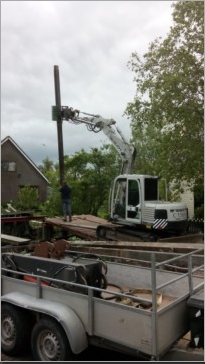
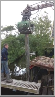
The bridge itself was build in the beginning of the ’70s. We deceided to take everything down and also replace or add extra piles, as you can see the waterlevel is only a few cm under groundlevel, so very moisty. The shelves from the bridge i denailed and stored the useable shelves. But there were also a lot of shelves that were unusable, to many nails, to much decaying, so i shopped the shelves in pieces for later use at the woodpile.
The other story of the bridges in our community is that many bridges that have been replaced lately are being a pain in the ass for watertourism like canoeing, boating and also skating. Those bridges are often replaced by new straight bridges, so you can’t skate or canoe under it. This is of big problems when we organize “tourschaatsen”, because we have to carpet the surroundings to bypass those bridges.

- wenge wood
So i found some left over shelves on the woodpile that i wanted to use for my final project. My collegue Ruud thought it is wenge wood. Working with it on the shopbot is a thingie, because “the dust produced when cutting or sanding wenge can cause dermatitis similar to the effects of poison ivy and is an irritant to the eyes. The dust also can cause respiratory problems and drowsiness.[citation needed] Splinters are septic”
Therefore to avoid the dust as much as possible i opened the windows, had glasses on and also started to wear a mouthcap. The later i didn’t use all the time, because it was anoying and impractical. I also am not sure if the wood that i used at the end was also wenge wood. It looked different from the wood that i used in the beginning. The wood on the bridges were mostly residual material, so often a mixture of hard wood that were reused.
But anyway: the wood came from our old bridge and and i liked the appearance for the casing.
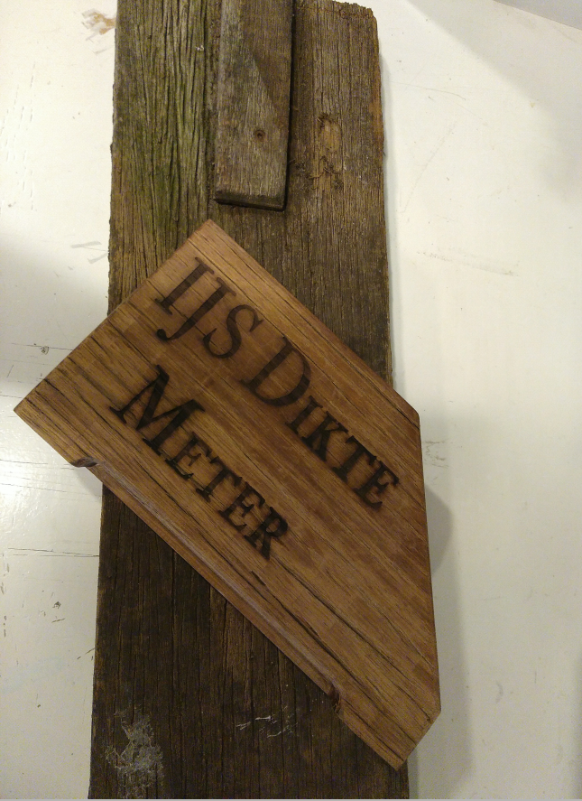
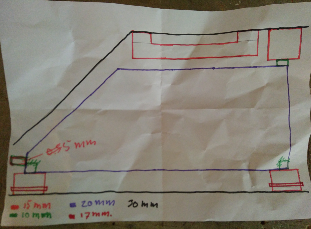
- design
The design should be very simpel. I would like to make this device with a lived, antique appearance. So besides the choise of wood for the nice story of the bridges and tour iceskating, this was also a reason for chosing this wood.
At first i wanted to use a solenoid for generating the impuls, but after some test is was clear that there is a big impuls difference between a solenoid and a hammer. So i had to change that in the design. I now want to make a hammer, outside, in front of the case. If possible from black metal, a nice welded job, but i guess i’m not finishing that before the final presentation.
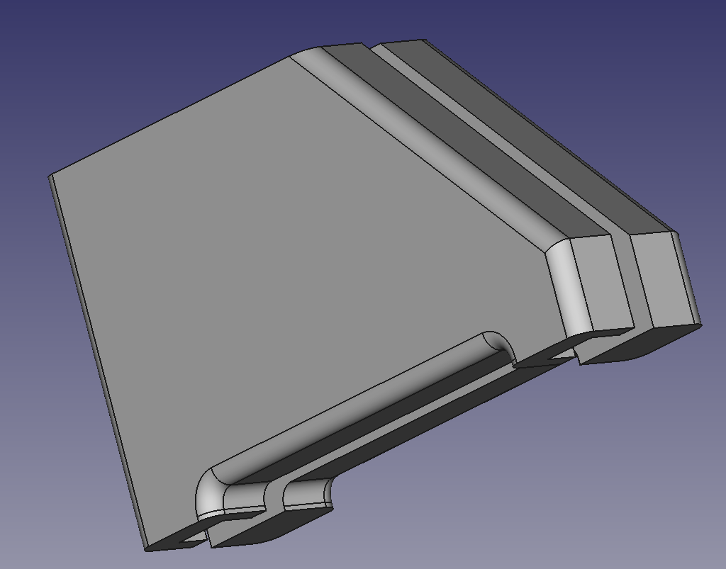
- freecad or inkscape
Well freecad… I still have a hard time to understand the workflow of designing in FreeCAD. But because of learning purposes, i decided to start in FreeCAD. And yes, it partly worked :)
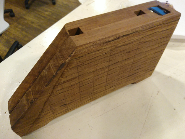
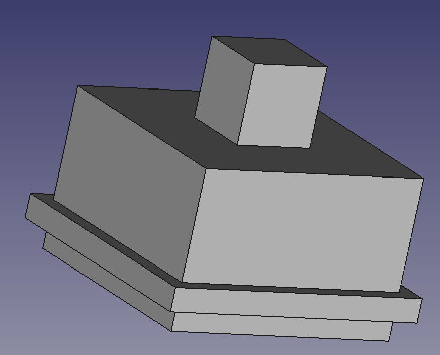
I made the design for the outside of the case in FreeCAD and could export it to an stl file.
For the inside of the case i used inkscape, because it are actually a bunch of pockets. So this decision was made because of time managment. It works faster for me…. I thought! More Later!.
CNC
When i’m writing this down, i’m still in the middle of the milling of the case. To put it nicely: I learned a lot about the shopbot. What could go wrong, went wrong. An overview what i did the last couple of days:
But first a picture:
Surfacing the shelfs
Before i could actually mill the wood, i surfaced both sides to get a flat and equal thick piece of wood. I had 2 shelfs that measured about 800x200x36 mm. I used a 2 flute 2 Inch bit to make a flat surface.
| setting for surface | |
|---|---|
| diameter tool | 2 inches |
| pass dept | 2 mm |
| stepover | 1 inch / 50% |
| spindle speed | 14000 rpm |
| feed rate | 20 mm/s |
| plunge rate | 2 mm/s |
| ToolPath settings | |
|---|---|
| start dept | 0.0mm |
| cut dept | 2.0mm |
| clear pocket | raster |
| cut direction | climb |
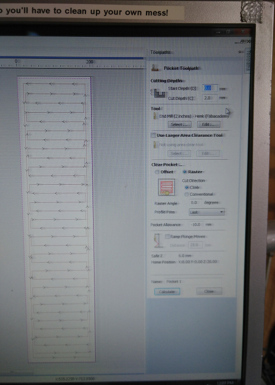
About these settings: I searched the internet about howto deal with a 2inch drill on the shopbot. The shopbot is actually one of the machines that i threat with respect. And with a 2 inch drill it becomes a monster. So i checked, double checked, and asked around till i was sure of myself how to proceed.
Anyway: the flattening of the wood went fine!
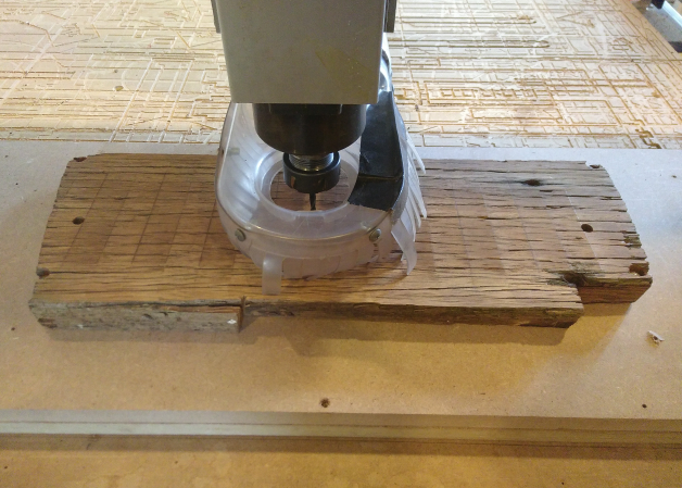
double sided 3d milling on the shopbot
I had 2 pieces of wood from my old brigde, about 200-800-34mm. I wanted to mill the outside of the case first, flip the wood, and than mill the pockets on the other side. Therefore i needed a construction, that keeps the wood in the right position. I looked at the video of former waag intern Ismael where he is milling wooden Amsterdam Icons using a fixed plate on the artificial layer of the shopbot, with 2 metal pins in the middle, on the y axes.
So it gave me more or less an idea how to implement it for my work.
This is how i did it:
- fixing a wooden plate on top op the artificial layer
- fixing the piece of wood for my final project
- to fix the wood i used a drill to make small pockets so the woodies (screws), to countersunk the screws.
- removing 2 mm of the wood, to get flat surface.
- drill the wholes for the wooden pin on the y axes on 2 places. Also drill the wooden plate on top of the artificial layer, so these holes will give the wood a same position when flipped over to the other side.
- Putting the pins in place
- flipping or turning the wood and give the other side a clean and flat surface.
- The wood is now exactly 30mm thick
Absolute (Machine) Zero, Zeroing X-Y, Partworks and overall chaos!
So ok, i had my wood ready to mill, i had the design for the outside of the case done. So let’s start.
I opened the design in Partworks3D, and then realized that the origin of the wood in Partworks (the 2d version of the software) was on the x-y axis. I could not use the design with the “mall template” (how i called the file), the dimensions of the wood and the 2 pins. So i had to reverse the “new” origin on the wood, the middle of the 3D design, the exact position of the 2 pins on the y axis, and calculate the position on the x-axis. To get the shopbot to this position i had to:
- go to the absolute zero (0-0) of the shopbot.
- goto the origin of the wooden plate with the 2 pins.
- zero x-y on the shopbot
- goto the position of the first pin on the y axis
- zero x-y again the shopbot
- goto the position that should be the place where the middle of design will be milled
- zero x-y again on the shopbot
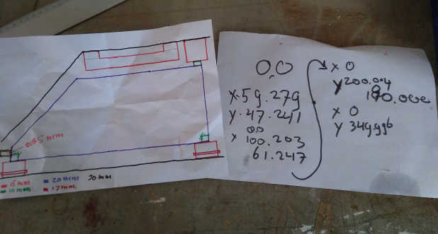
While reversing this new zero point i thought it might be better to do it once, so go straight from the absolute zero to the new position on my wood between the pins. So once i zeroed the final origin, i went manual to the absolute zero, in mind that i then could flip the new coordinate from - to + and i had my new coordinates for the origin of my design and for the future could travel straight from the absolute zero to this spot.
Looked smart, went wrong. One way or another: while zeroing the x-axis, the last push, the machine went over the zero. So the machine lost it absolute zero on the x-axis. I knew w e had this problem before, and it took some time to solve it. And while Emma was not around i contacted Bas. He helped Emma solve this problem a few months ago. Luckily Bas could help me the next morning to fix the absolute zero.
- Menu Value, go to “Input/output switch values”
- look for the “Limits ON or OFF”
- this should be “1- Limits ON”
- “Input switch #2 Mode” should be “2-Nrm Closed Limit”
- Same for “Input switch #3 Mode”
- Menu “(C)uts”
- goto “C3 - Home X,Y Axes using Prox Switches”
No you have reestablished the absolute (or machine) Zero X-Y)
The milling
I started to mill the 2 outsides of the casing first. First the left side of the case.
- In Partworks3D I opened the stl
- Then i went trough all the setting
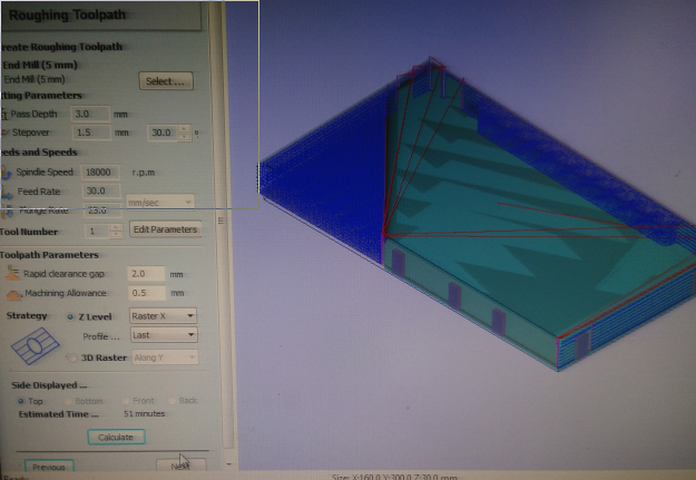
For the roughing and finishing toolpath i choose a 5mm end-mill.
Settings:
| Roughing Toolpath | |
|---|---|
| End Mill | 5mm 2 flute |
| pass dept | 3mm |
| stepover | 1.5mm / 30% |
| spindle | 18000rpm |
| feed | 40.0 |
| plunge | 25.0 |
| rapid clearance gap | 2.0mm |
| machining allowance | 0.5mm |
| strategy Z-level | Raster X |
After the roughing toolpath a loaded the finishing toolpath and started the job. Everything went pretty smooth till now. Also the finishing toolpath went fine. I had some doubts because of the fillets on the side and bottom, but with some sanding afterwards it will look fine.
| Finishing Toolpath | |
|---|---|
| End Mill | 5mm 2 flute |
| stepover | 0.75mm / 15% |
| spindle | 18000rpm |
| feed | 30.0 |
| plunge | 25.0i |
| rapid clearance gap | 2.0mm |
| raster angle | Along X |
I then started, on the same wood, the roughing toolpath for right side of the casing. As before it all went fine and without problems. Just after starting the finishing toolpath (after about 10% done), the bit of the shopbot came loose and cutted a deep straight line through the design. I stopped the machine in time. The bit didn’t came out. So tightening the bit and the job could have been continued. But…
Because of the rough fillets on the previous finishing of the left side i now choose to do the finishing toolpath over the Y-axis, instead of the X-axis. I hoped to get a smoother/nicer result on the fillets.
And now the real problems began. Immediately after i started the job the machine started to do a 30mm deep cut along the Y-axis, making a lot of noise and stuttering. Off course the bit couldn’t do that job. I stopped the machine in time, but there was already coming smoke from the wood and the bit. I noticed the coordinates of the Y-axis were completely out of focus. After checking in partworks3D we saw the deep line in the view mode. I didn’t notice it before… That’s a mistake on my side, that i didn’t check the view modes on all sides. But i think it’s also stupid software (partworks), because it didn’t do stepover on that side. Why not? It was in the setting that i gave into partworks3d?
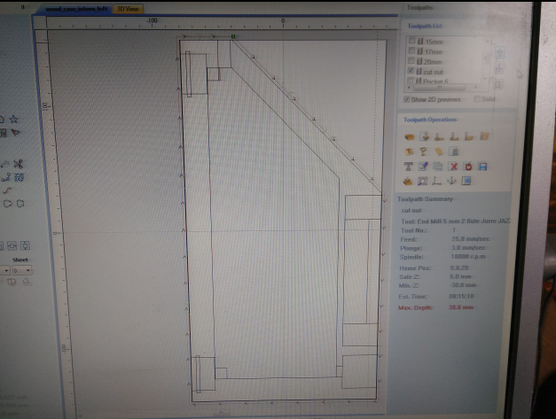
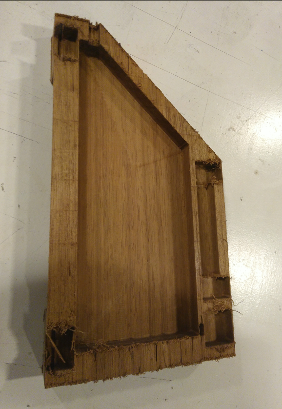
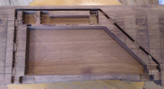
So now i have one left part, the outside with roughing and finishing toolpath done. So i flipped the wood on the groundplate, putting it onto the pins on the Y-axis. I now should do the inside of the wood. I designed this part in inkscape.
While opening the design in Partwork it became clear that there were a lot of open vectors. And i could not close them all in Partworks. So i switched back to inkscape, zoomed in on all corners and edges to close the vectors. Opening the result again in Partworks again gave me lot of open vector. Dammit! And because it are only a few simple pockets i decided to partly redo the design in Partworks. Finally i could flip and mirror the whole 2D design so it became the right pockets in the inside of the left case. I then thought is was clever to do a test run inside the ruined right part of the case, so i could see if the dimensions and the flip of the wood actually came out as planned. So after selecting some squares in the corners of the design and making a toolpath out of them, i started the shopbot. The dimensions and the flip worked as planned!
So i finalized the design / fixing the open vectors in Partworks for the case. Once fixed i started the milling on the shopbot. And soon i noticed that it was wrong. Somewhere in the proces of flipping, mirroring the design, turning the wood, something went wrong so that i milled mirrored!
So this was the 2nd failure. Luckily had 2 reserve piece of wood, already surfaced and with holes for the pins. The next day i will start all over again.
So the next day, i started with the roughing toolpath that went pretty smooth. I then started the finishing toolpath and again the bit cam loose, destroying the case. This time the bit came out and we saw some sparks. So i checked, doubled checked, an checked for another time if there was no fire in the dust collector. To be completely sure i asked another fabacademy student if she could check and double check again.
I had enough this day! And only wood left to do it one more time. So i decided to wait till the next day, before starting a final mill of the in and outside of the case. Without errors, otherwise i’m fucked, and have to do a lot of patchwork to come up with something for the final presentation.
The idea is now to have one side of the case ready, sand it, build all electronics inside, and do the second half of the case after the final presentation.
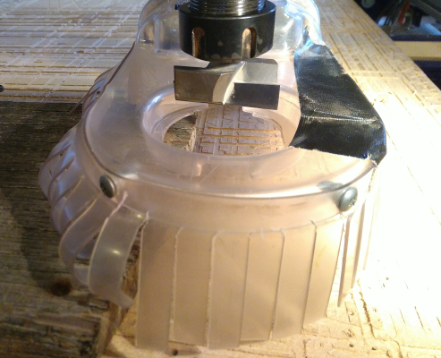
Molding and Casting the piezo holders
I wanted to use silicon as piezo holders. 1. to avoid contact-noise and 2. to get a better, flat position of the piezo and 3. equally flat pressured peizo’s on the ice, to get the best results of the measurements. So i made a form in FreeCad. It will fit in the bottom / feets of the casing of the device, and actually sticks out a little.
I wanted it to contain the piezo and the wires from the piezo. This because i figured out that the wiring of the piezo are very weak. They are soldered roughly to the back surface of the piezo. While testing code with the piezos, ones one wire fall of. So i wanted the piezo one the bottom of the silicon and the wiring through the silicon.
But because lack of time at the end i made it different. There was no time to do a extra step in between. Curing time of the silicon that i used was 16hrs. And i had 36 hrs left for the final presentation. So i made a mold that contains 2 half’s of the block and use glue to stick it together at the end.
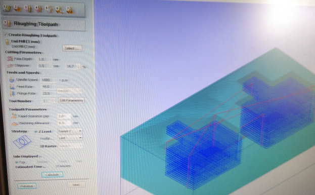
| The settings for Roughing Toolpath in partworks3d | |
|---|---|
| end mill | 3mm |
| pass dept | 1mm |
| stepover | 0.5mm / 16,7% |
| spindle speed | 6000 rpm) |
| feed rate | 40 mm/s |
| plunge rate | 25 mm/s) |
| rapid clearance gap | 2.0 mm |
| machine allowance | 0.5 mm |
| strategy z-level | raster-y |
| settings for Finishing Toolpath (same as above - except-) | |
|---|---|
| feet rate | 30 mm/s |
For the silicon, i used the same Smooth-on PMC 121/30 that i used during the molding and casting week.
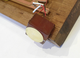
This is the end result. It behalves like i expected: good against contact-noise, leveling and pressuring of the piezos.
I will try to make a whole new casing before Fab14, including the molding and casting i wanted to do initially.
Final words about shopbot
As you may have noticed i spend a lot of time with the shopbot. I really enjoyed working with it. But also got into big troubles and it almost made me change the whole idea for the case of my final project. All in all i’ve spend more than 4 whole days to get…. half a case! Time managment wise it was a disaster. 3 days for the final presentation i had nothing in my hands. I had it all in my head how i wanted to make it, but the “master piece”, the case, wasn’t progressing. Afterwards i’m very happy with the decisions i made, to stay with this concept. If i had changed the wood for softer wood, or even maybe a lasercutted box, the final project would have been “just some electronics in a lasercutted box”.
The problems i faced were from 3 origins:
-
One was the really rough pressure to finalize the project in time. There were days that i woke up at 4 in the morning and immediate started documenting what i did the days before, just because i couldn’t sleep anymore, with documenting, i finally got somethings done.
-
Old machine parts. The collets of the shopbot are probably more than 10 years old. When you push the collet in the nut, it fits, but is very loose. Of course the bits will come out if you give it a nice vibrating job to machine very old hard wood!
-
And then there was me. I wanted it really done. But i also realize that i have a lot to learn. And i did! Specially this week.
Overall i am very glad how all went. I learned a shitload on new skills in so little time! When i show other people this documentation on what i did the last couple of weeks, i always face the fact how much i did and learned.
It was a amazing experience!
After the presentation: 2nd half of the case
As you have seen during the presentation I only had half of the casing ready. So I had to make the second half after the presentation. First i had to finish the documentation. I worked all hours in the 2 weeks before the presentation on the project, carefully taking notes and photos of all steps i made, but there was no time left to do a proper documentation of the whole process and explaining the code, commenting on decisions i made, problems that occurred and solutions and so on. I did that in the days after the presentation. And finally made the 2nd part of the casing.
After nearly a week of fun, frustration and many many problems at the shopbot during the making of the first half, i learned a enormous amount about the machine, how to operate it, what is (im)possible and how to work around problems. The making of the first half worked pretty well and compared to all failures the days before, went on pretty fast. I documented everything so i hoped to do the second half the same way. And it did… more or less. The biggest problem i had this time was something that didn’t pop up the weeks before.
Searching for wood
For making the first half, i spend a lot of wood. No problem, because every time i found some extra wood on the woodpile at home. But now i could not find a single piece that had the right dimensions. And after finding some, they all had old nails. And old wood, old nails: almost impossible to remove. And also hard to find. Finally i found a nice piece that had enough space to make at least the 2nd half, and even had space for 2nd in case of failures. When i prepared it to start the surfacing the top and bottom side of the shelf, i found some strange structure in the middle of the wood, that also turned out to be old nails. Bummer! So at the end i was searching for shelf’s, with nails, that had enough space for one side. I finally found one, that had almost the dimensions i needed. Only on one side the shelf had some decaying… But i hoped to get away with it.
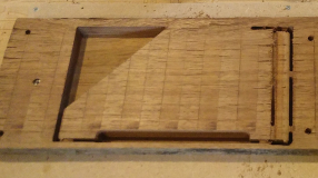
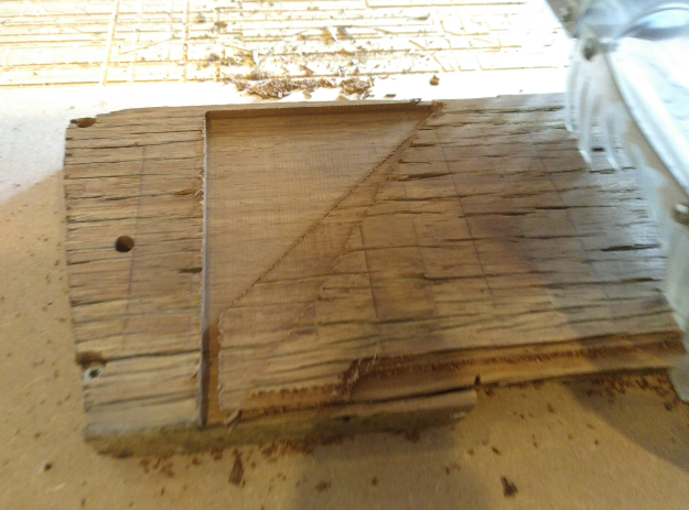
Milling
Luckily i had all my documentation done, so i used it a lot for setting and steps to make. First i did the surface of both sides. That went fast and looked good to me. Only some wood came of unintentionally on the side that had the most problems because of decaying. You see it here in the picture:
With the surfacing of the wood i also made a new artificial layer with the 2 pins for the double sided milling.
After the surfacing i started with outside of the case. Again i did only the roughing path and sanded it afterwards. I could have done the finishing toolpath, but was a bit afraid for the bit coming out and destroying this last piece of wood. And also, maybe as important, the first side was also done this way. So it should have the same process, same finish, and then hopefully the same dimensions! Clever :-) But:
Although i used the same settings as with producing the first part, the shopbot had problems. The X-axis went out of focus. I think it is because the wood is a bit harder, more solid, than the other pile i used before. So i stopped the machine and changed the feed rate (which was 40mm/s) to 30mm/s. I probably also could have speed up the spindle, but because i ran out of spare wood i didn’t want to take any risk. Anyway: i hoped to solve the problem this way and it did!
After flipping the wood the milling of the inside pockets was done without problems. I didn’t change anything on the settings i used before, meaning that i kept the feed rate at 30mm/s.
I checked the dimensions and they are the same as the other part. The damage because of the decaying is not a real problem, It is not interfering the operation of the device and is adding some extras to the old-fashioned appearance.