Final Project
Sleep monitoring
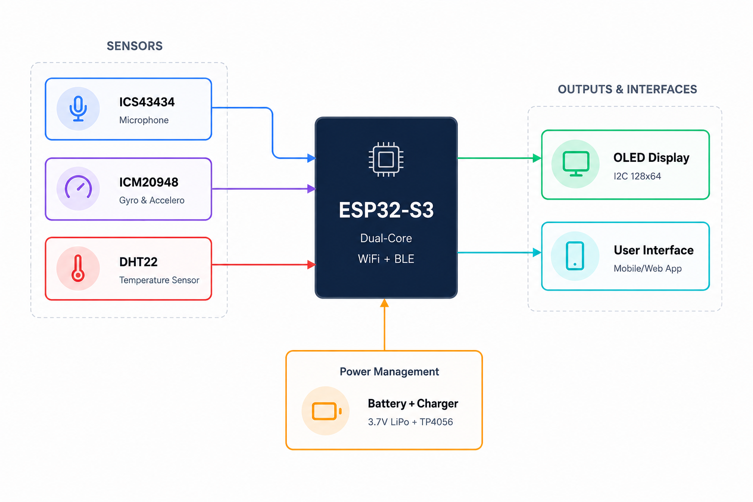
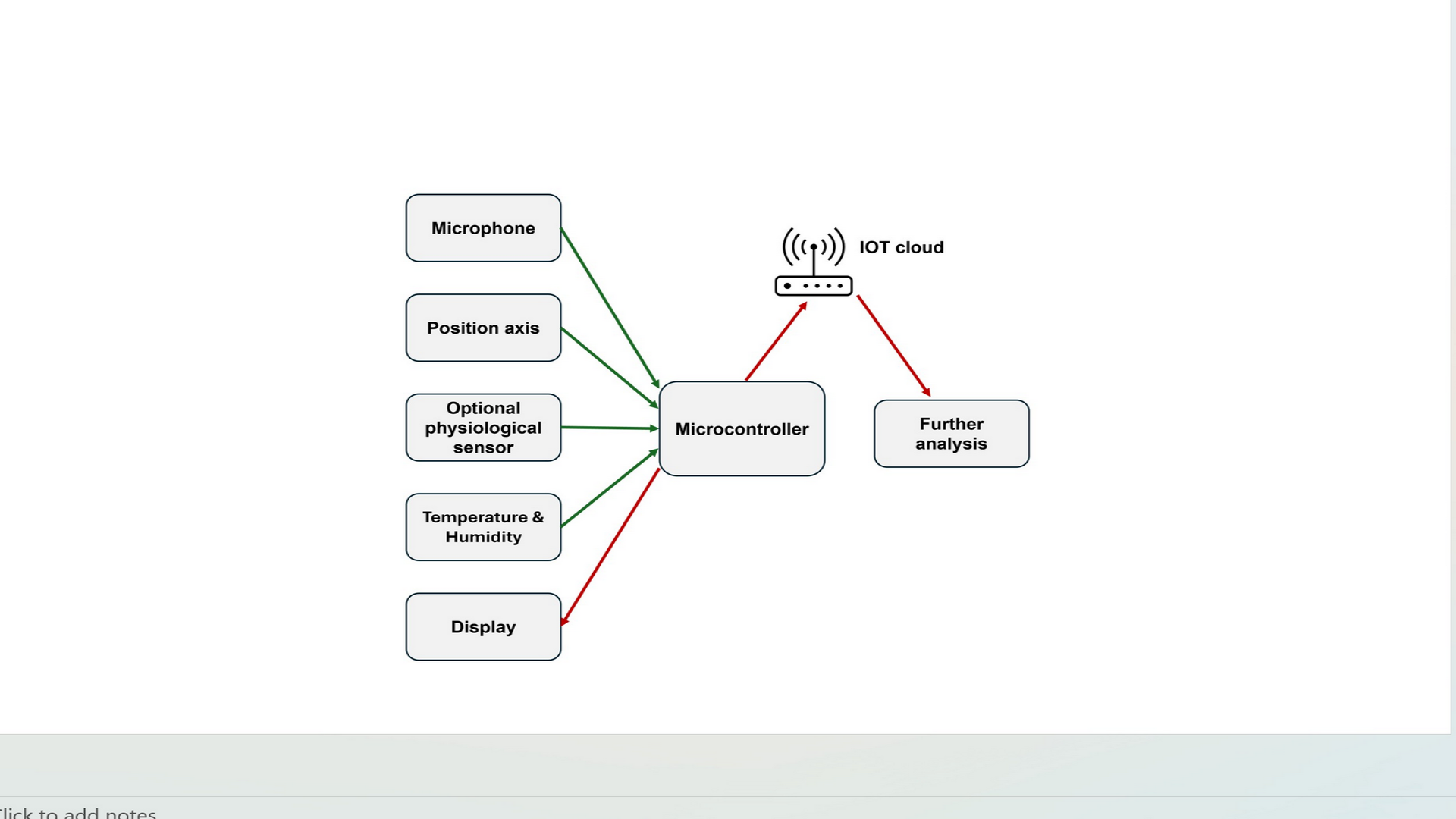
A small, wearable/attachable device that detects snoring on-device and correlates snore events with physical sleep positions, and investigating it with temperature.
List the tasks to be completed
- Drawing a 2D sketch of the device enclosure and its holder
- 3D modeling of enclosure
- 3D printing the enclosure
- Electronic Design
- Electronic production
- Input devices
- Output Device
- Embedded programming for both input and output devices
- Communication and network
- Interface and application programming
1. Drawing a 2D sketch of the device enclosure and its holder
2. 3D modeling of enclosure
3. 3D printing the enclosurees
4. Electronic Design
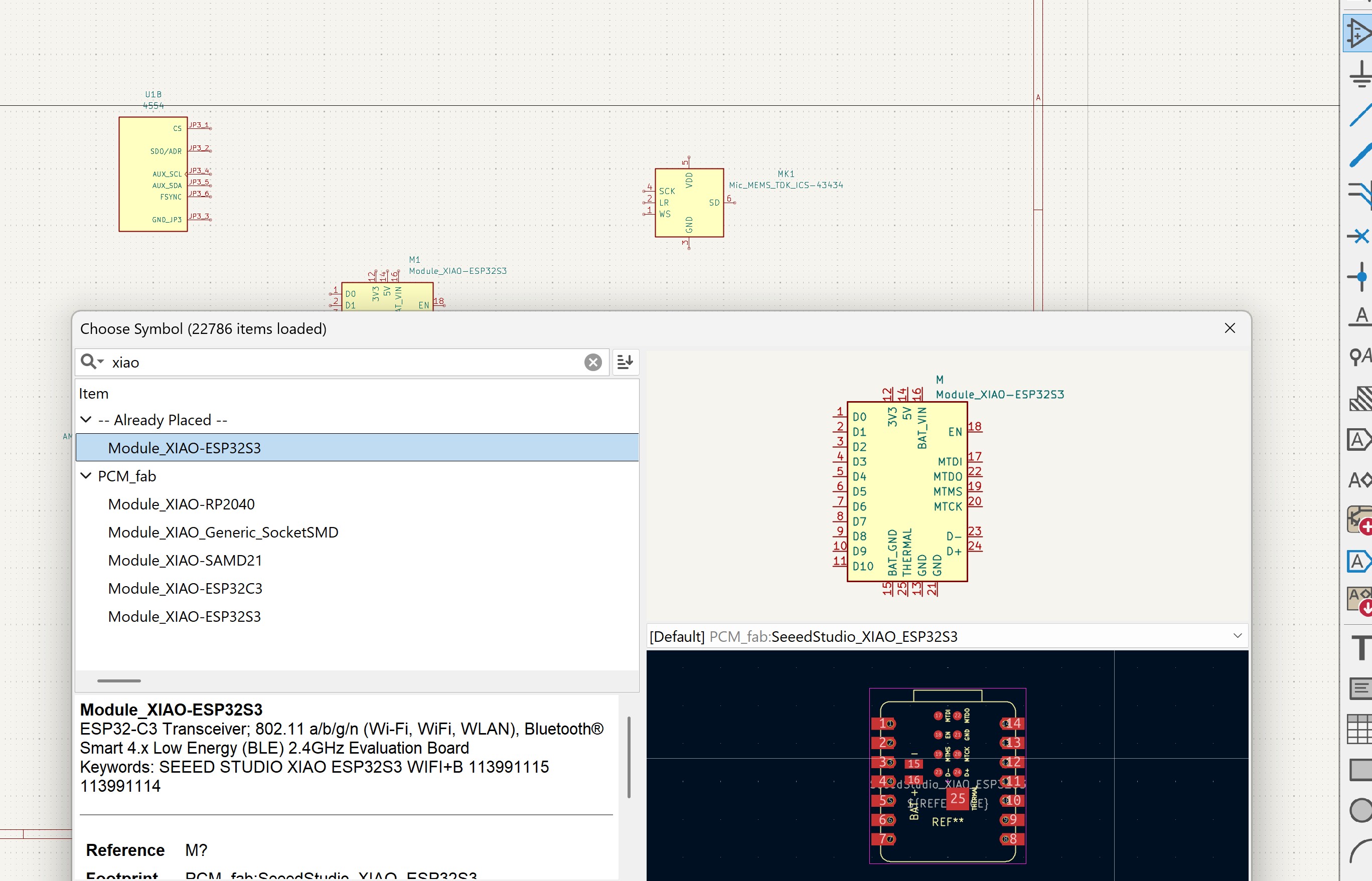
Using KiCad first I designed the Schematic of the board. Starting by adding the components one by one:
The footprint for OLED was not in the KiCad libraries, I followed this webpage, downloaded it and add it to library.
Preferences --> Manage symbol libraries --> add --> navigate to the SSD1306-128x64_OLED.lib file
1. 2D and 3D design of the enclosure
I designed the 2D and 3D in two steps, in week02 and week16.
- In the week02, I explained and documented in details the 2D sketch and 3D modeling of the enclosure.
- And pattern designed in Inkscape, details of explanations is in Wildweek.
3. 3D printing the enclosure
For printing the enclosure I used a Prusa Core L one to print it. I used Prusa slicer to slice the enclosure and set the following setting.
- Organic, low-profile form factor designed in Fusion 360
- Two-part snap-fit shell (body + lid) with press-fit sensor windows
- Internal standoffs for PCB mounting
- A rock for the battery placement
- Material: PLA on FDM printer
4. Computer Controlled cutting
I used both Laser cutter and UV laser cutter for my Final project.
I created a breadboard with Fusion 360 and modified with Inkscape to be prepared for laser cutter. I laser cut it to placed it inside the enclosure and placed all the components.
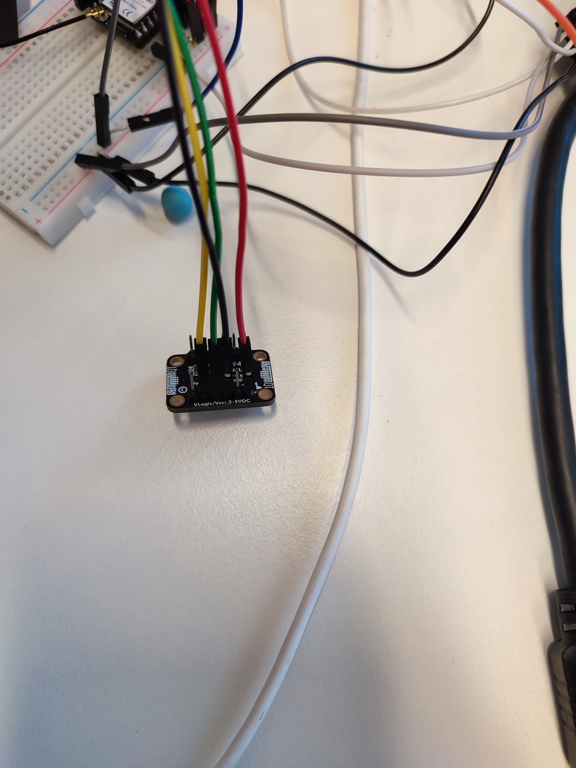
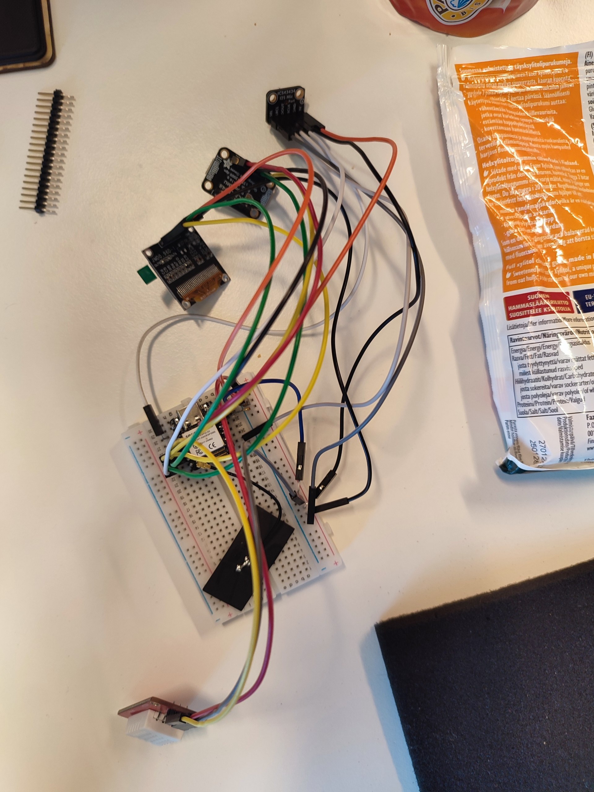
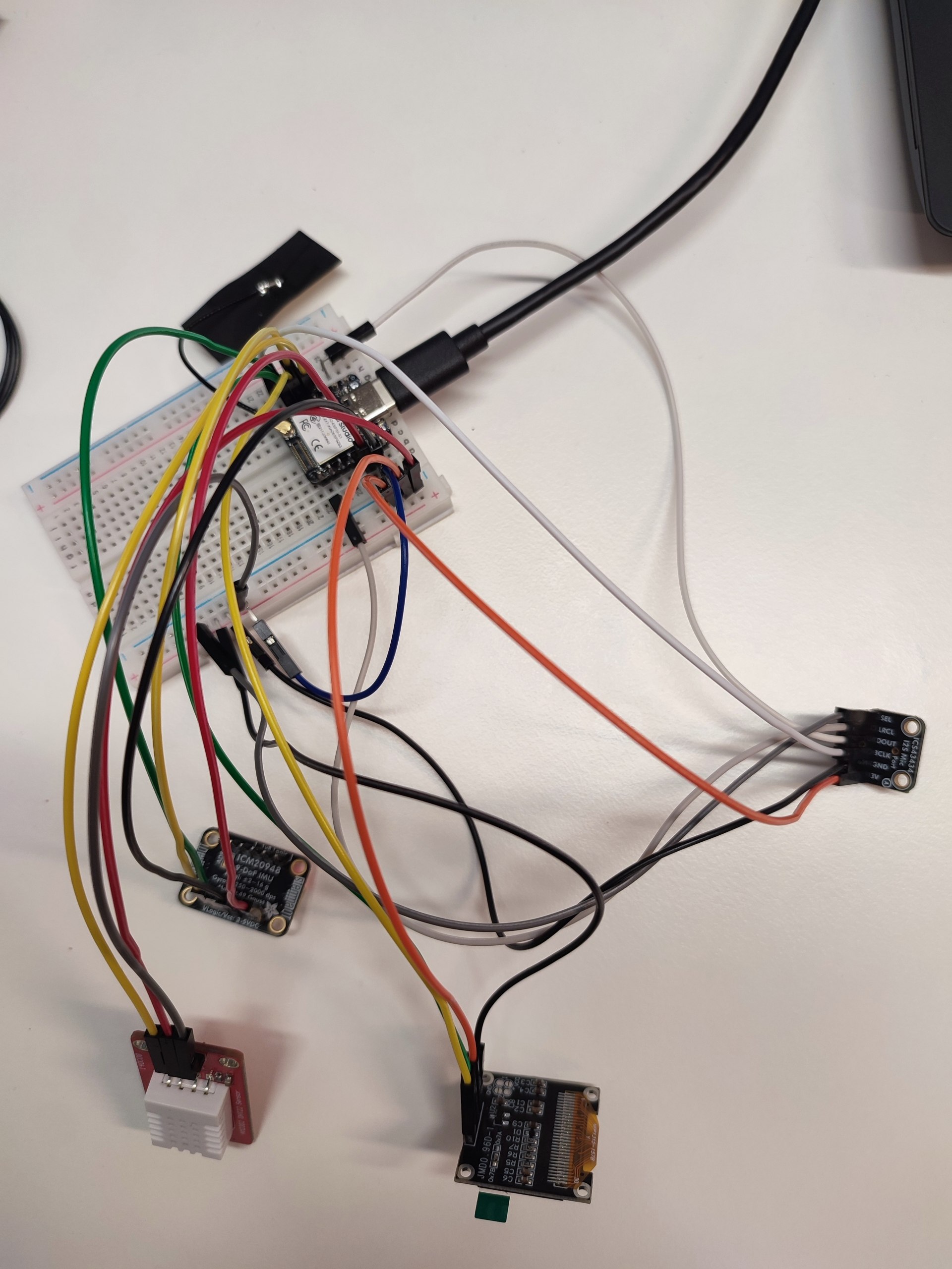
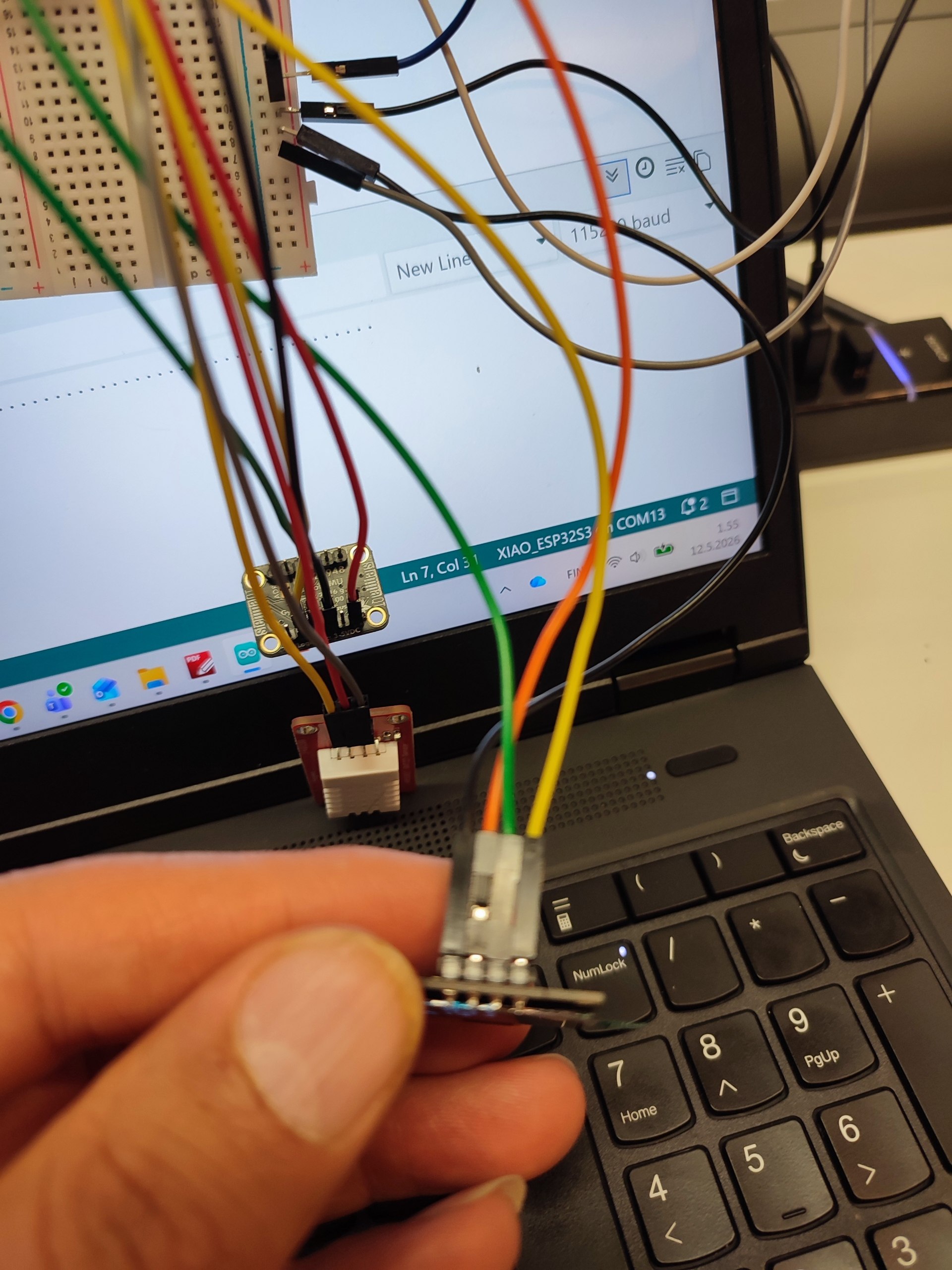
5. Electronic test with breadboard
Before starting doing the electronic design and milling PCB. I started to tested electronic circuit with breadboard.
I will place the breadboard images here with some explanation.
Components
In the System Integration week, I listed main components that use for my final project.
Wiring
For wiring I checked datasheets of all components and XIAO Seeed ESP32-S3.
List of the datasheet:
I also used this website examples.
| Sensor | Signal | GPIO Pin | XIAO Pin | Notes |
|---|---|---|---|---|
| DHT22 | DATA | GPIO4 | D3 | |
| ICM20948 | SDA | GPIO5 | SDA / D4 | |
| ICM20948 | SCL | GPIO6 | SCL / D5 | |
| OLED | SDA | GPIO5 | SDA / D4 | shared |
| OLED | SCL | GPIO6 | SCL / D5 | shared |
| ICS-43434 | BCLK | GPIO43 | TX / D6 | |
| ICS-43434 | WS | GPIO44 | RX / D7 | |
| ICS-43434 | DOUT | GPIO2 | D1 | |
| ICS-43434 | L/R | GND | GND | |
| all GND | GND | GND | ||
| all VCC | VCC | VCC |

5.4 Test
6. Electronic production
7. Input devices
8. Output Device
9. Embedded programming for both input and output devices
11. Communication and network
11. Interface and application programming
12. System integration
Summary of Fabrication Processes Used
| Fab Academy Unit | Application in This Project |
|---|---|
| Computer-Aided Design (Week 2) | Fusion 360 enclosure, |
| Computer-Controlled Cutting (Week 3) | Laser-cutter |
| 3D Scanning & Printing (Week 5) | FDM printed enclosure |
| Electronics Design (Week 6) | KiCad schematic and PCB layout |
| Electronics Production (Week 8) | PCB milling, soldering, testing |
| Input Devices (Week 9) | I2S mic, IMU, DHT22 |
| Output Devices (Week 10) | OLED display, BLE/Wi-Fi data output |
| Networking & Communications (Week 11) | BLE notifications + Wi-Fi HTTP server for dashboard |
| Interface & Application Programming (Week 15) | Web dashboard, data visualisation |
| System Integration (Week 16) | All subsystems integrated into a single enclosure |
In System integration week, I explained and showed my final project as a sample of system integration. I explained how the components placed and connect together.
Final Presentation
Slides
Download slide: presentation.png
Video Presentation
Watch the final presentation video:
▶ Presentation Video (MP4)