Week 16 | Wildcard week
Overview
This week’s assignment was to explore a new digital fabrication process not covered in previous assignments. I chose laser cutting and UV printing to print logo's on the lid of enclosure for my final project enclosure.
UV lasers operate at a short wavelength (typically 355 nm) and use cold ablation rather than thermal processing. This results in minimal heat-affected zones, higher precision, and cleaner edges, making the process especially suitable for fine details.
This process is part of my final project by enabling the creation of lid with precise features, logos, and text.
Assignment Requirements
- Design and produce something using a digital process (CAD + CAM) not covered in other weeks.
- Document the workflow so others can reproduce it.
- Include characterization, settings, challenges, and results.
3. Design Process
Software used: Fusion 360 & Inkscape for 3D and 2D design.
I explained here how I designed the enclosure and its lid during earlier weeks. For this wildcard week, I reused the 3D model of the lid that I had previously created in Fusion 360 and did some modification for UV laser printing.
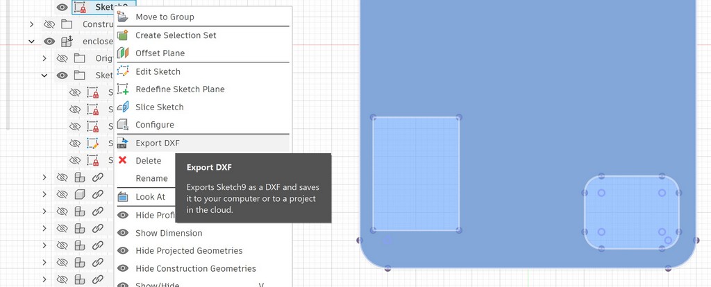
The main modifications were done in Inkscape. I exported the top face of the lid as a DXF file from Fusion 360, imported it into Inkscape.
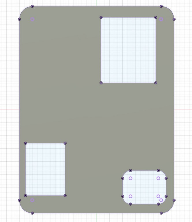
I exported the DXF file from Fusion 360.
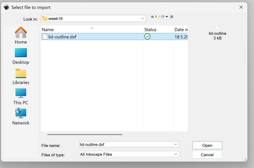
Imported to Inkscape:
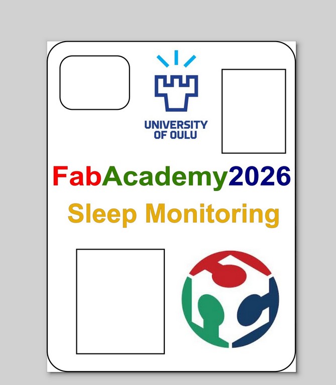
To personalize the lid and match the Fab Academy documentation style, I imported the official FabAcademy and Oulu University logos. I carefully scaled and positioned them to achieve a clean and balanced layout.
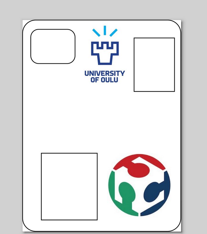
I also added descriptive text to the model, including the project title. All text was converted to paths to avoid font compatibility issues during UV printing.
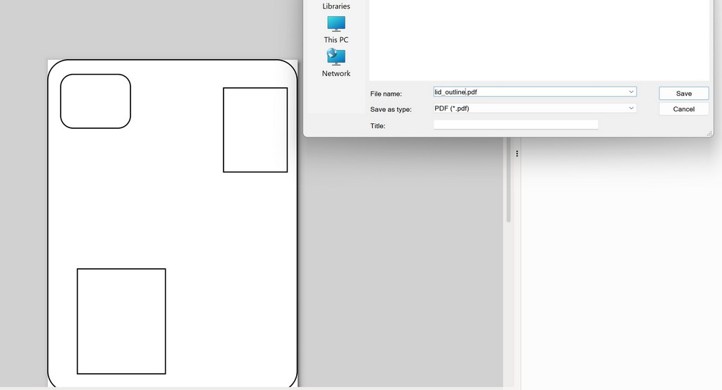
For efficient fabrication, I exported the design into two separate files:
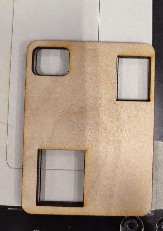
- One file containing only the outline/profile (for cutting). The idea is to first have the exact profile in printer, then I inserted the lid in the exact profile ta having fit allignment.
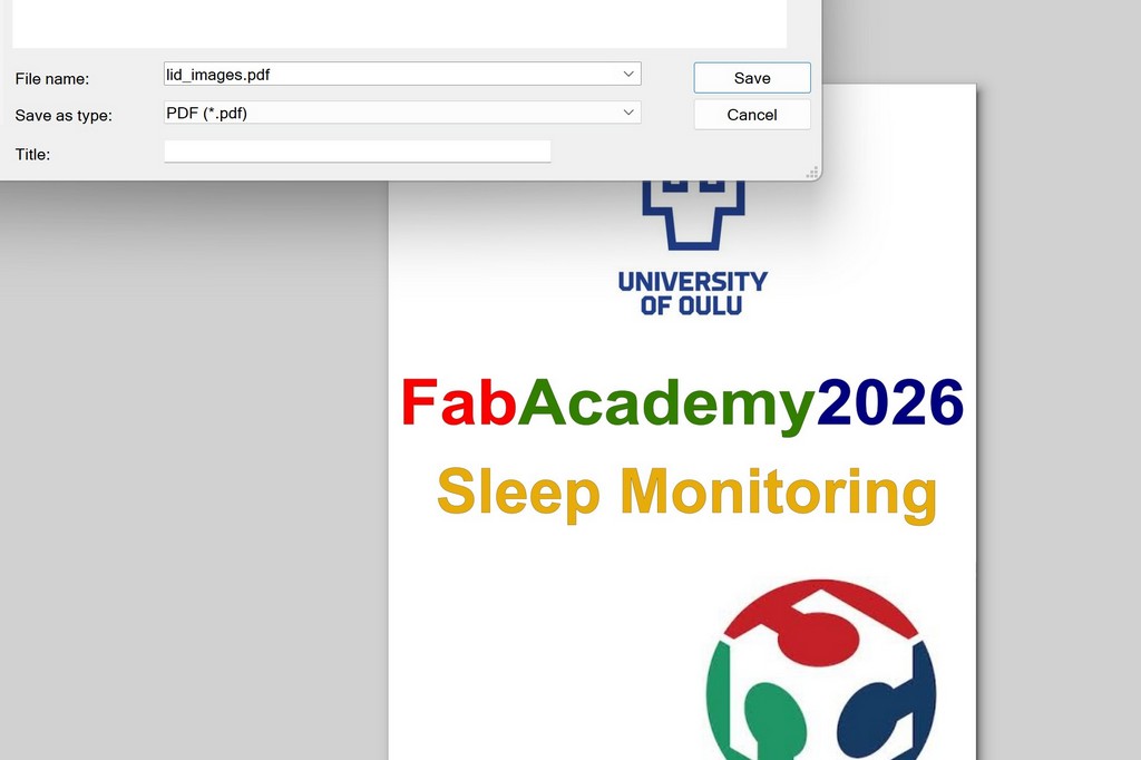
- Another file containing the graphics, logos, and text (for engraving/printing).
This split workflow allowed me to first print the lid profile from the stock material and then precisely align the lid back into the cutout for engraving the surface details without misalignment.
4. Printing Process
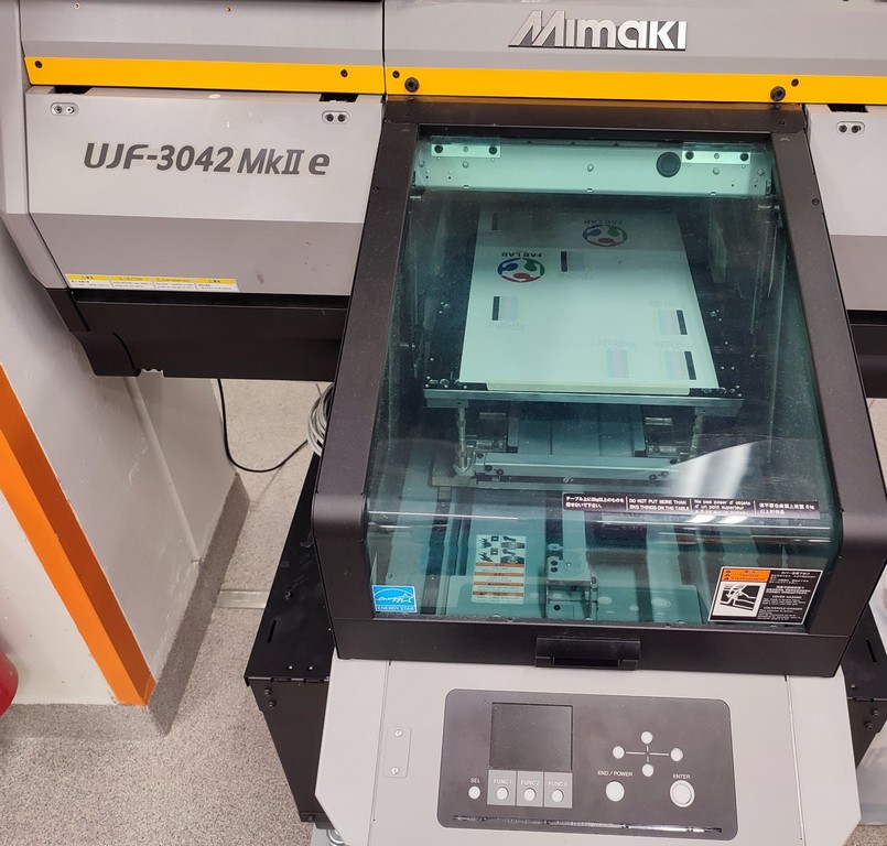
The UV laser cutter available at Oulu Super Fab Lab is the Mimaki UJF-3042MkII e. It is the successor to the UJF-3042MkII and functions primarily as a flatbed UV inkjet printer while also supporting high precision UV processing. The machine supports A3-sized workpieces with a maximum height of 153 mm.
The Mimaki UJF-3042MkII e UV flatbed inkjet printer was used for direct printing on the lid for enclosure. This UV printing machine jets UV-curable inks that are instantly cured by UV LEDs, allowing high precision, excellent detail reproduction, and vibrant colors with minimal processing time. The machine supports A3-sized workpieces with a maximum height of 153 mm.
Key specifications of machine can be find here.
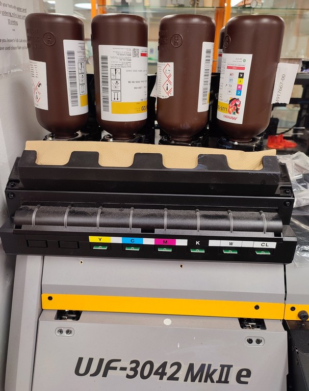
The ink bottles are located at the left front of the machine for easy access and monitoring of ink levels.
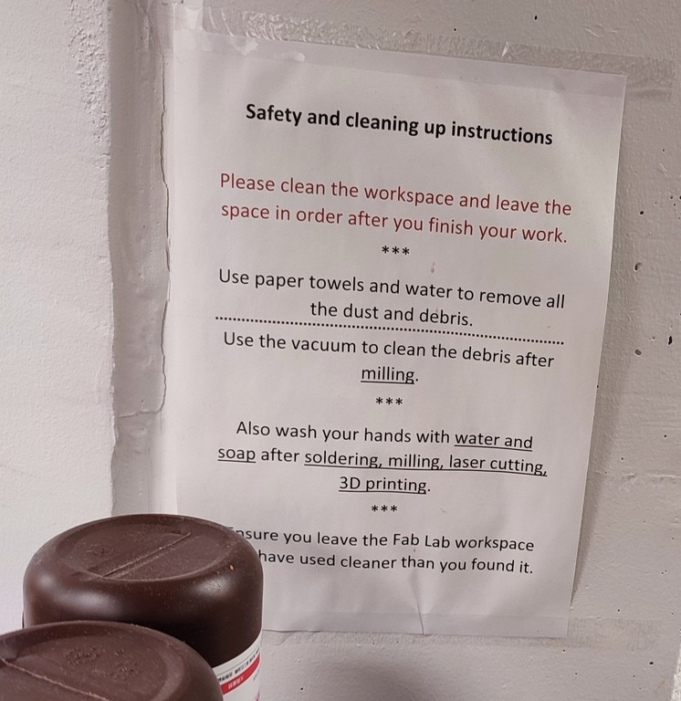
The machine features a dedicated safety and cleaning structure, including proper ventilation, emergency stops. I learned from Fab Academy course before start using any machine, I reviewed the safety instructions before starting any operation.
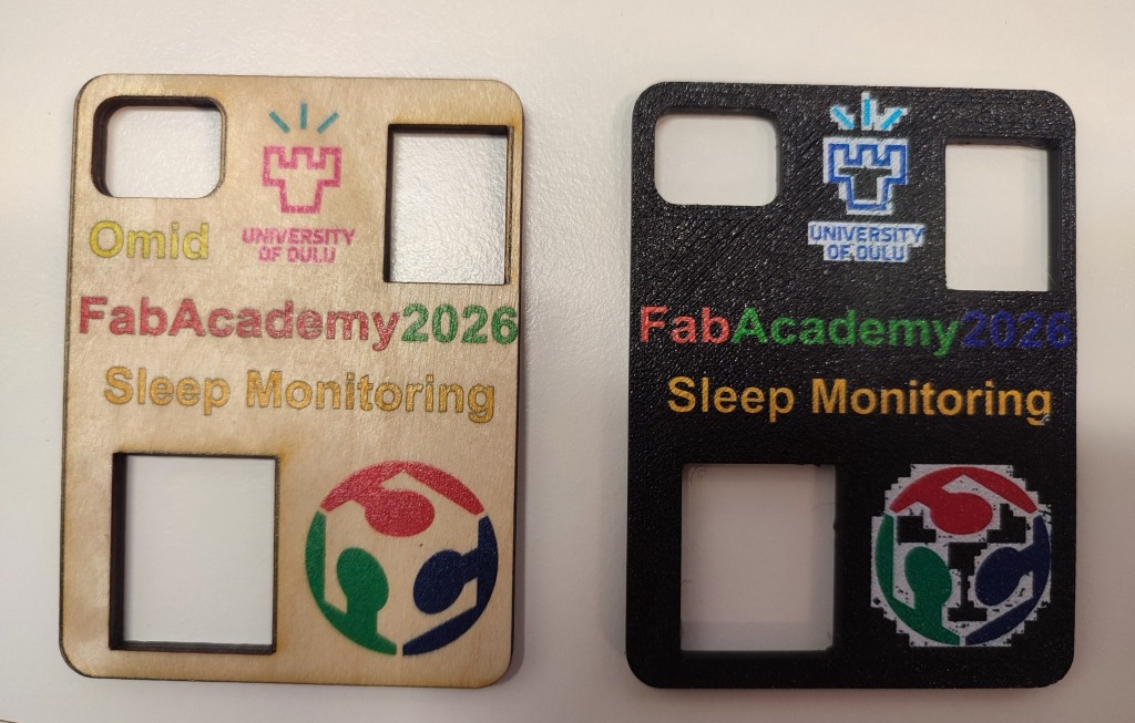
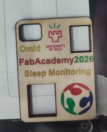
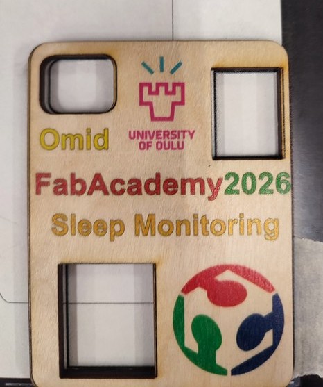
In the first tried of using this printer, Anti helped me and I was able to print but there was a problem with my model that my print was not high resolution. In the following images it can be seen that both FabAcademy and Oulu University Logos did not have high resolution:
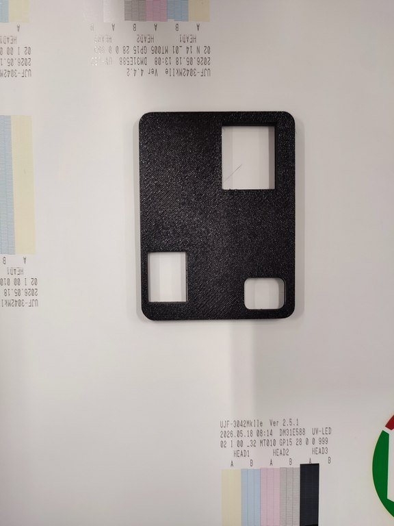
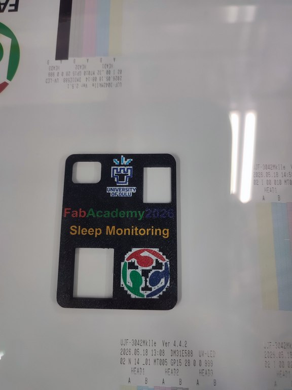
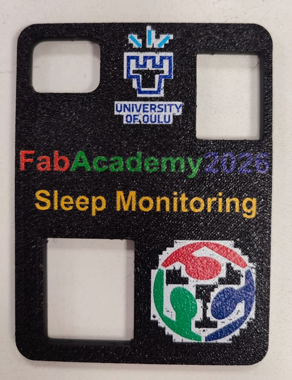
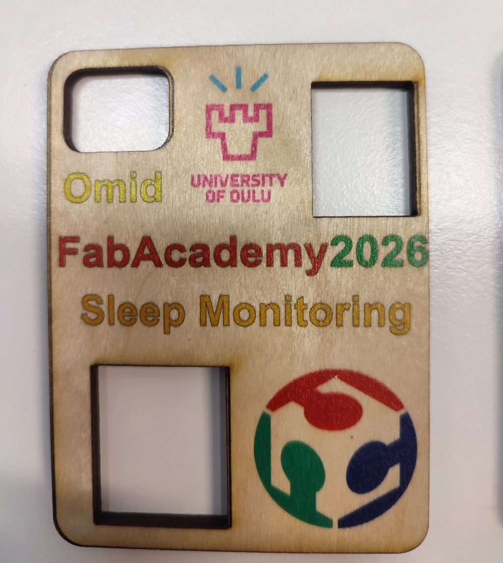
The reason was that in the Logos there were a background colors. I went back and downloaded the Fabacademy svg file and for Oulu University from its Material bank downloaded the original Logo and import it in my model and as it will be shown later here the printed logos have very high quality.
In the following I explained in details the instruction of using this machine as this is the first time I am using this machine, for later my and other use.
Printing with printer
The software for using Uv printer is Mimaki Rasterlink7.
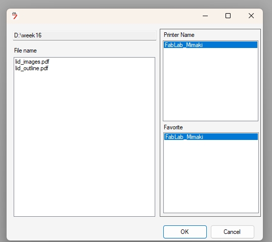
Similar to most all the software first I imported the models into the software. I had two model to make it easy to print: a outline to positioned the lid exactly in the exact position and the images that I had plan to print on the lid.
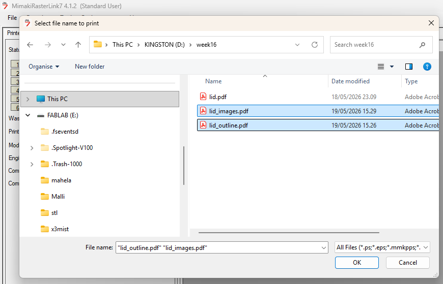
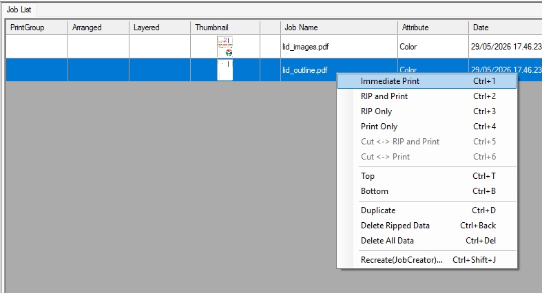
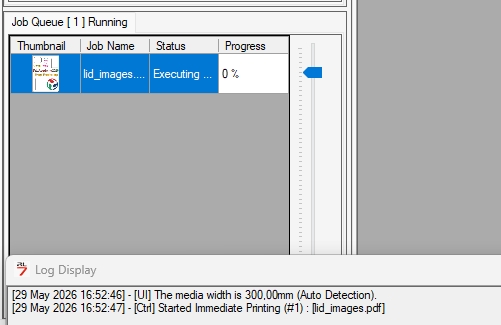
First I started with outline. Right click on it and chose Immediate print:
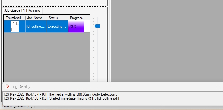
There was Job Queue Running in the left sidebar showing percentage uploading file into the printer. I waited to it done to 100 %.
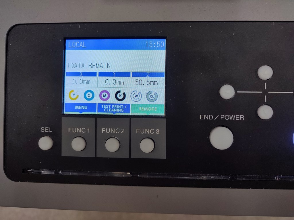
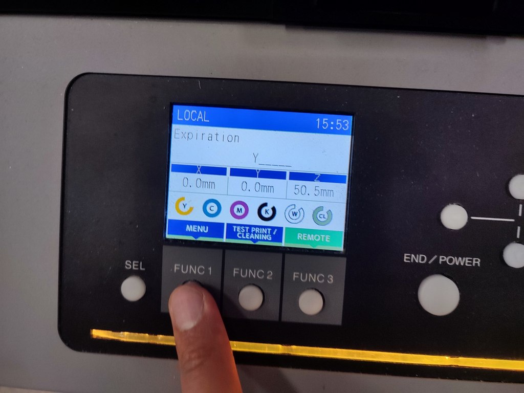
There were a few step to be done on the printer panel. On the panel after saw the DATA REMAIN message:
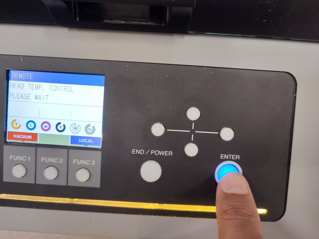
Pressed the ENter and then press REMOTE:
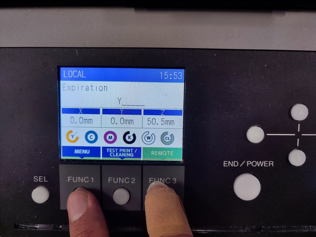
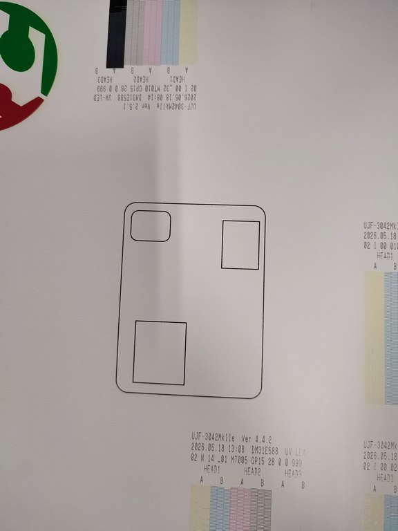
The outline printed:
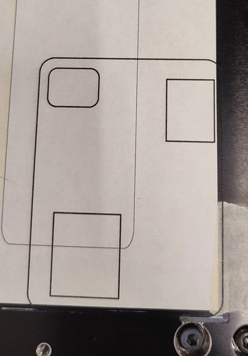
I placed the Lid inside the outline which I cut it with laser cutter. I tried my best to be precise.
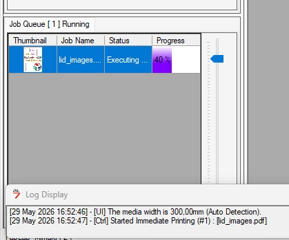
Then I send the images file to print.
Right click and click on Immediate print.

I waited again for Job Queue Running to be 100 percent:
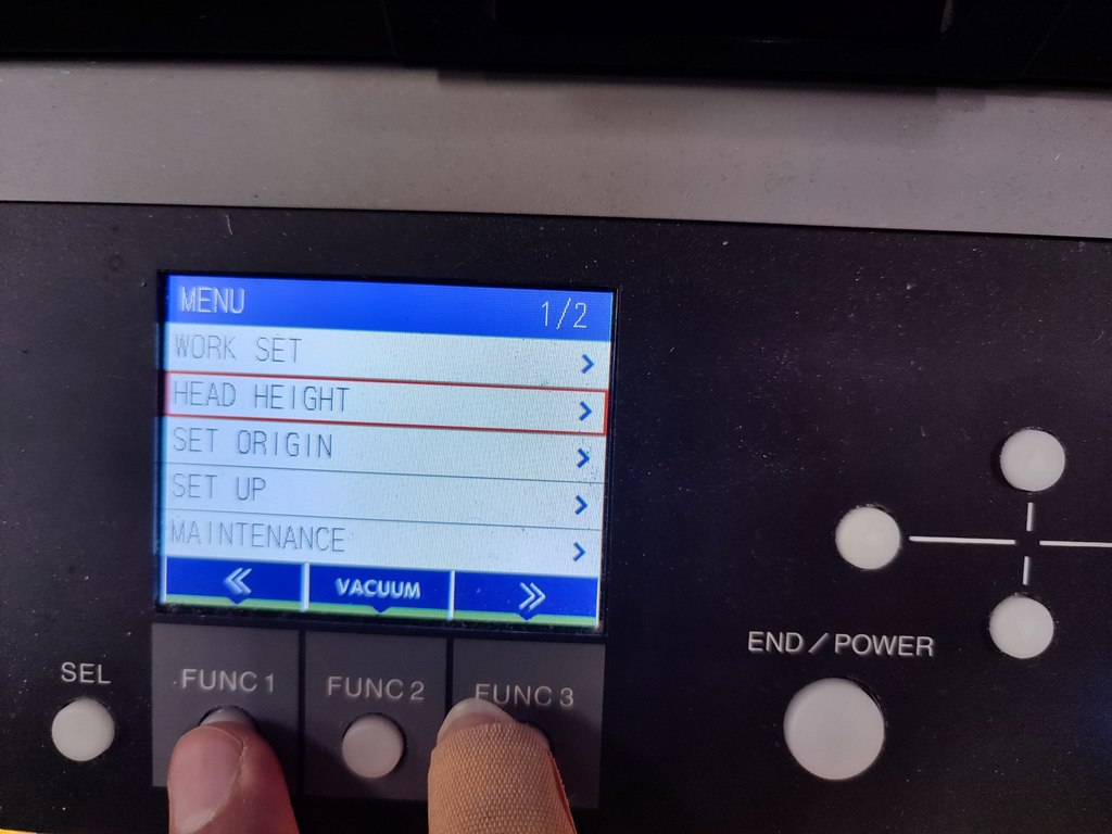
For this step, in the panel a few step needs to be ste: in the menu:
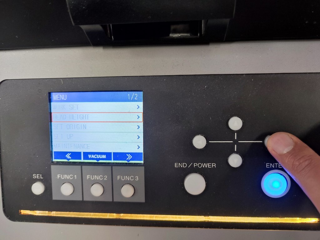
Selected HEAD HEIGHT:
Went to next menu with right key:
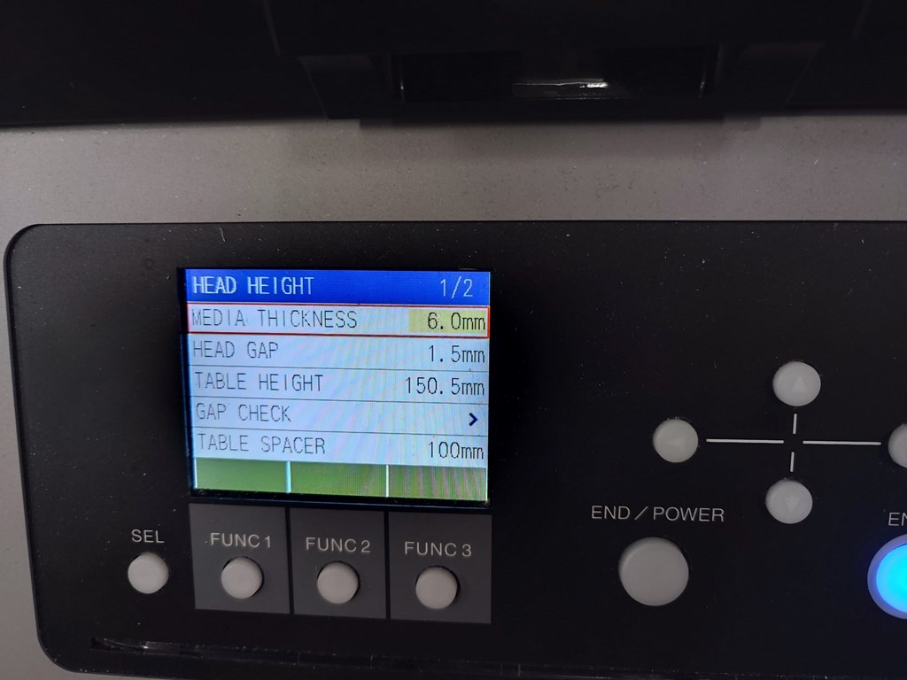
The height of the lid was 4 mm, so, I set the MEDIA THICKNESS to 5 mm which is based on the height of the lid. Typically, the MEDIA THICKNESS has to be set based on object's height plus 1-mm. Antti, confirm this.
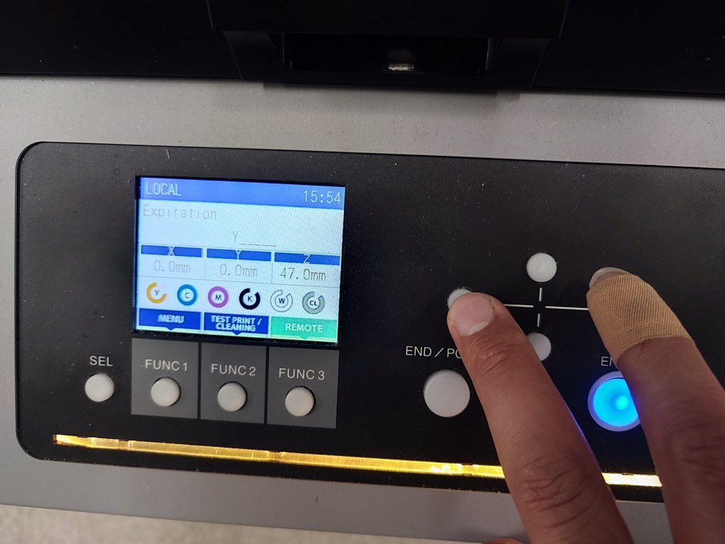
Pressed twice the left side key to back to the menu and press the remote to start printing.
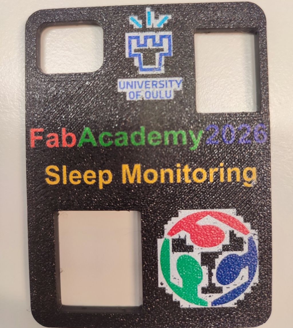
The differences between the printed can be seen clearly here: