Week 15 | System integration
Overview
Design and document the system integration for your final project
Assignment
This week my tasks were as following:
- made a plan for system integration for your final project?
- documented your plan with CAD and/or sketches for system integration?
- implemented methods of packaging?
- designed your final project to look like a finished product?
- documented system integration of your final project?
- linked to your system integration documentation from your final project page?
Final project block diagram
Here is the block diagram of my final project- Sleep monitoring, including ESP32-S3, temperature and humidity sensor, MEMS microphone, Ghyroscop and accelerometer, a battery and its USB charger, and UI in the mobile app:
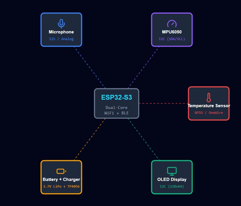
Final Project main components
By today the main components which I will use in my final project are as follow:
- Microcontroller: XIAO ESP32-S3
- MEMS Microphone: ISC-43434
- Gyroscope + Accelerometer: ICM20948
- Temperature & Humidity Sensor: DHT22
- OLED Display
- LiPo Battery
- 3D Printed Enclosure
- A lid for enclosure either with laser cutter or 3D printed
2D and 3D Model of Final Project
One of the biggest advantages of my final project for sleep monitoring is its portability. It is an enclosure that should be as small and light as possible so the device becomes easy to carry everywhere and comfortable to use every night. Because this device is designed to help people track their sleep, it needs to fit naturally into their daily routine. A big or heavy device would be annoying to move around, especially when traveling, staying at a friend’s house, or simply moving between rooms. That’s why I decided to make the enclosure compact and lightweight from the beginning.
In order to achieve good portability, I focused on reducing the overall size while still keeping enough space for all the important parts like the battery, PCB, sensors, and OLED display. I started with a larger box and then adjusted the dimensions after placing the real components. This process helped me understand the minimum size I could reach without making assembly difficult or limiting the electronics. The final design feels much more practical and user-friendly.
Making the enclosure small and light also improves the user experience. People are more likely to use the sleep monitor regularly if they don’t have to worry about its size or weight. Whether they are students, travelers, or just someone who wants better sleep, a portable device encourages consistent use and gives more freedom. This was one of my main goals while designing the 3D model.
So, based on the above explanations, the enclosure will have two main parts:
- The bottom part holds the battery and its charger.
- The top part is for the main PCB, sensors, and OLED display.
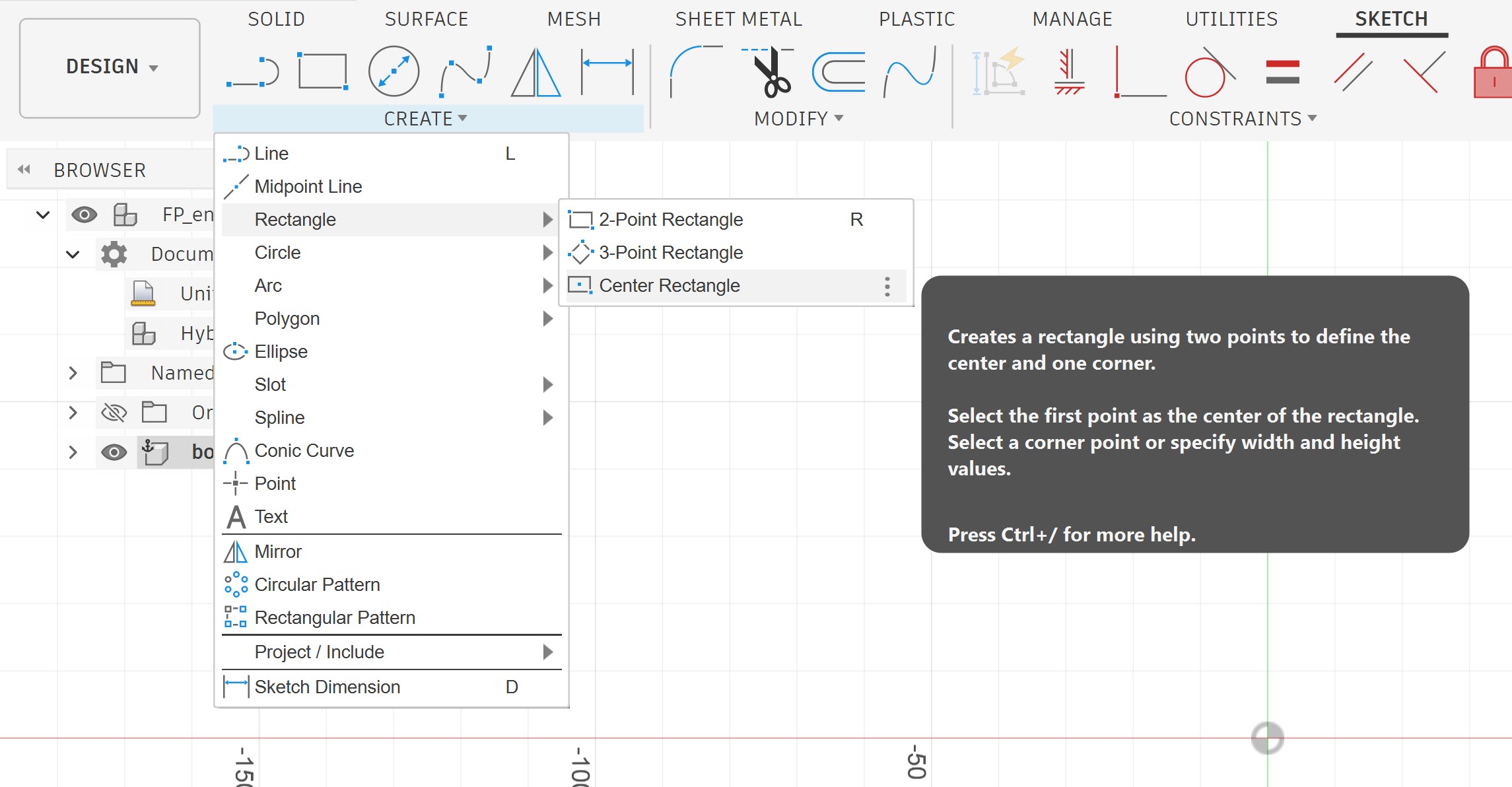
I started with a simple sketch, a rectangle:
The size of the box I assumed was 100 mm by 80 mm.
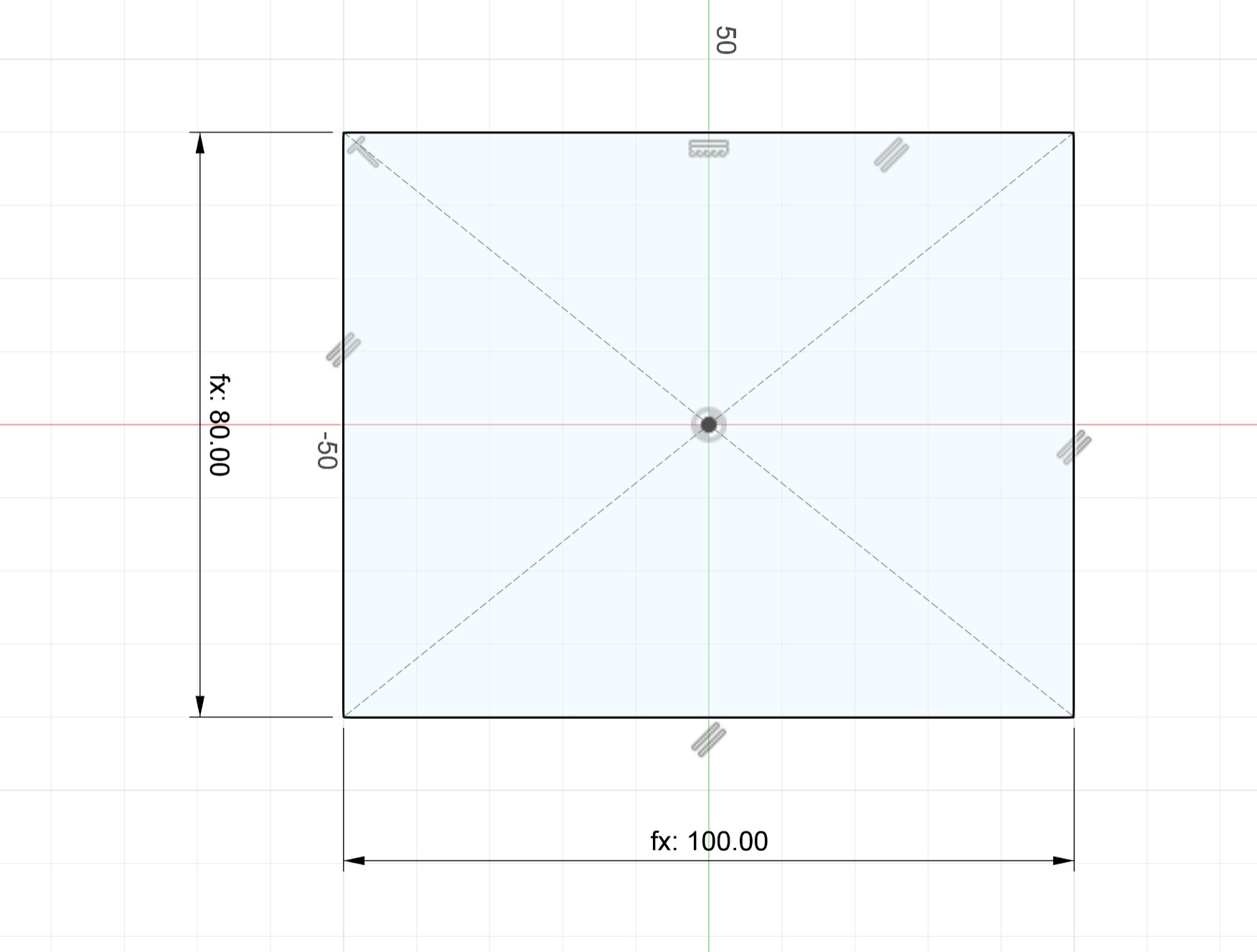
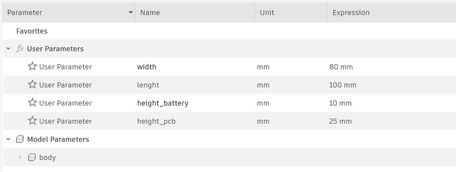
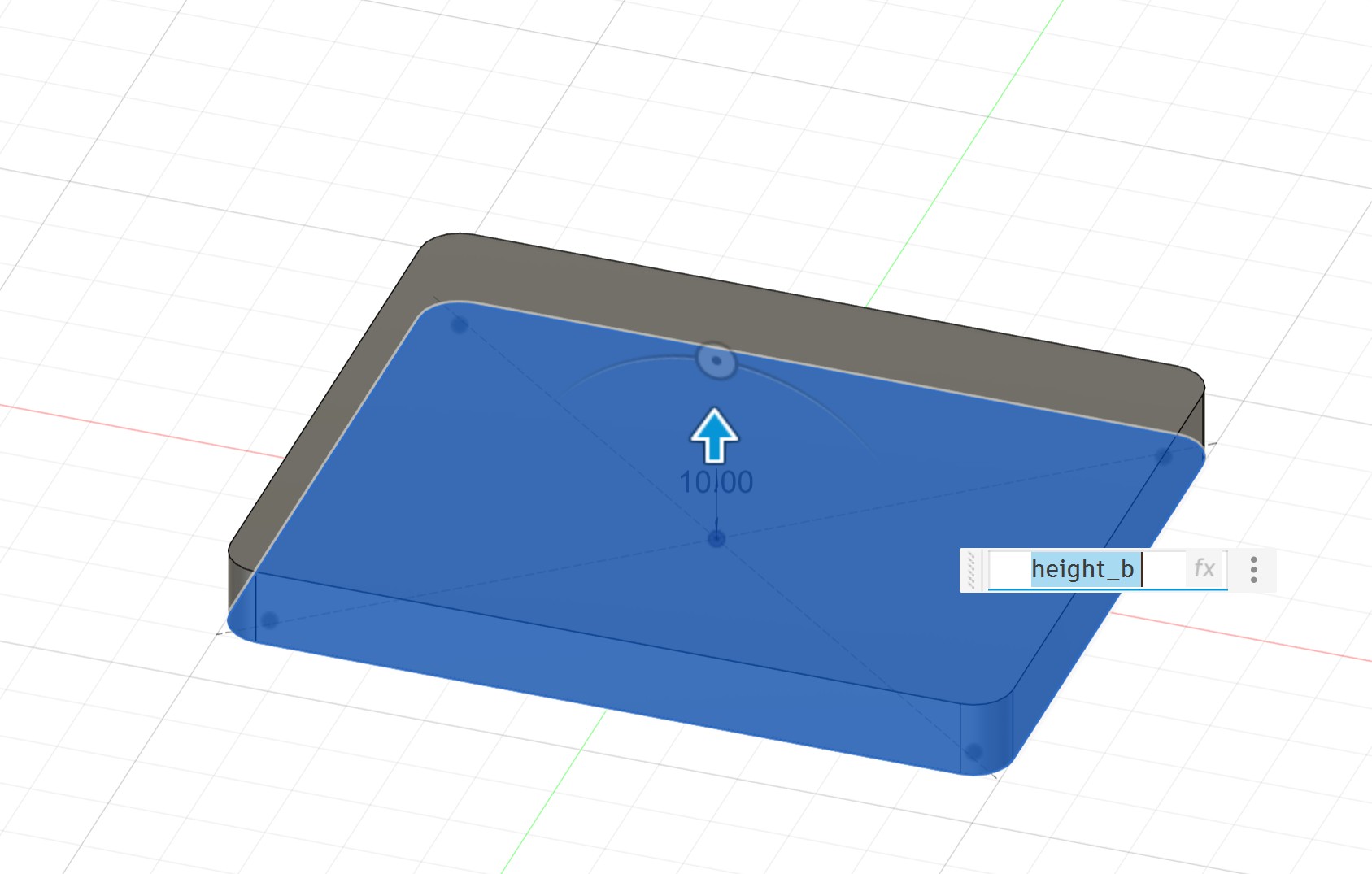
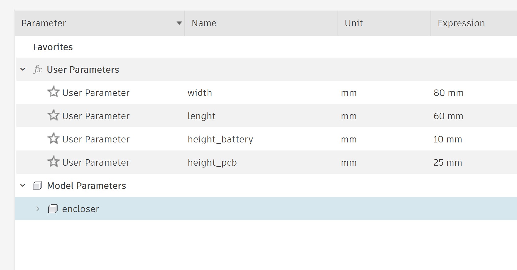
I defined some parameters so I can easily modify the box later to fit my exact needs.
I extruded it:
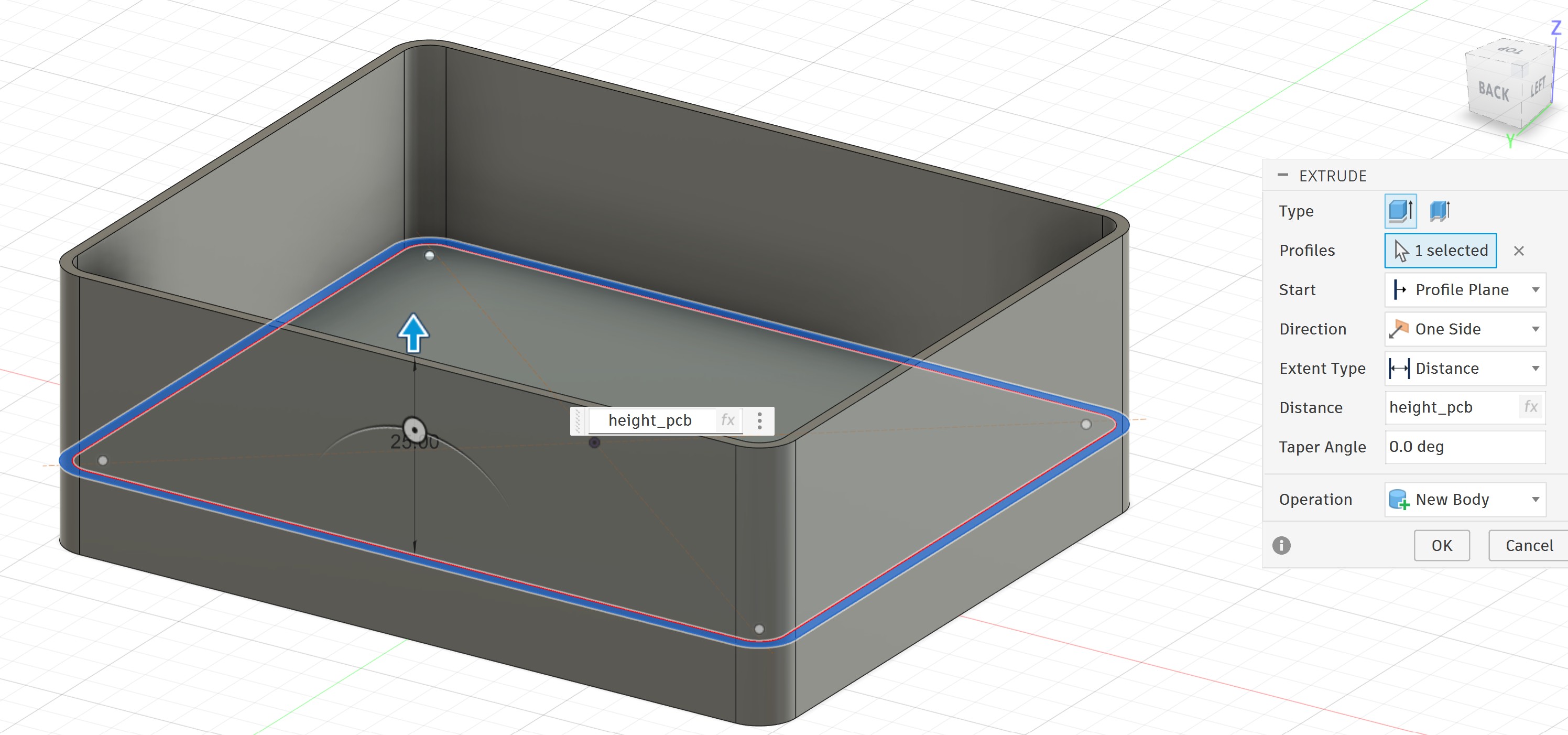
I drew a new sketch for the PCB. Here I used the same size as the battery area for now. I will change it later.
I extruded it:
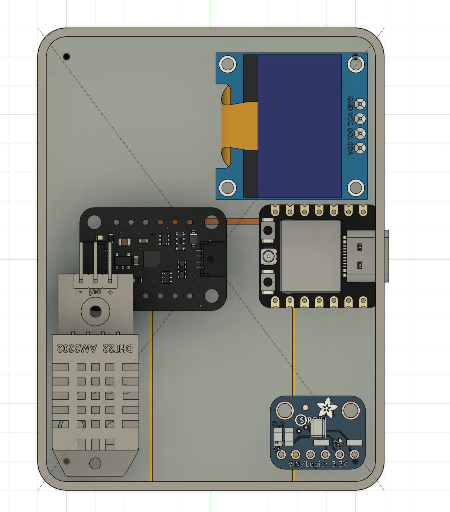
I got the step files of the components from Grabcad, and I uploaded them one by one and inserted them into the model:
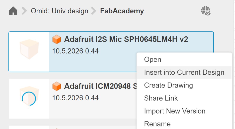
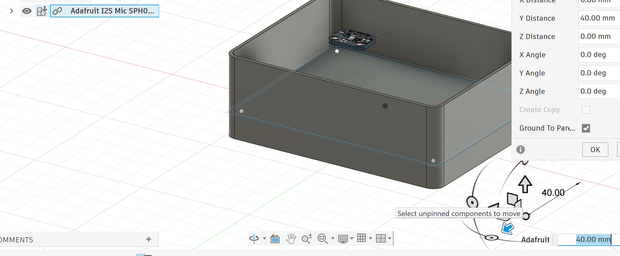
I imported all the components successfully:
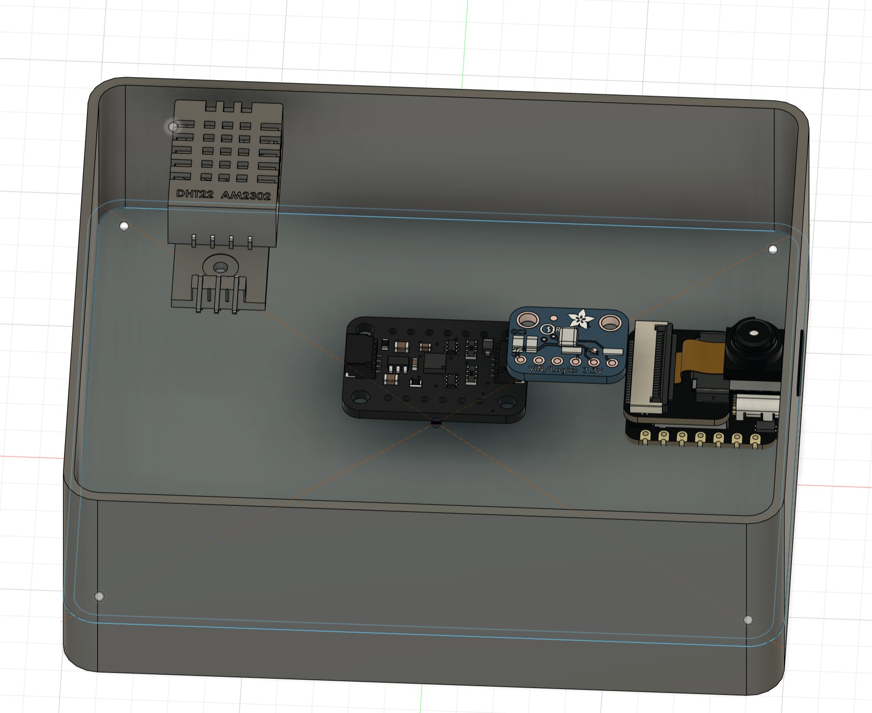
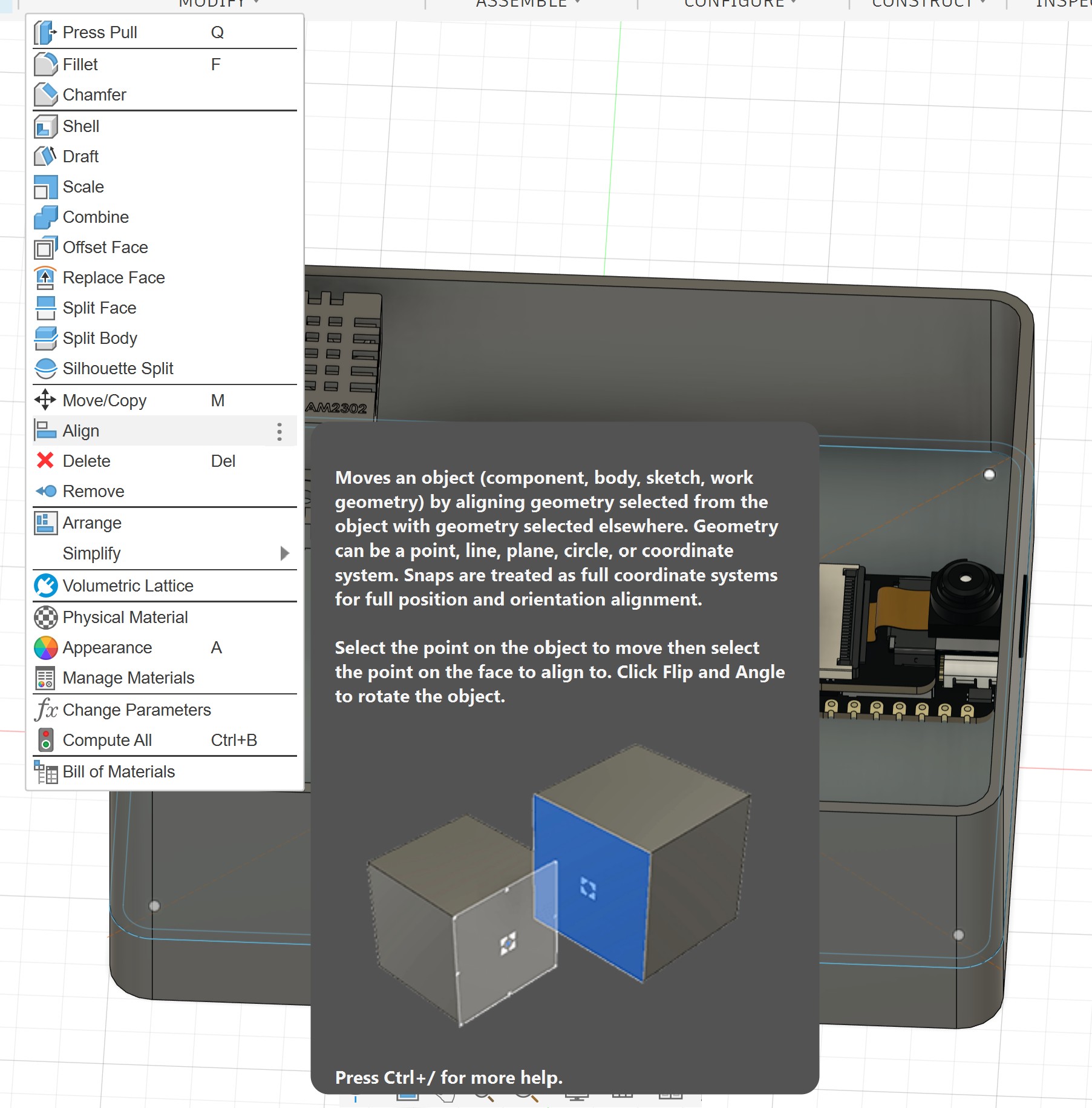
I aligned them:
After aligning and placing all the components, I found that the enclosure was bigger than I expected. So I went back to the parameters and adjusted it.
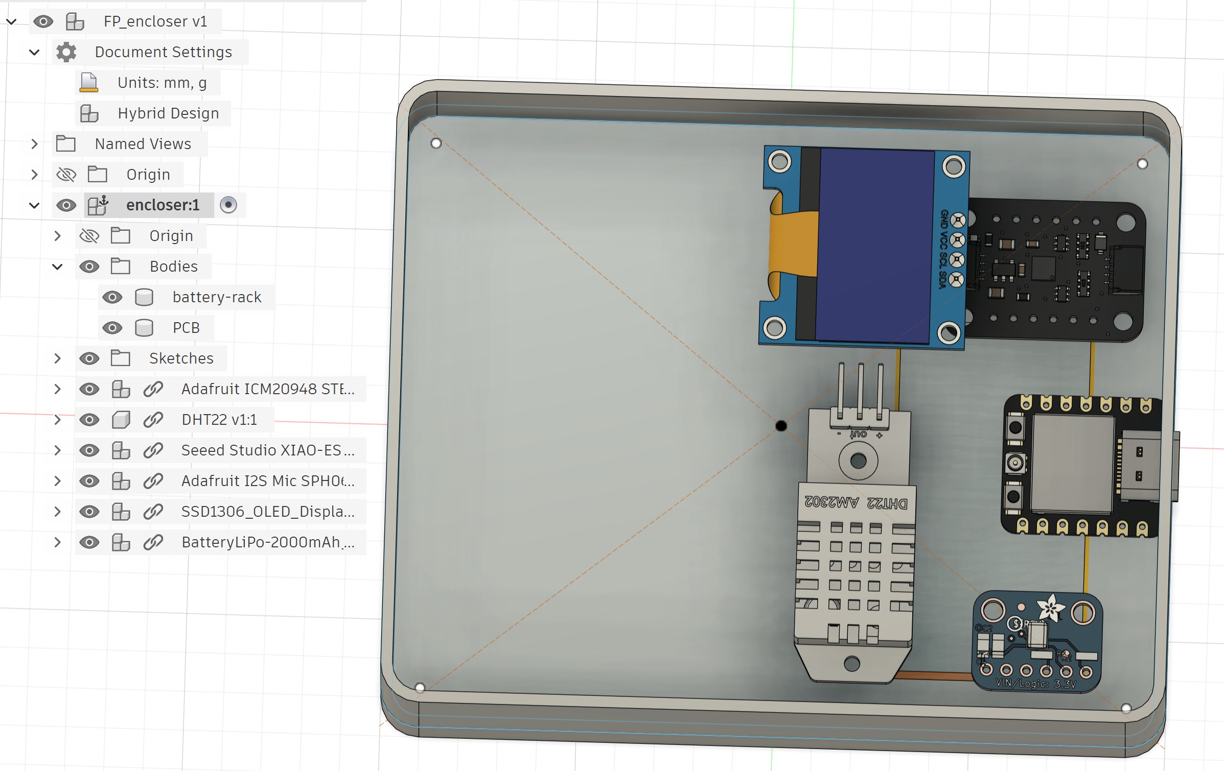
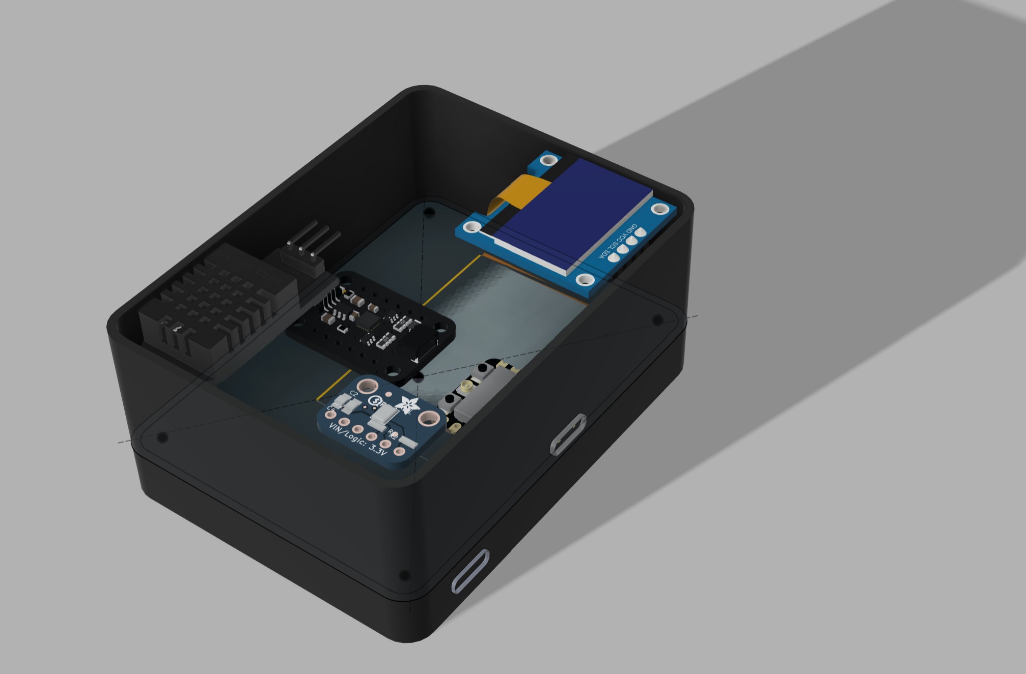
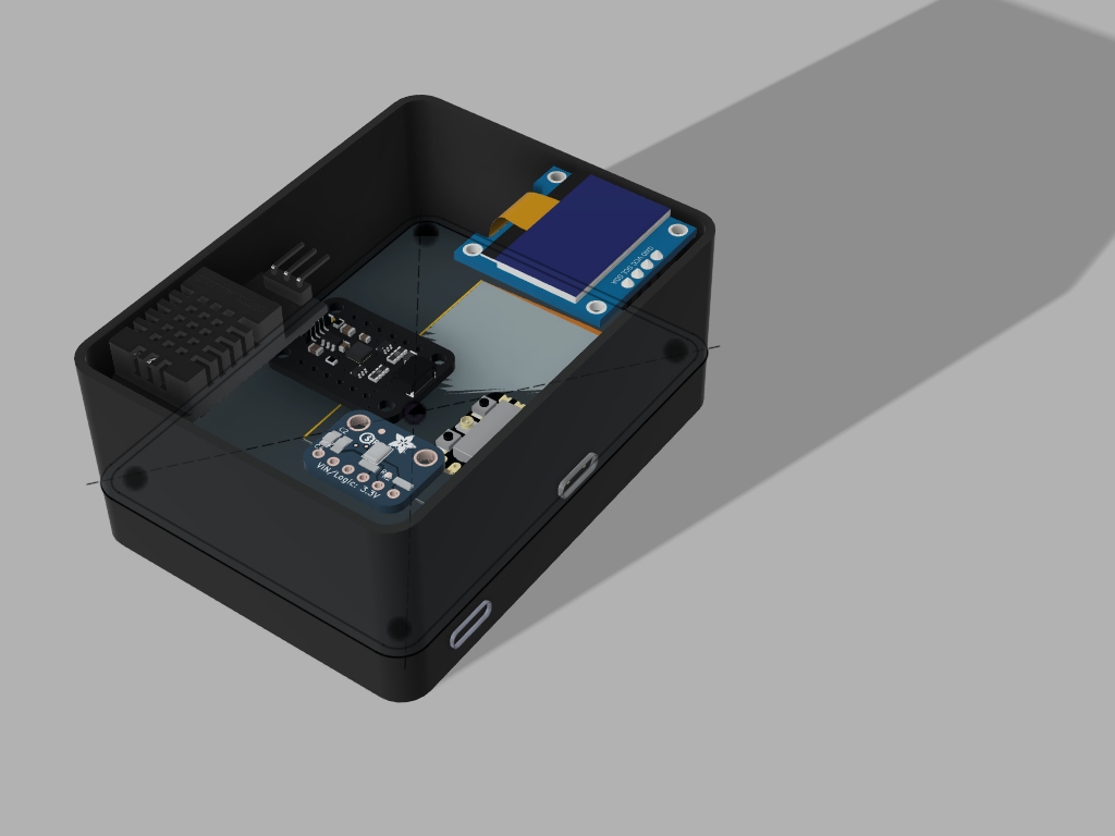
And this is the new box, which is smaller than the original dimension:
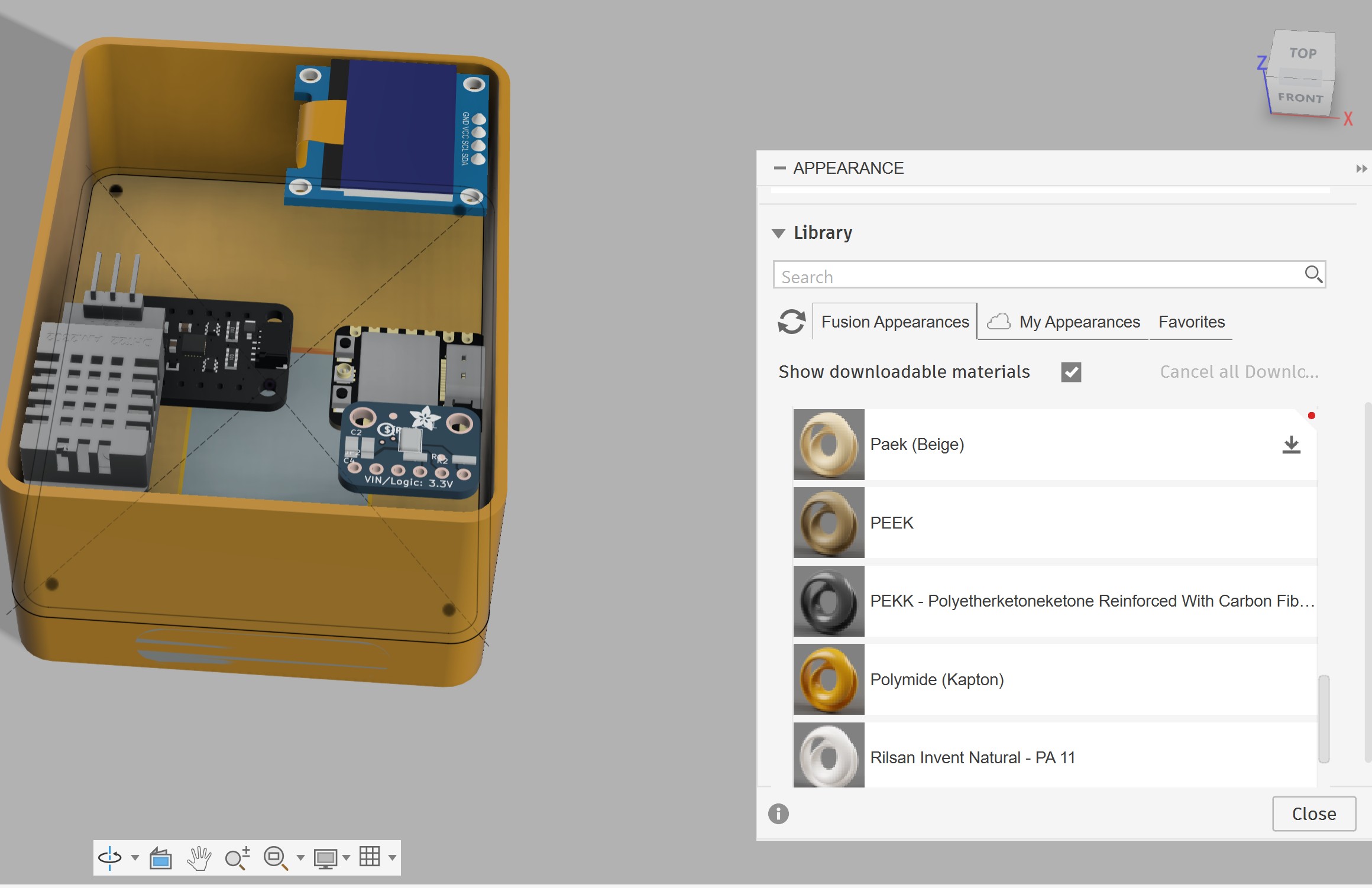
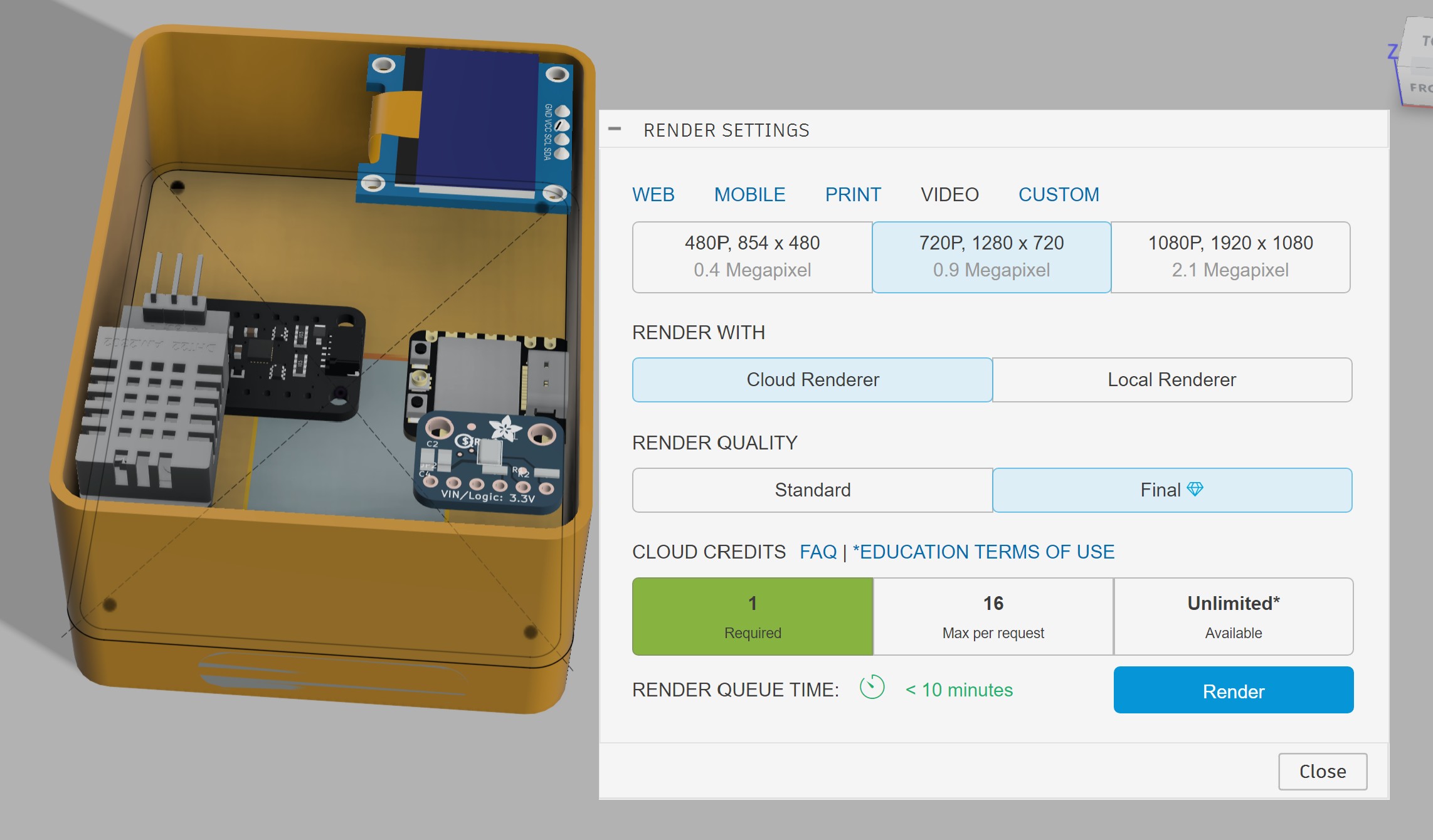
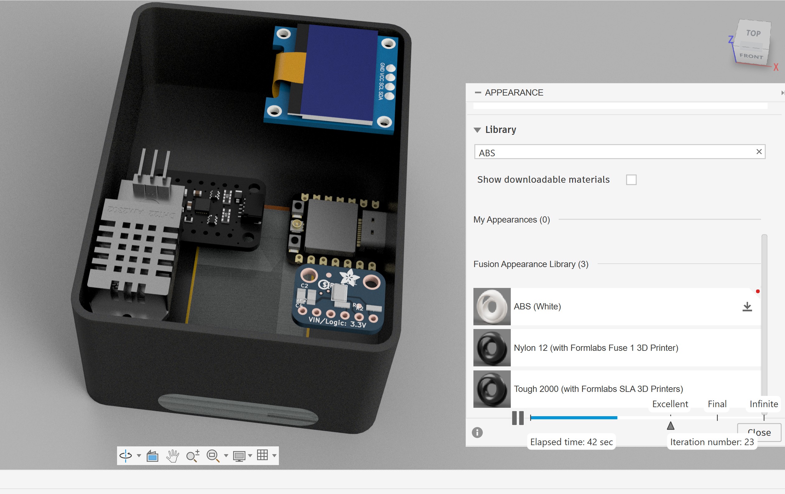
I switched from the Design workspace to the Render workspace:
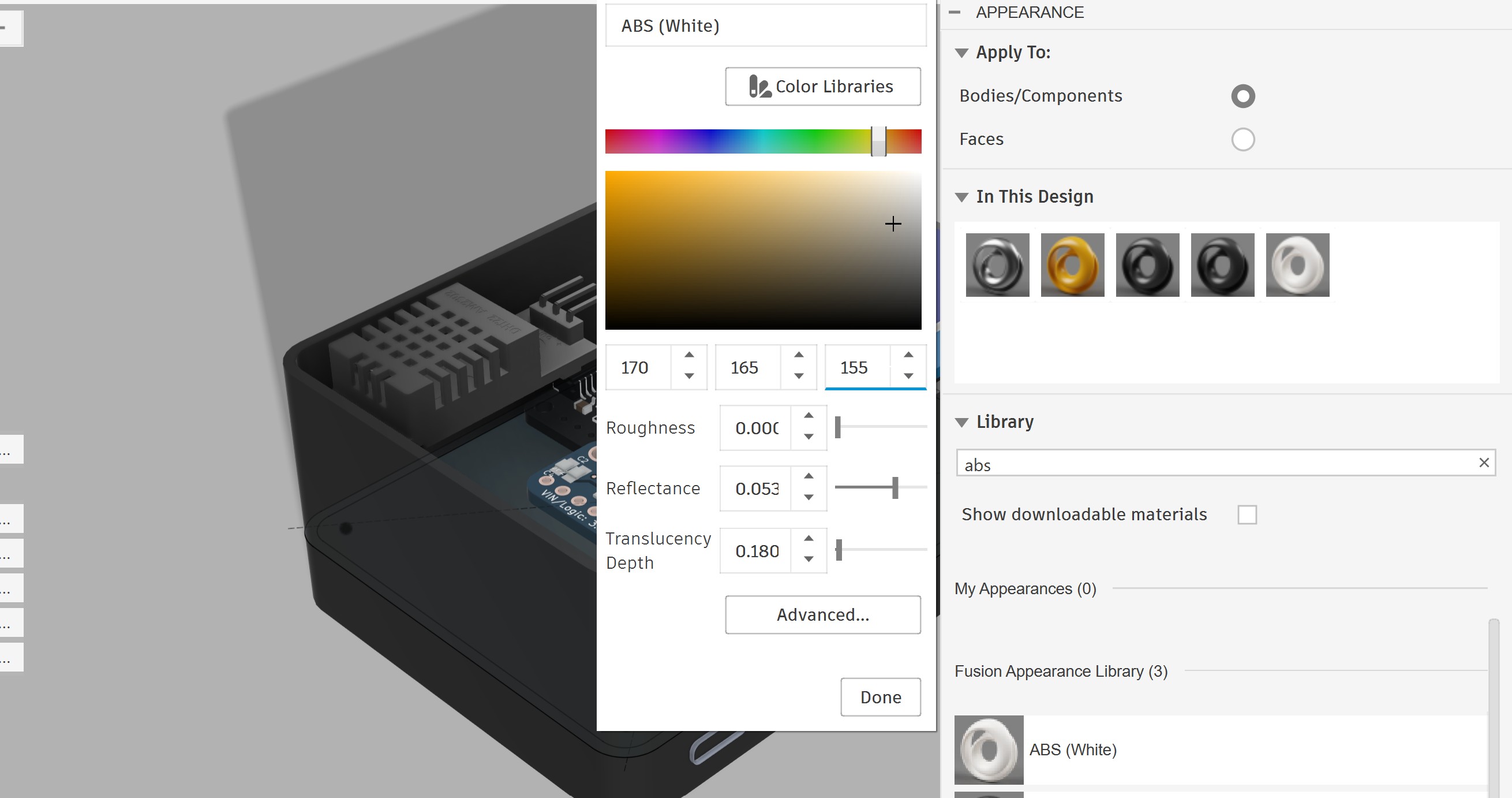
In the Render workspace, I tried different materials, lighting, and environments:
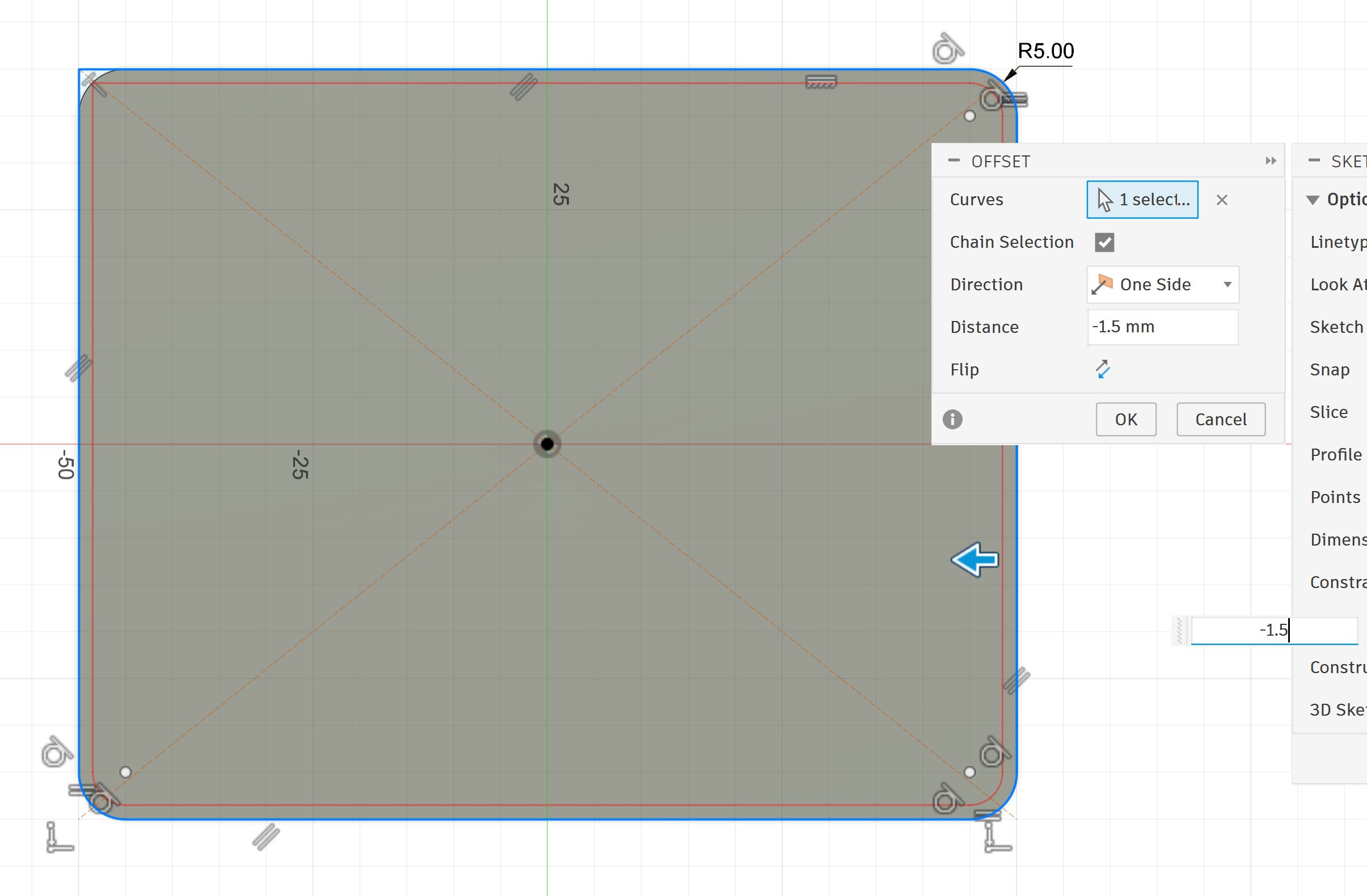
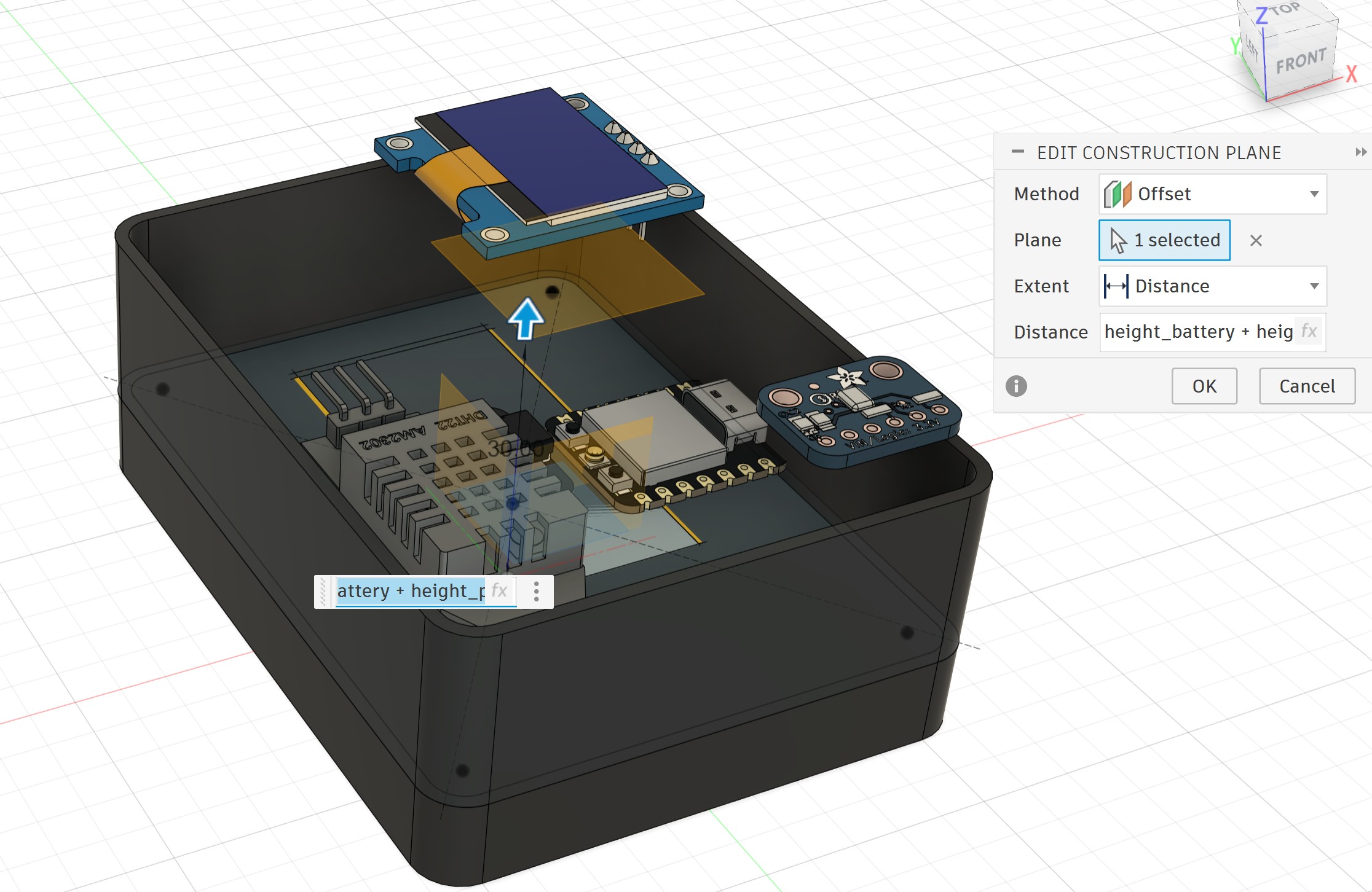
I designed a lid for the enclosure. First, I created an offset plane in the Z direction at the proper height considering the battery and PCB placement.
I used the Project feature to project the wall of the box onto the new plane and created a new sketch:
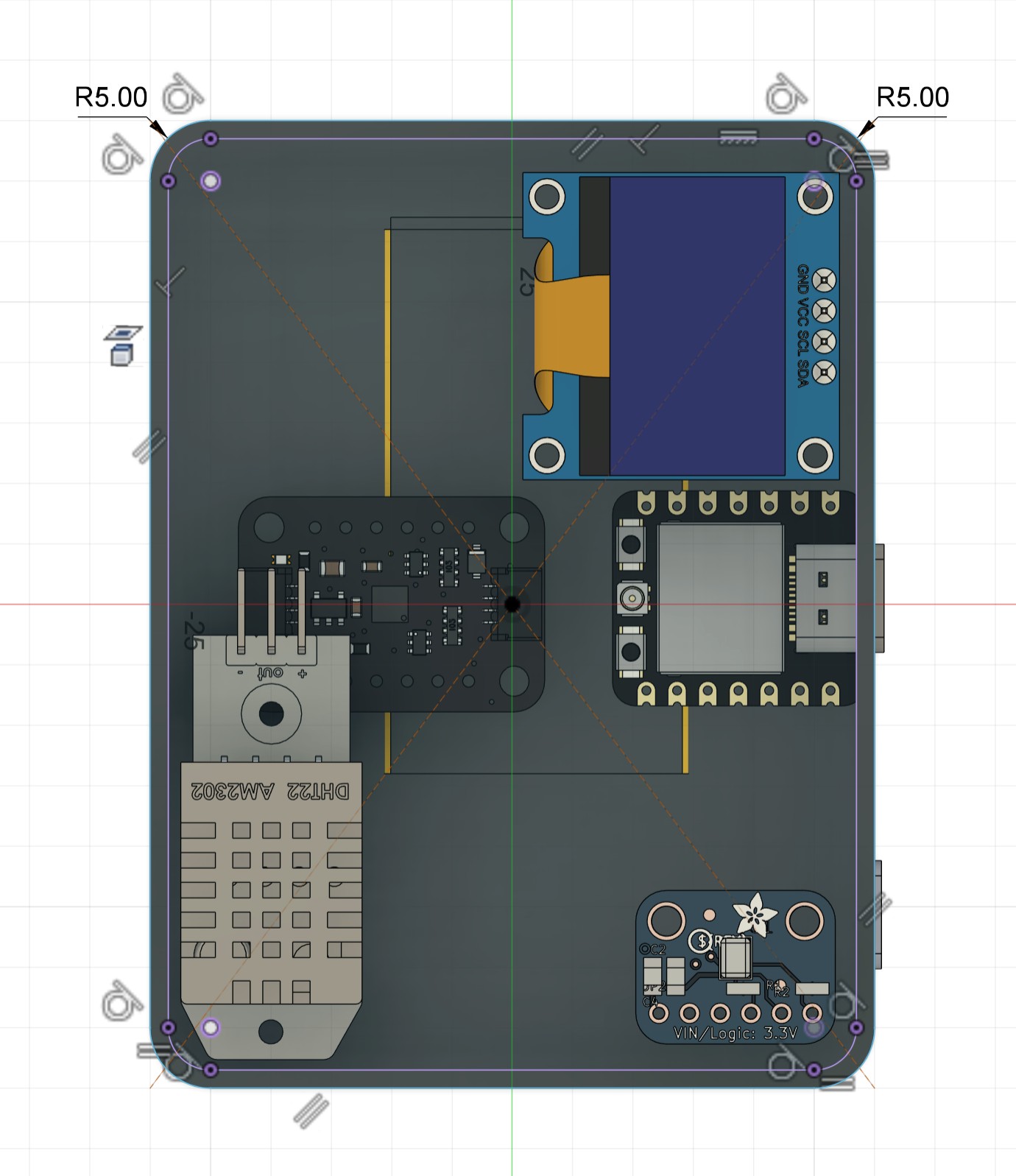
I selected the outer profile of the wall and extruded it upward by 1.5 mm to create the top thickness.
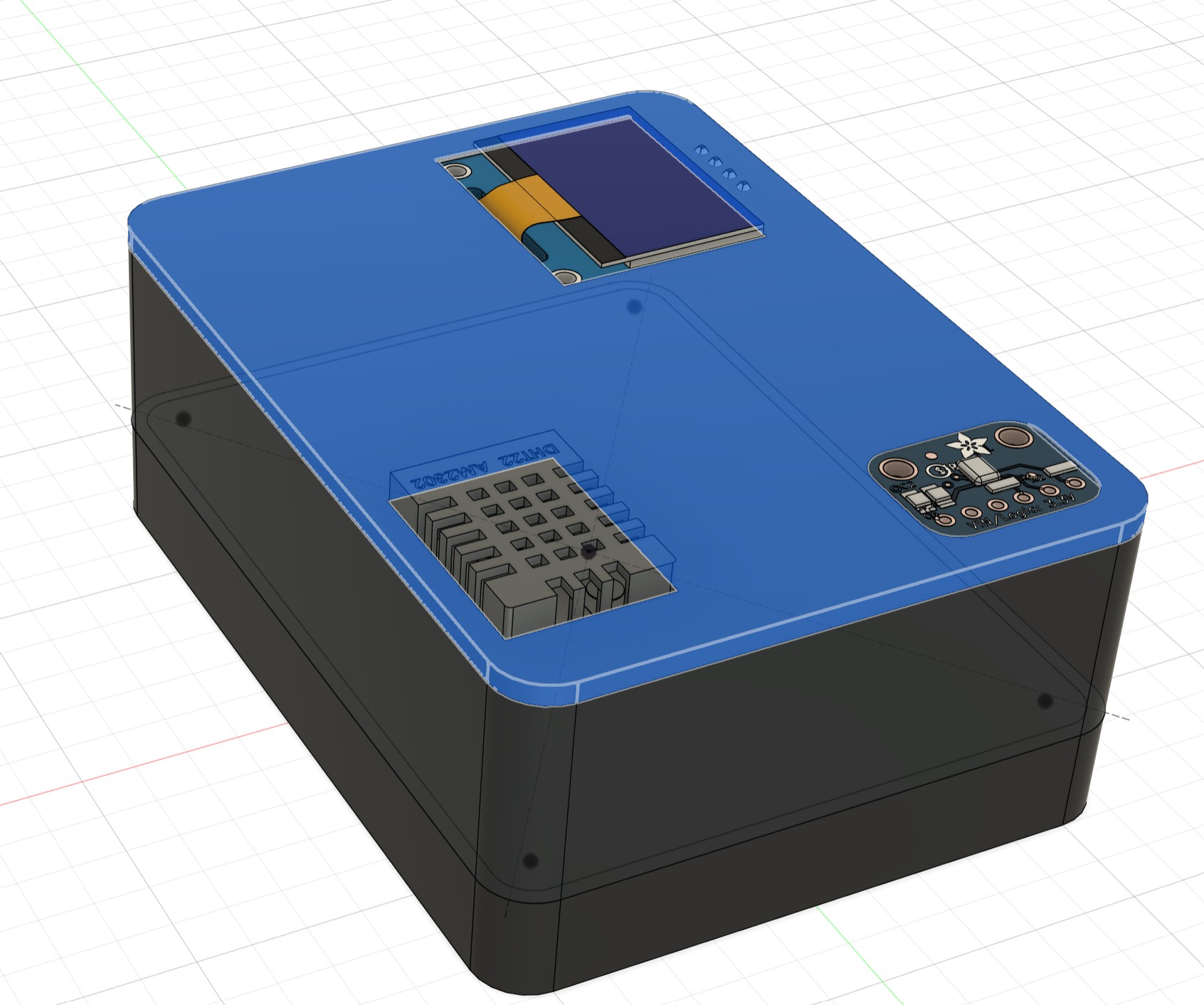
Then, I selected the inner profile of the wall and extruded it downward by 1.5 mm to create the lip that fits inside the box.
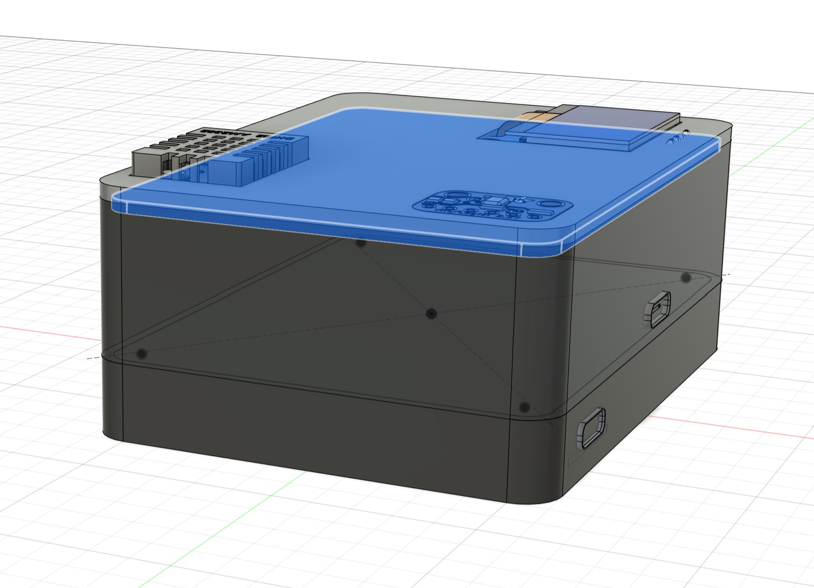
This is the final enclosure with the designed lid:
Animation - Exploded View
I switched to the Animation workspace and created a simple exploded view of the 3D model to better visualize the assembly.
System Integration Plan
The main goal of this week's assignment was to integrate all hardware components of my final project into one compact, portable, reliable, and user-friendly device.
Final project title
The title of my final project is:
Portable Sleep Monitoring Device with Focus on Snoring Detection
Integration strategy
All components will be placed inside a 3D designed 3D printed enclosure. The packaging has been carefully planned to achieve maximum portability while keeping the device easy to assemble and maintain.
Key packaging decisions:
The enclosure consists of three main parts:
- Bottom compartment: Dedicated space for the LiPo battery and MRA193A charging board (easy access for battery replacement or charging).
- Main body: Contains the XIAO ESP32-S3, sensors, and OLED display.
- Lid
Placement of components:
- The OLED will be flush-mounted on the top surface for easy viewing.
- The microphone will have a dedicated opening near the surface to capture sound clearly.
- A ESP32-S3 is the main component of PCB.
- Wiring will be minimized and organized using vertical socket connectors. There is no wiring in my PCB, except the wires from battery to ESP32-S3.
- Battery will be placed under the PCB holder and it can be easy removal.
Current progress in 3D design Fusion 360:
- I created a parametric enclosure.
- Imported real STEP files of components from GrabCAD.
- Adjusted the size few times to make the device as compact as possible.
- Aligned and placed all components.
- Created multiple render views with different materials.
- Designed a lid
Future Improvements
- Checking wiring and connectors
- 3D printer of the first designed to test the real assembly and making final adjustments.
In this week I tried to explain my final project as a sample to do and learn system integration, and from here I linked this week to my final project.
Reflection
This week I focused on bringing all the pieces of my final project together. I learned how important it is to plan the system integration from the beginning instead of just putting components together at the end.
I really enjoyed working with Fusion 360 to design a compact and practical enclosure. I started with a bigger enclosure and slowly made it smaller after placing the real components. This process taught me how to think about space, organization, and user comfort at the same time. Making the device small and light was one of the most important goals because the sleep monitor needs to be easy to carry and comfortable to use every night. I also learned the value of using real STEP files from GrabCAD. It helped me understand the actual size and shape of the parts, so I could adjust the design properly. Designing the lid with a proper lip for good fit was another useful skill I practiced.
Overall, this week helped me see my project as a complete product, not just separate electronics. I became more aware of how packaging, component placement, and usability all affect each other. I feel more confident now about finishing the final project because the main structure is ready and I have a clear plan for assembly.