Week 12 | Mechanical design, machine design
Overview
This week we designed and built a machine that incorporates the following features:
- Mechanism
- Actuation
- Automation
- Function
- User interface
- Build the mechanical parts and operate it manually
And additionally and more importantly: - Document the group project and individual contribution
We decided to create a Intelligent sorter that can detect objects based on their colors. The machine uses image processing to identify the color of objects placed on a rotating platform and sort the objects with targeted color into bin using a servo-controlled arm. The link to the Group Work.
Individual Assignment & Contribution
I contributed to both the mechanical design and the overall integration of the machine. Below is a detailed documentation of my work structured according to the assignment requirements.
1. Mechanism
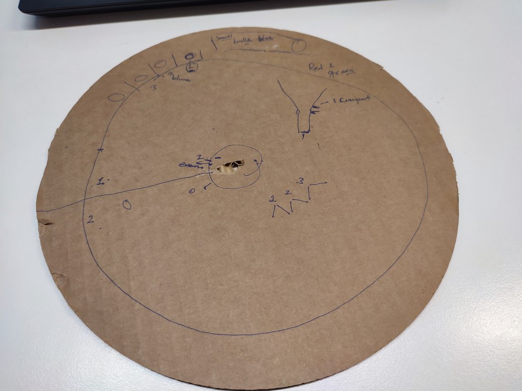
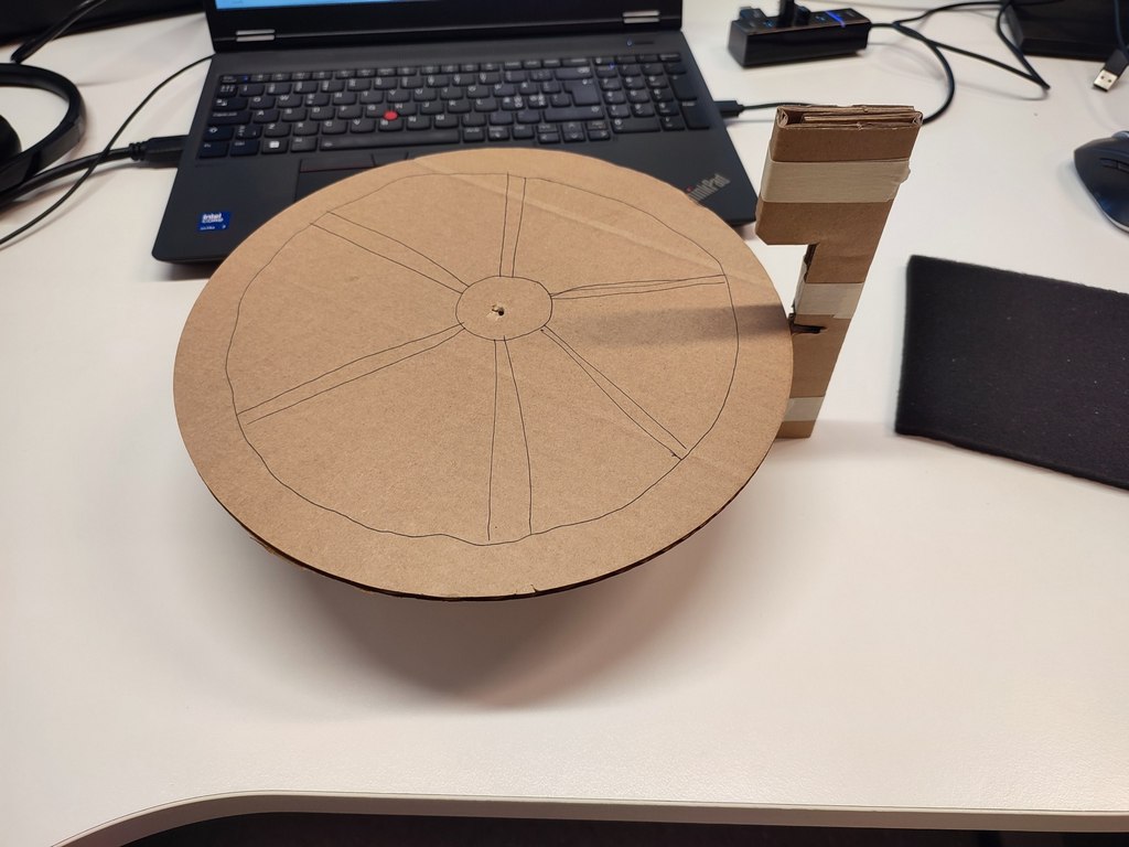
For the mechanical parts, we first created quick cardboard prototypes to test the concept and dimensions. After finalizing the design, we fabricated the parts using laser cutting and 3D printing.
The main mechanical components include:
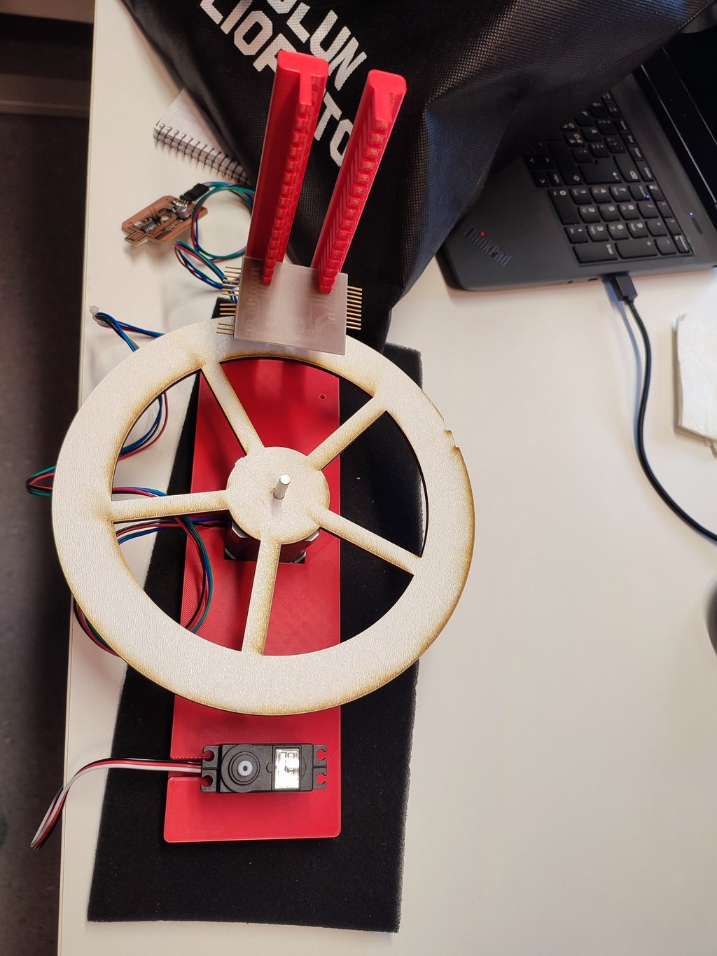
- A rotating platform (plate) for carrying objects mounting on the stepper motor
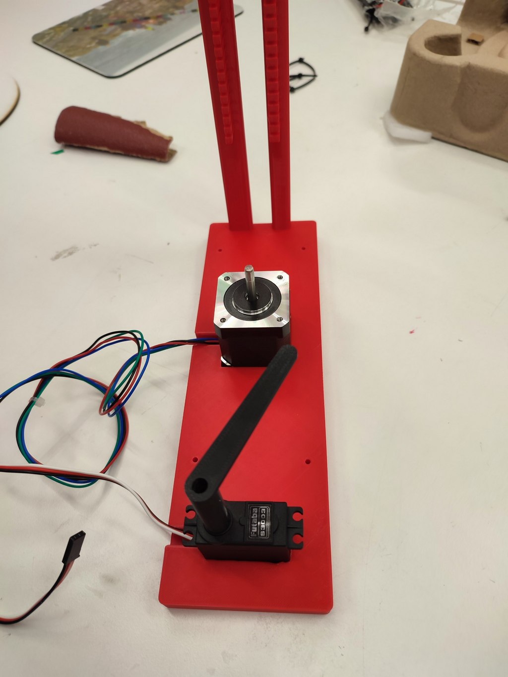
- A 3D-printed stand to hold the stepper motor, servo motor, a vertical leg to hold the camera
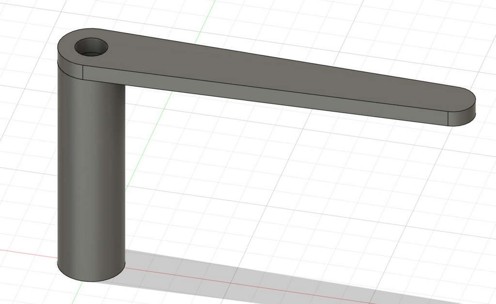
- L-shaped arm mounted on the servo to push objects into collection bin
Making the Platform and Stand
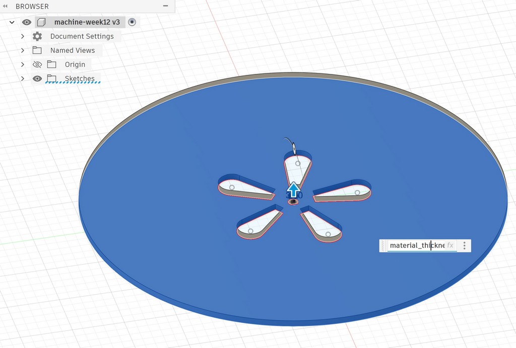
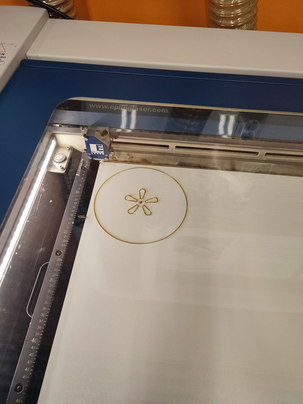
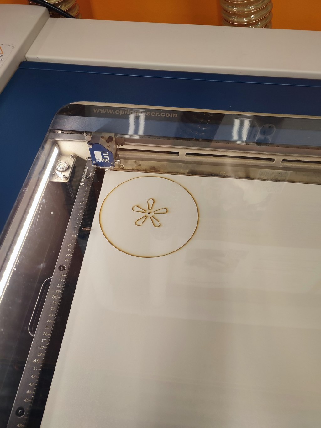
I designed the rotating platform in Fusion 360. The plate has a diameter of 200 mm with hollow cones on the surface of it. The thickness was set to 3 mm to match the plywood available in the lab.
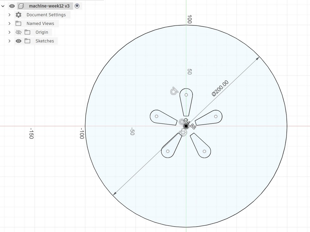
Using the laser cutter, I cut the platform.
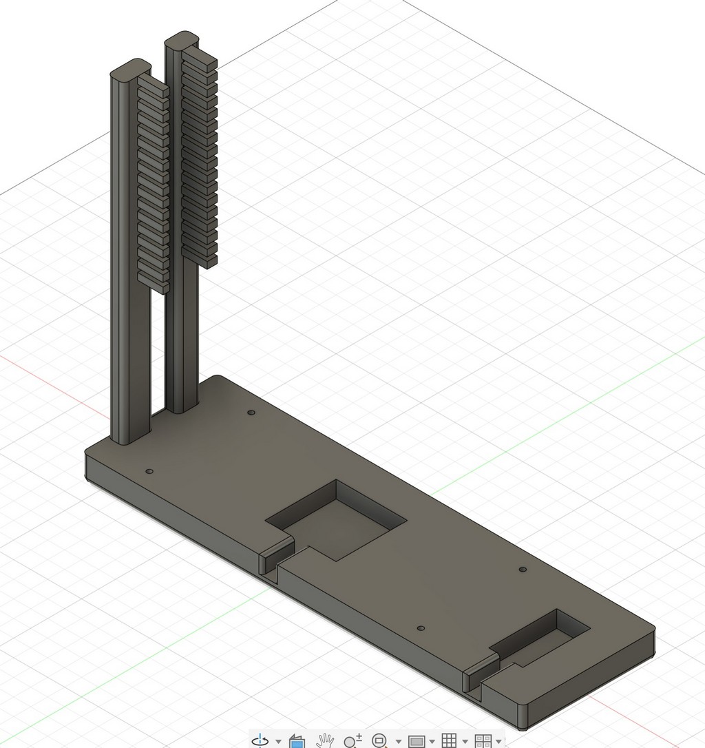
I also designed and 3D printed the main stand. It holds the stepper motor in the center, provides space for the servo motor with the L-shaped arm, and includes a leg for mounting the camera.
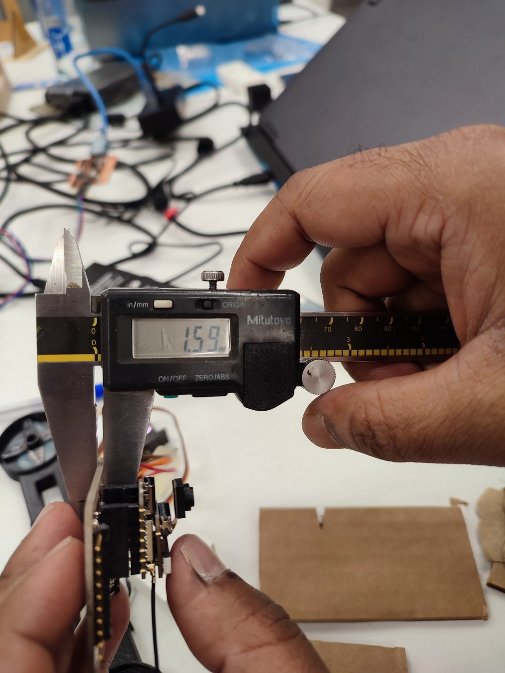
Before modeling, I carefully measured the dimensions of the stepper motor, servo motor, and camera board.
In Fusion 360, I started with the base sketch and extruded the main body.
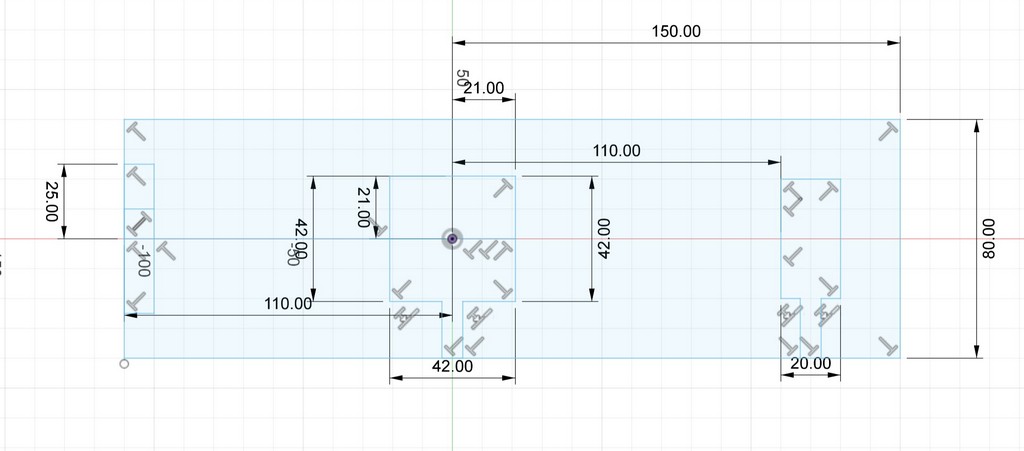
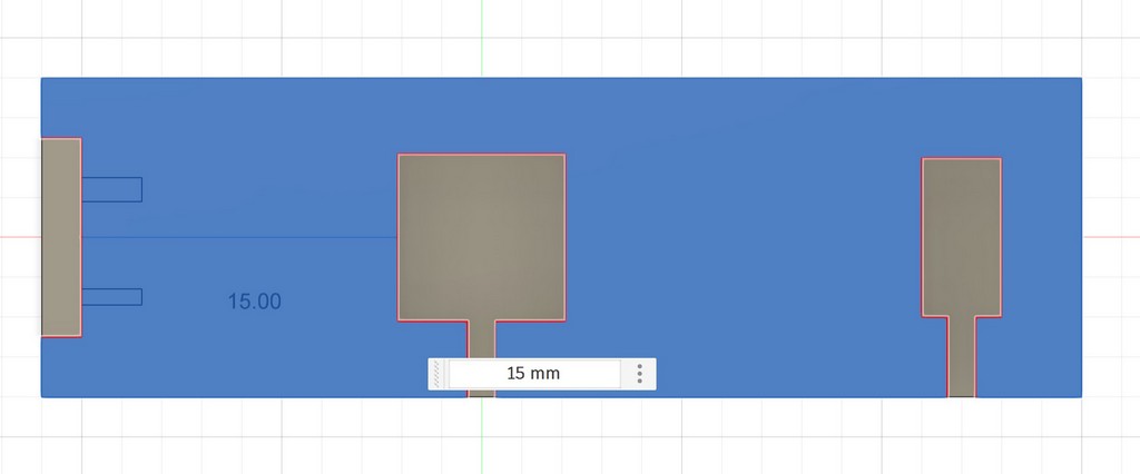
I added a leg for the camera and designed an L-shaped arm for the servo motor.
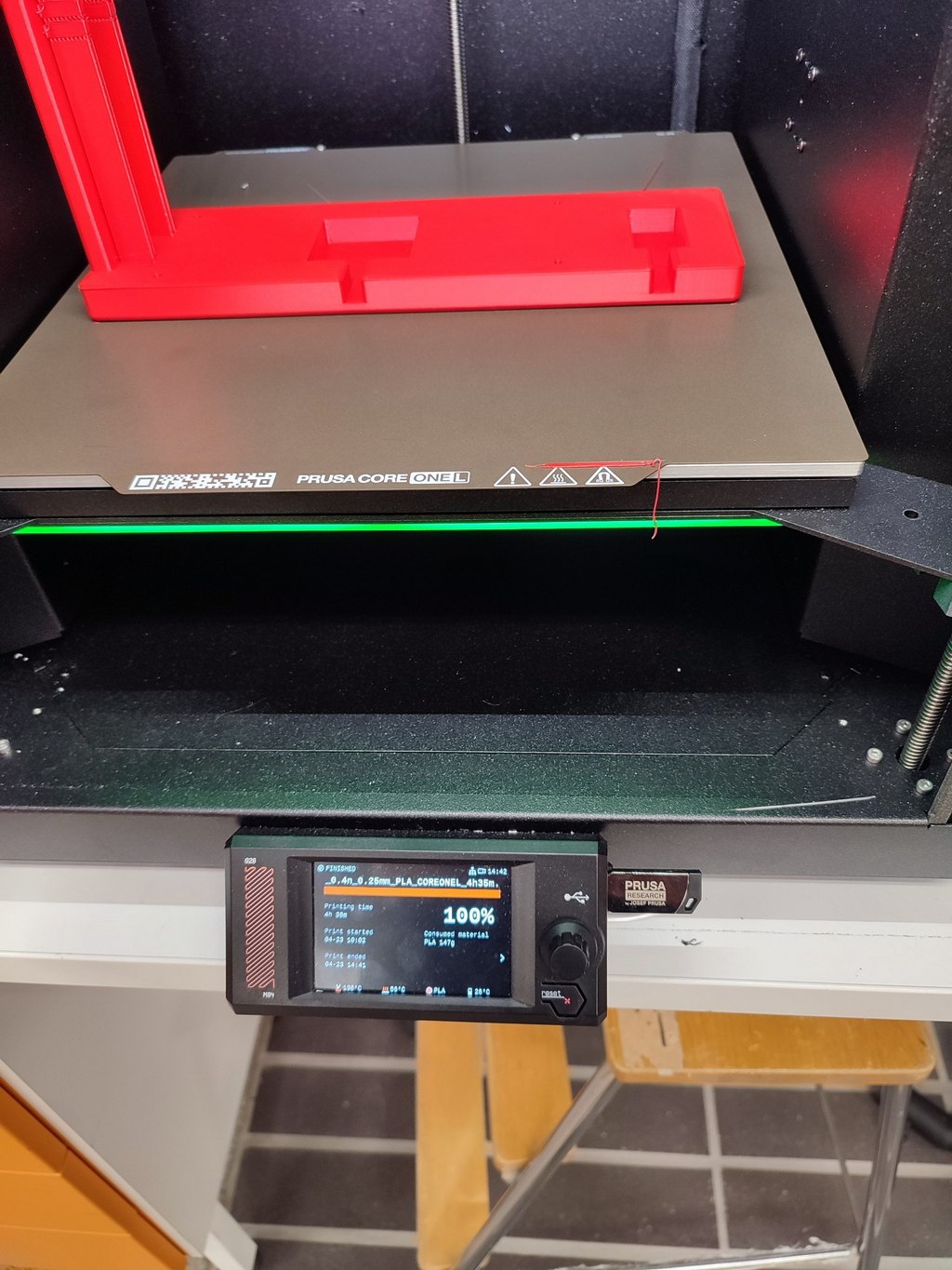
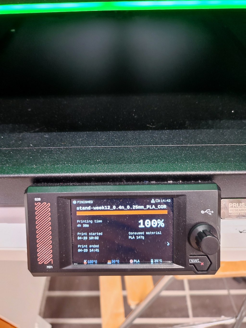
I printed the parts with the Prusa CORE One L printer.
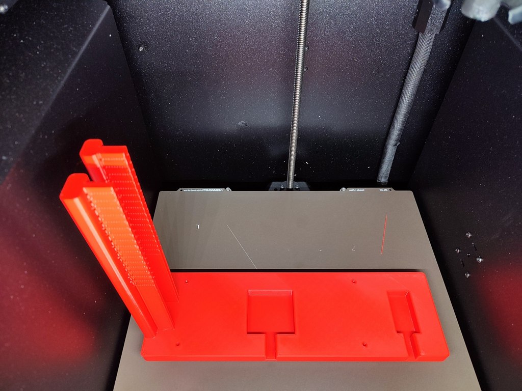
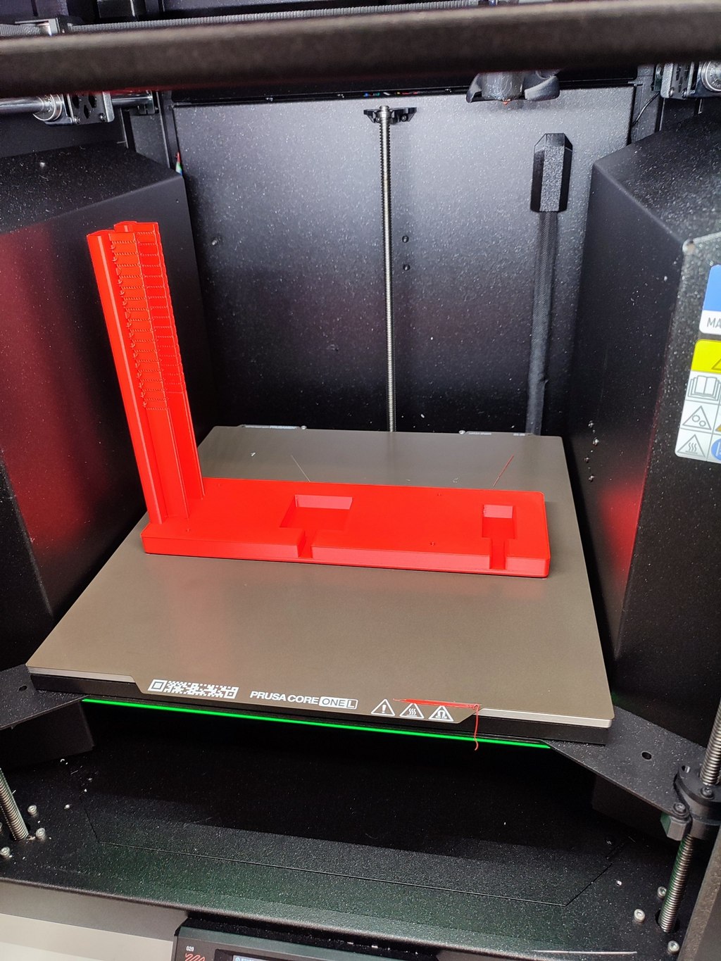
After printing, I tested the fit of the motors and camera. The components aligned well.
I also designed an alternative platform for testing, but we chose the final version with enough space to keep objects.
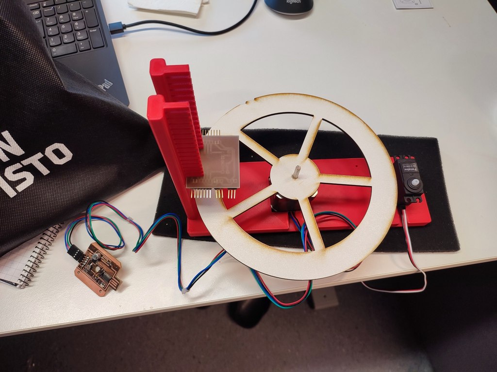
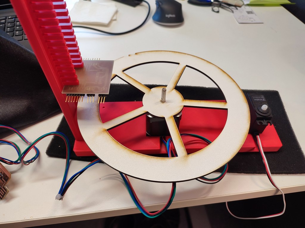
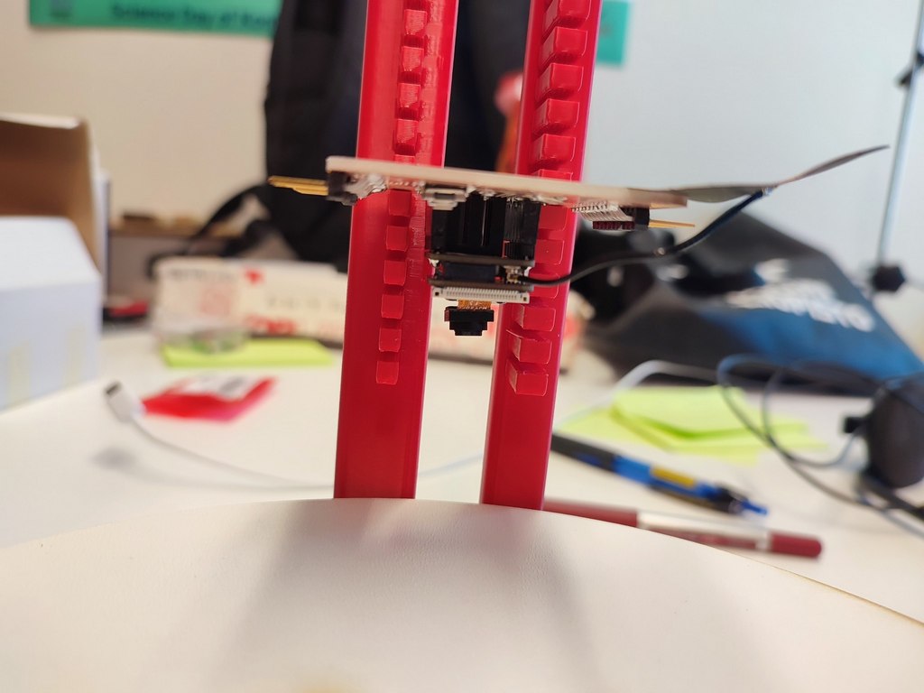
Placement of parts
Here I showed the placements of the mechanical and electronics part.
Stepper and Servo motors
Platform
Electronic board
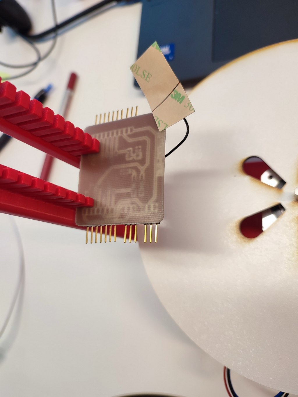
-Ccamera
2. Actuation
Actuation is responsible for the physical movement of the machine. We used two actuators. The stepper motor is fixed in the center of the 3D-printed stand, while the servo is mounted on the side for optimal pushing motion.
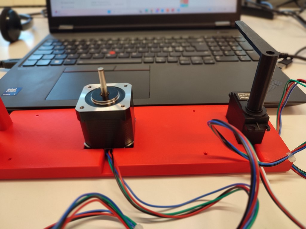
Stepper Motor (NEMA 17)
We used RoHS 17hs19-2004s1, stepper motor.
Rotates the main platform to move objects under the camera. It is mounted centrally under the plate and driven directly by its shaft. Controlled via a stepper driver and powered by 12V.
Servo Motor (S3003)
This servo Controled the L-shaped arm that pushes sorted objects into the bin.
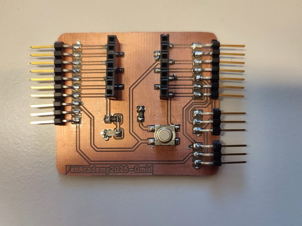
The servo motor derived using the PCB board which I made in Electronic production week, ank controlled with ESP32-S3.
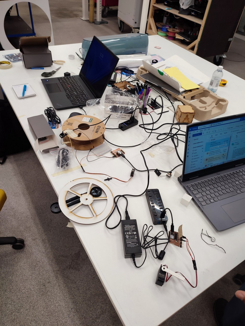
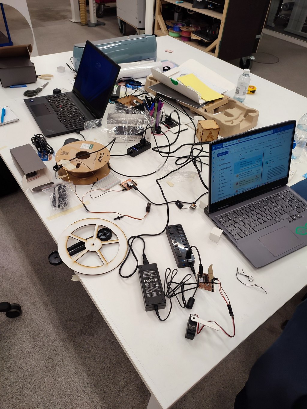
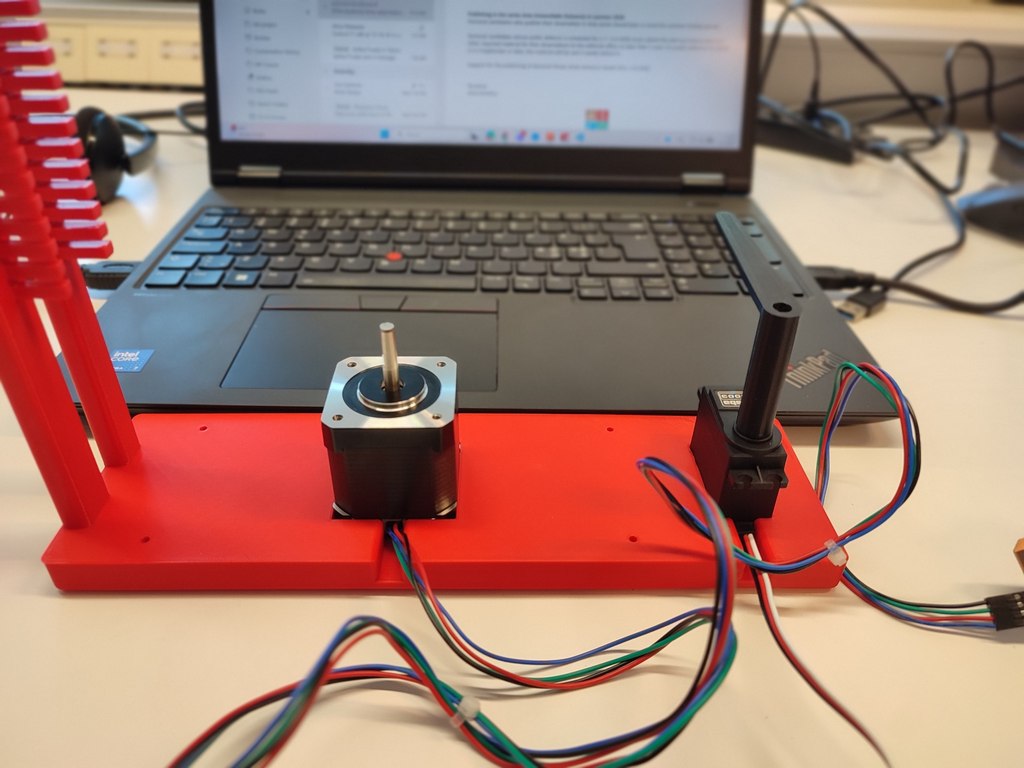
Driving the stepper motor
Step 1:
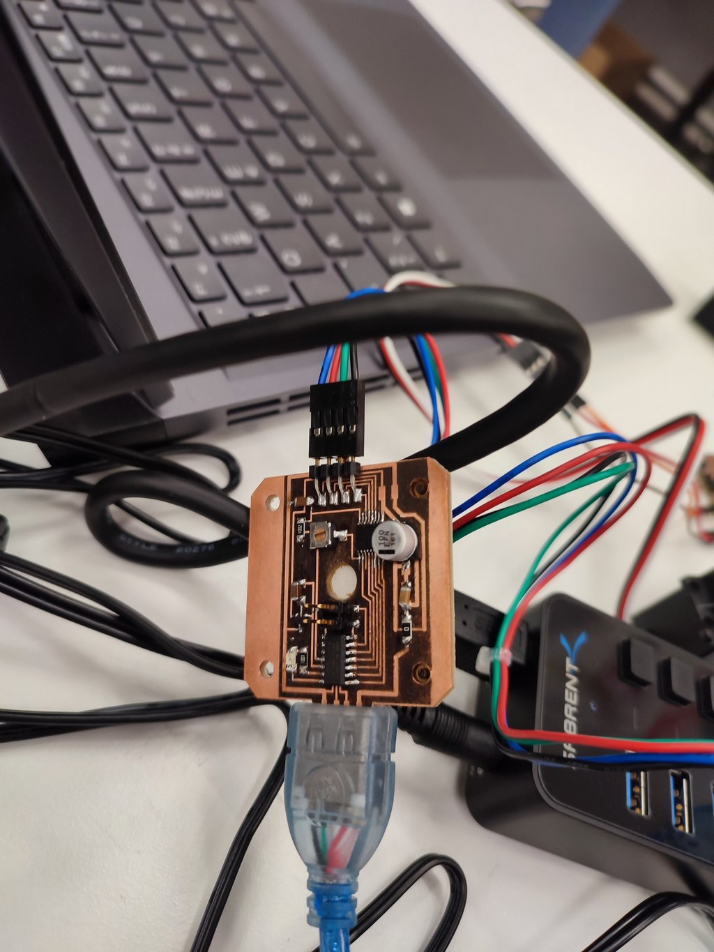
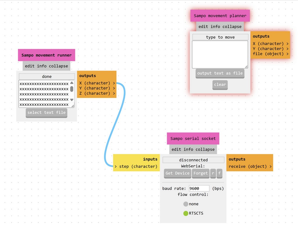
We used Mods Project to control the stepper motor from the computer.
Step 2:
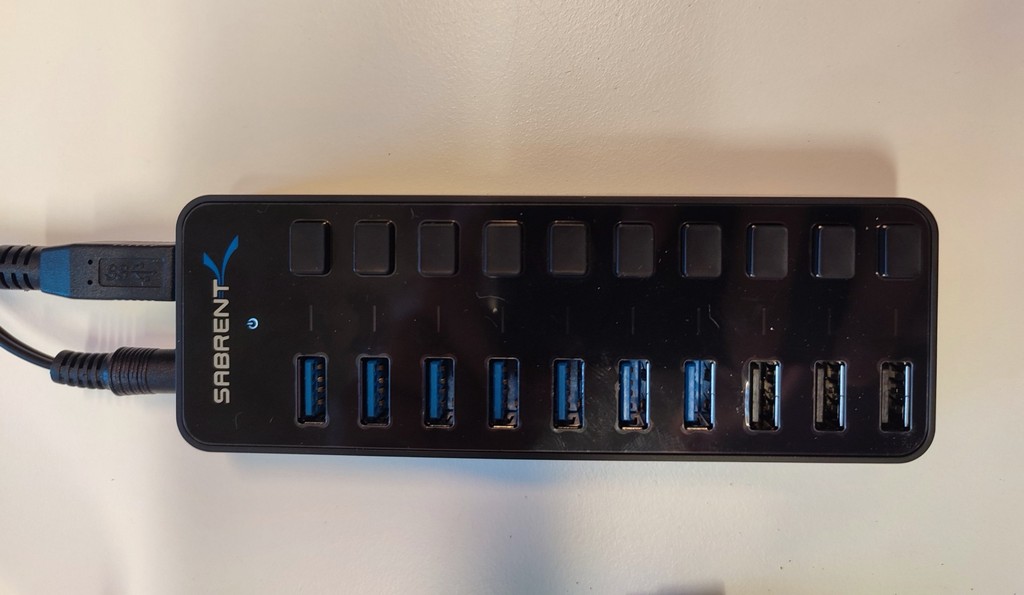
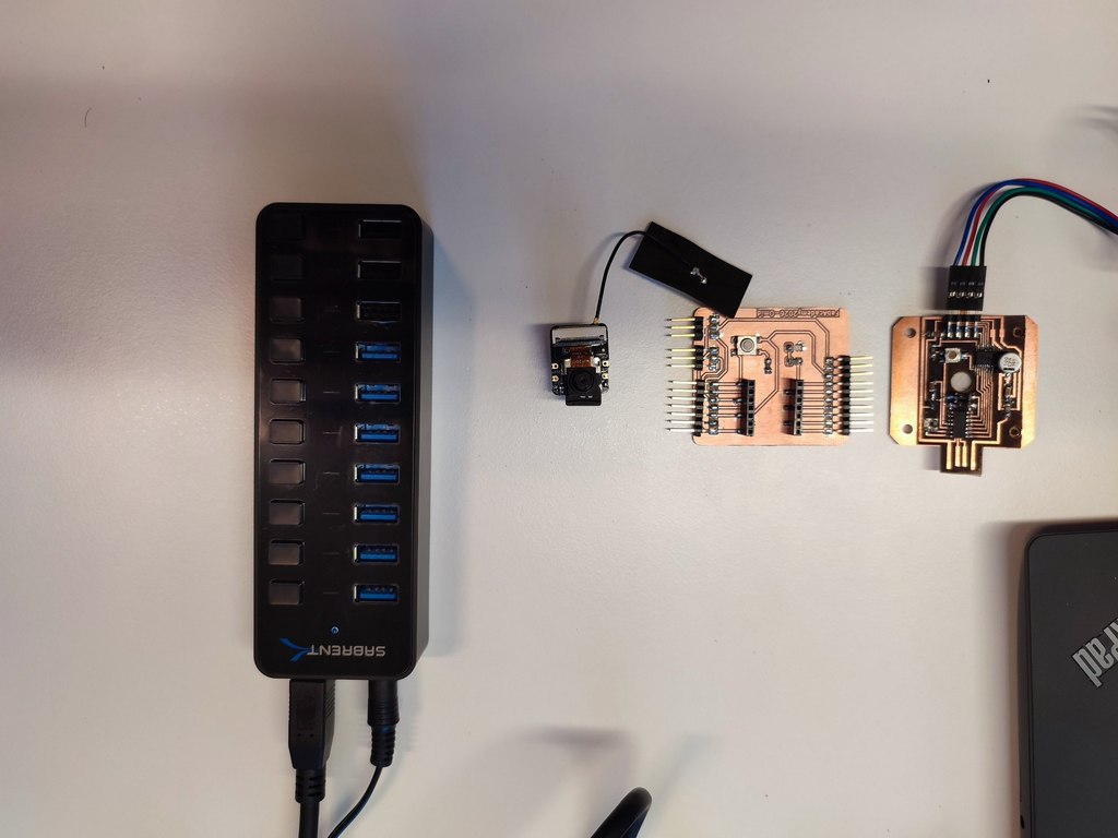
To provide power for the setup, we used a Sabrent 60W 10-Port USB 3.0 Hub with a 12V/5A power adapter.
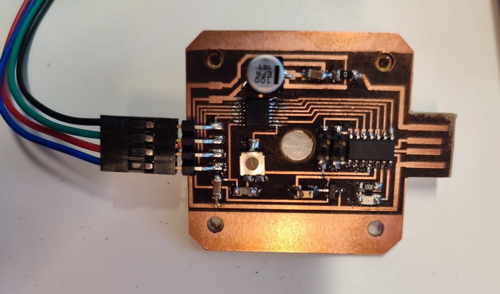
Step 3:
We connected the setup using the driver board that Jani made.
3. Automation
The machine integrates sensing, processing, and control to operate with minimal human intervention.
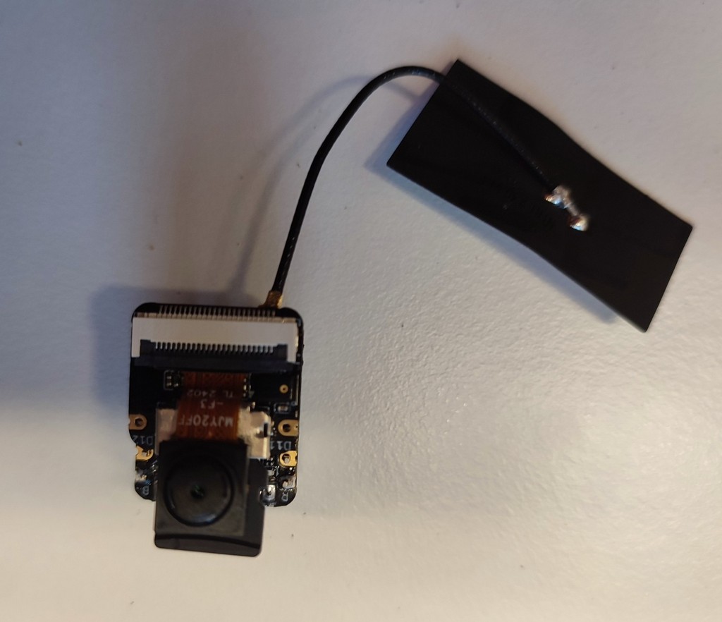
We used the custom PCB I designed during Electronic Production week, paired with an ESP32-S3 microcontroller that includes a built-in camera.
The electronic part we used in the machine.
- Microcontroller: ESP32-S3
- Vision: Built-in ESP32 camera
- Color Detection: Color detection algorithm (tinyML-algorithm)
- Control: Arduino IDE
- Interface: WiFi web interface for start/stop and monitoring
System Workflow
- An object is placed on the rotating platform.
- The stepper motor rotates the platform to position the object under the camera.
- The ESP32 camera captures an image.
- A color detection algorithm (tinyML-algorithm) identifies the dominant color.
- Based on the color, the servo motor started to act (make a block at degree) pushes the object down from platform.
- The process repeats for the next object.
4. Function
Although built as a prototype, the machine has several practical applications:
1️⃣. Industry & Manufacturing
- Sorting parts by color on production lines
- Quality control (verifying correct product color)
2️⃣. Packaging
- Automated sorting of products (e.g., colored bottles or caps)
3️⃣. Agriculture & Food Processing
- Separating ripe/unripe produce
- Detecting defects based on color
4️⃣. Recycling
- Sorting plastics and other materials by color
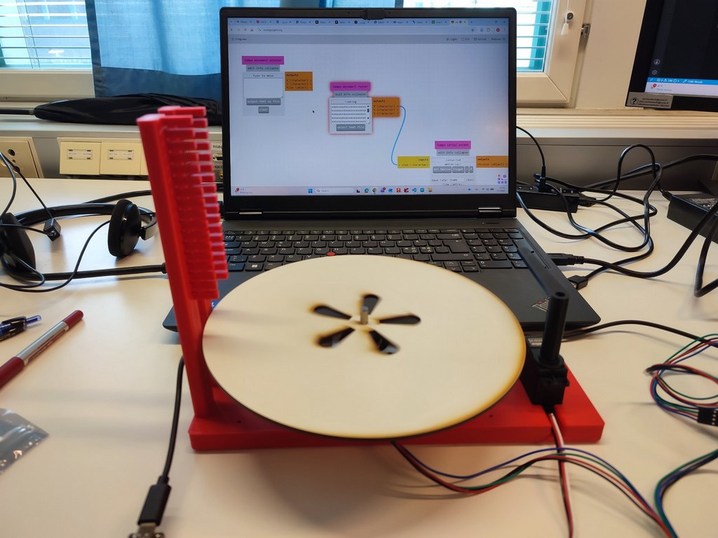
5. User Interface
The machine features a simple web-based user interface accessible via WiFi. Through the ESP32-S3, users can:
- Start and stop the sorting process
- Monitor real-time camera feed
Reflection
This week was one of the most comprehensive and challenging assignments in the Fab Academy. Designing and building a functional machine from scratch required close collaboration between mechanical design, electronics, and programming.
My main contribution was in the mechanical design, creating the rotating platform and the 3D-printed stand that integrates all components cleanly. I learned the importance of accurate measurement, tolerance management, and considering assembly during the CAD phase. The transition from cardboard prototypes to final parts helped us catch design issues early.
Integrating the mechanical system with the electronics and automation was very rewarding.
The project highlighted how important iteration is in machine design. Overall, this week strengthened my ability to contribute to multidisciplinary hardware projects and reinforced the full cycle of digital fabrication.