Introduction
In this assignment, the objective was to control an output device using a microcontroller over a wireless network. To achieve this, I reused the custom development board that I designed and fabricated during the Electronics Production week (Week 06). The board is based on the Seeed Studio XIAO ESP32-C3 microcontroller and provides integrated WiFi connectivity, making it suitable for networking and communication applications.
The custom board developed in Week 06 was originally designed as a general purpose ESP32-C3 platform with access to GPIO pins, power connections, and programming interfaces. For this assignment, the same board was repurposed as a wireless controller for a servo motor, demonstrating how a previously fabricated embedded system can be integrated into a networked application. This approach allowed me to build upon earlier work rather than relying on an off-the-shelf development board.
Communication between the laptop and the ESP32-C3 board was established using a mobile phone hotspot. The ESP32 operated as a web server, while the laptop acted as a client. Through a web browser, commands could be transmitted over WiFi to control the position of the servo motor and activate automatic motion modes. This demonstrates the integration of embedded electronics, wireless networking, and actuator control within a single system.
The complete design and fabrication process of the custom ESP32-C3 board can be found in the Week 06 documentation: Week 06 – Electronics Production.
The control was implemented using WiFi, where the ESP32 acts as a web server. A web interface allows controlling the servo motor position (0°, 90°, 180°) and also enables an automatic sweep mode.
Seeed Studio XIAO ESP32-C3
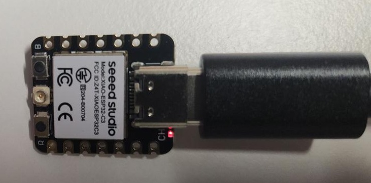
The XIAO ESP32-C3 is used as the main controller. It provides WiFi connectivity and generates PWM signals required to control the servo motor.
The Seeed Studio XIAO ESP32‑C3 is a compact and low‑power microcontroller development board designed for embedded systems and Internet of Things (IoT) applications. It is based on the ESP32‑C3 chip, which features a 32‑bit RISC‑V processor with built‑in Wi‑Fi and Bluetooth Low Energy (BLE) connectivity, making it suitable for wireless communication projects. Despite its very small form factor, the board provides multiple GPIO pins, supports analog and digital inputs/outputs, and includes USB‑C connectivity for power, programming, and serial communication. The XIAO ESP32‑C3 is compatible with popular development environments such as the Arduino IDE and ESP‑IDF, enabling rapid prototyping and experimentation. Its low energy consumption, and have integrated wireless capabilities.
External Antenna
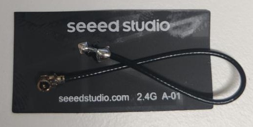
An external antenna is connected to improve WiFi signal strength and ensure stable communication during wireless control.
Servo Motor
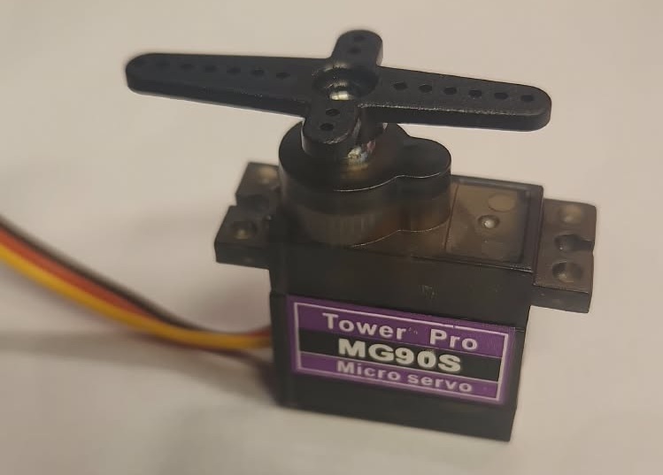
The servo motor is used as the output device. It rotates between 0° and 180° based on PWM signals generated by the ESP32.
Wiring
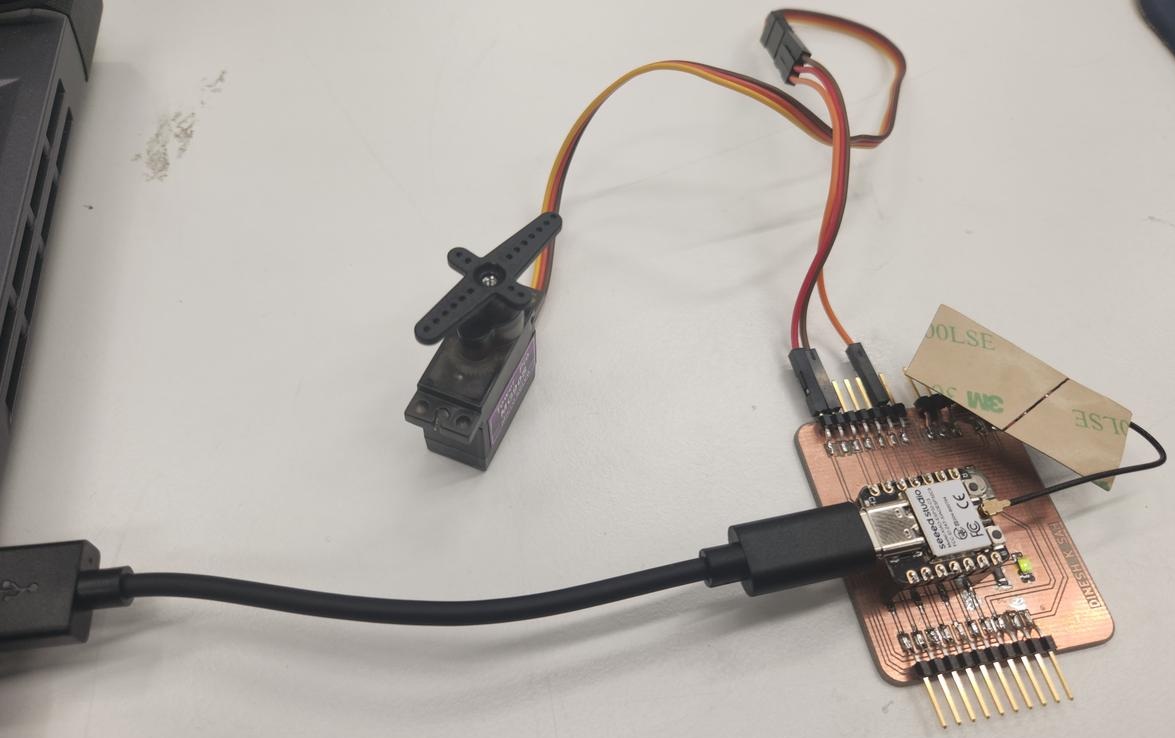
| Servo Wire | Connection | Function |
|---|---|---|
| Red | VCC | Power |
| Brown | GND | Ground |
| Yellow | GPIO 8 | PWM Signal |
GPIO 8 is used to generate PWM signals for controlling the servo motor position.
Code
#include <WiFi.h>
#include <ESP32Servo.h>

const char* ssid = "YOUR_WIFI_NAME";
const char* password = "YOUR_PASSWORD";

WiFiServer server(80);

Servo myservo;
int servoPin = 8;

bool loopMode = false;
int pos = 0;
bool forward = true;

void setup() {
  Serial.begin(115200);

  ESP32PWM::allocateTimer(0);
  myservo.setPeriodHertz(50);
  myservo.attach(servoPin, 1000, 2000);

  WiFi.begin(ssid, password);

  while (WiFi.status() != WL_CONNECTED) {
    delay(500);
  }

  server.begin();
}

void loop() {
  WiFiClient client = server.available();

  if (client) {
    String request = client.readStringUntil('\r');
    client.flush();

    if (request.indexOf("/0") != -1) myservo.write(0);
    if (request.indexOf("/90") != -1) myservo.write(90);
    if (request.indexOf("/180") != -1) myservo.write(180);

    if (request.indexOf("/loop_on") != -1) loopMode = true;
    if (request.indexOf("/loop_off") != -1) loopMode = false;

    client.println("HTTP/1.1 200 OK");
    client.println("Content-type:text/html");
    client.println();
    client.stop();
  }

  if (loopMode) {
    myservo.write(pos);

    if (forward) {
      pos++;
      if (pos >= 180) forward = false;
    } else {
      pos--;
      if (pos <= 0) forward = true;
    }

    delay(15);
  }
}
The program uses the WiFi library to connect the XIAO ESP32-C3 to a local wireless network and creates a simple web server on port 80. The ESP32Servo library is used to generate PWM signals required for servo control. Once connected to the network, the ESP32 listens for incoming HTTP requests and interprets specific URLs to position the servo at 0°, 90°, or 180°. An additional loop mode continuously sweeps the servo between the minimum and maximum positions.
For wireless communication, both the laptop and the XIAO ESP32-C3 were connected to the same mobile phone hotspot network. The hotspot credentials (SSID and password) were specified in the Arduino code and used by the ESP32 to automatically join the network during startup.
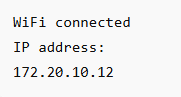
After uploading the program, the Serial Monitor was opened in the Arduino IDE at a baud rate of 115200 bps. Once the ESP32 successfully connected to the phone hotspot, it printed its network information, including the IP address assigned to the device. In this experiment, the ESP32 reported the address 172.20.10.12.
It is important to note that both the laptop and the ESP32 must be connected to the same network in order to communicate with each other. Since both devices were connected to the same mobile hotspot, the web server running on the ESP32 became accessible from the laptop through a web browser.
After obtaining the IP address from the Serial Monitor, the address
http://172.20.10.12 was entered into a web browser on the laptop.
This opened the ESP32 web interface, allowing wireless control of the servo
motor. Successful loading of the web page and immediate response of the servo
confirmed that the network connection and communication between the laptop and
the ESP32 were functioning correctly.
Results
The servo motor was successfully controlled using WiFi. The web interface allowed manual positioning (0°, 90°, 180°) and automatic sweeping using loop mode.