1. Objectives
- Design a 3D printable object that cannot be manufactured subtractively
- Document the design and printing workflow
- Perform 3D scanning of a physical object
- Process and evaluate scanned mesh data
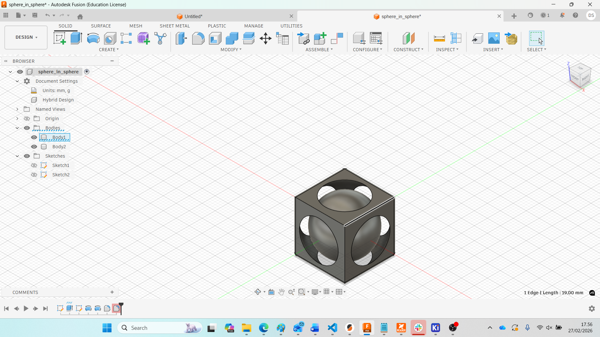
1. Design Concept – Trapped Sphere Inside a Cube
For this week’s assignment, I designed a trapped sphere inside a cube using Autodesk Fusion 360. The objective was to create an object that cannot be manufactured subtractively. The sphere is fully enclosed inside the cube but remains free to move after printing.
To understand the geometric strategy behind trapped designs, I referred to a Fusion 360 tutorial on designing a sphere trapped inside a cube. I recreated the model step-by-step and adjusted parameters according to my design requirements.
Step 1 – Creating the Base Cube
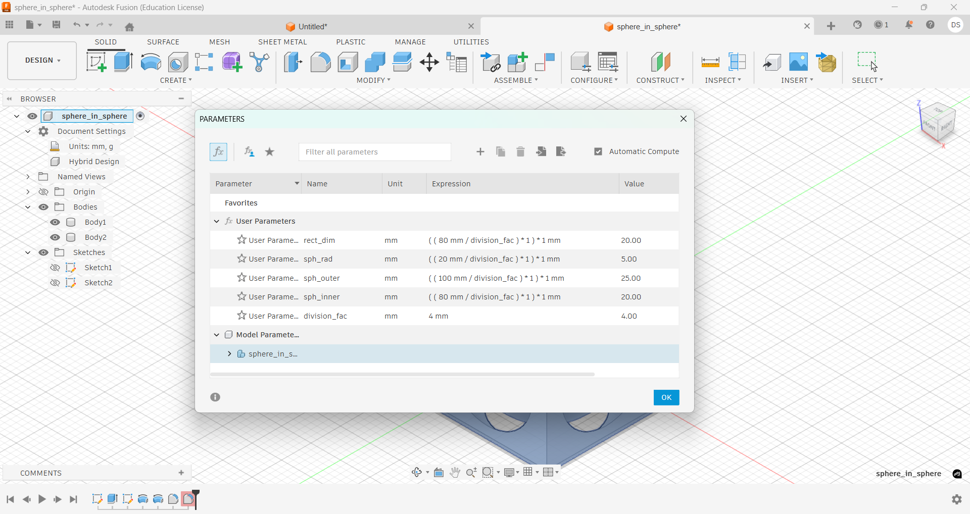
I started by creating a sketch on the Top Plane. Using a Center Rectangle, I created an 80 mm × 80 mm square, constrained at the origin for proper alignment.
.jpg)
The square was then extruded symmetrically to create a total height of 80 mm. Since symmetric extrusion splits equally on both sides, I used a value of 40 mm on each direction.
Step 2 – Creating Sphere Profiles
To generate the sphere cutout, I created a new sketch on the Front Plane. Two center-diameter circles were drawn:
- Outer Circle: Ø100 mm
- Inner Circle: Ø80 mm
The 80 mm diameter matches the cube width. A center line was drawn through the origin to act as the revolve axis.
.jpg)
Unnecessary sketch portions were trimmed to create semicircular profiles.
.jpg)
Step 3 – Revolve Cut (Creating Hollow Cavity)
The outer profile was revolved 360° around the center axis using the Cut operation. This removed material from the cube and created a spherical cavity inside it.
.jpg)
At this stage, the sphere is fully enclosed within the cube but not connected to the cube body.
.jpg)
Step 4 – Creating the Inner Sphere
Next, the inner circular profile (Ø80 mm) was revolved around the same axis using the New Body operation. This created the internal sphere body.
.jpg)
Step 5 – Exporting STL
After verifying the geometry, I exported the model as an STL file:
- File → Export
- Format: STL
- Unit: mm
Download Final STL File
The final processed 3D model can be downloaded below:
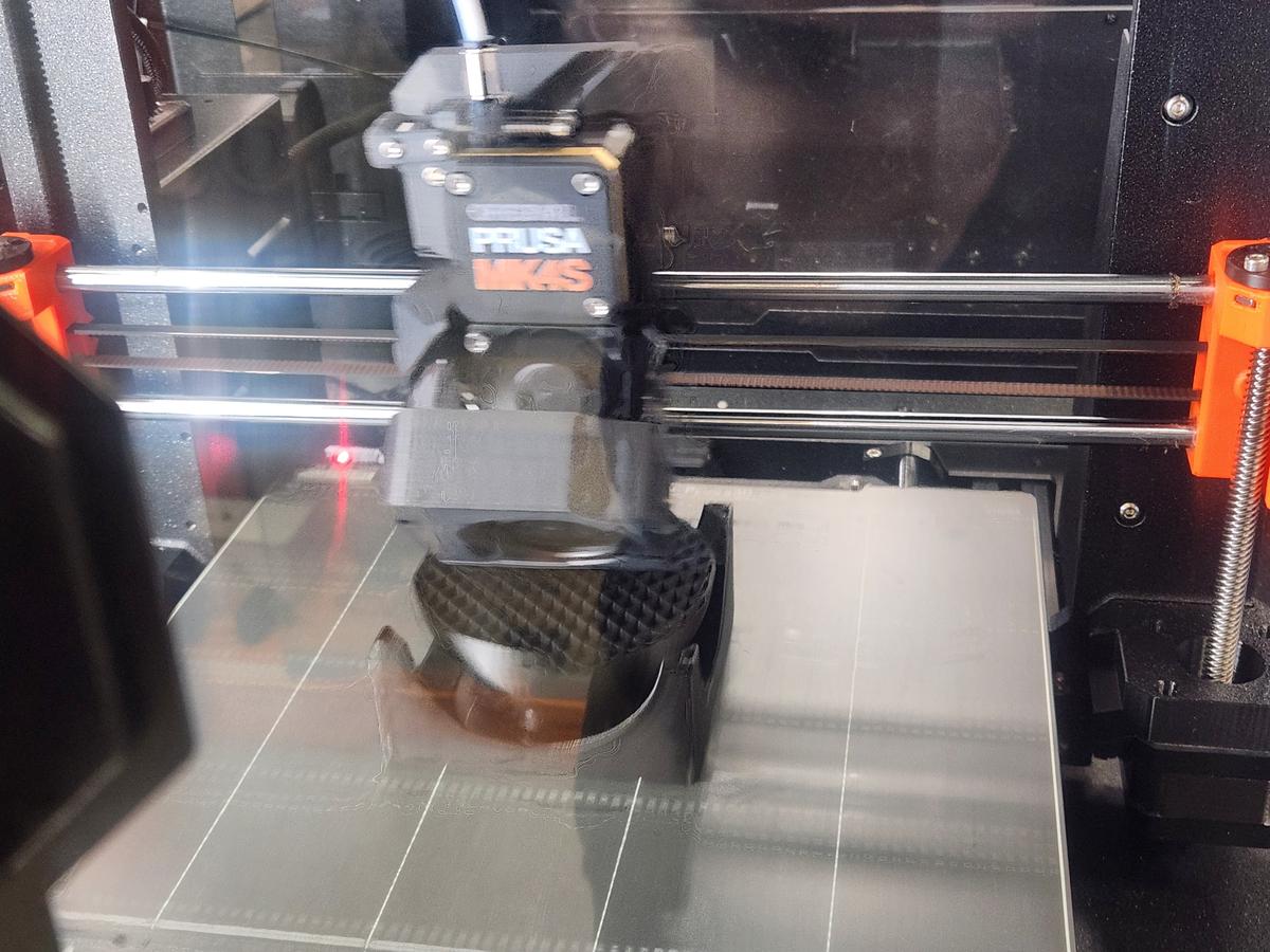
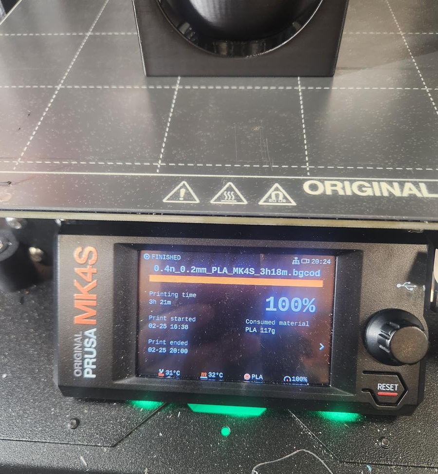
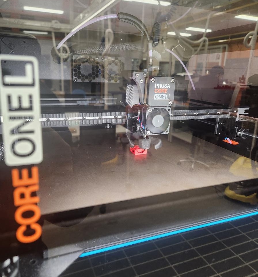
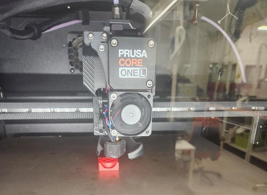
Download STL FileStep 6 – Slicing in PrusaSlicer
The STL file was imported into PrusaSlicer. Settings used:
- Material: PLA
- Infill: 15%
- Supports: Manual (painted support)
- Estimated Print Time: ~2 hours
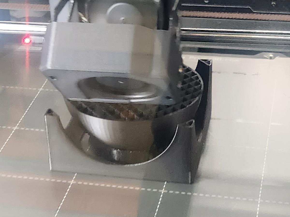
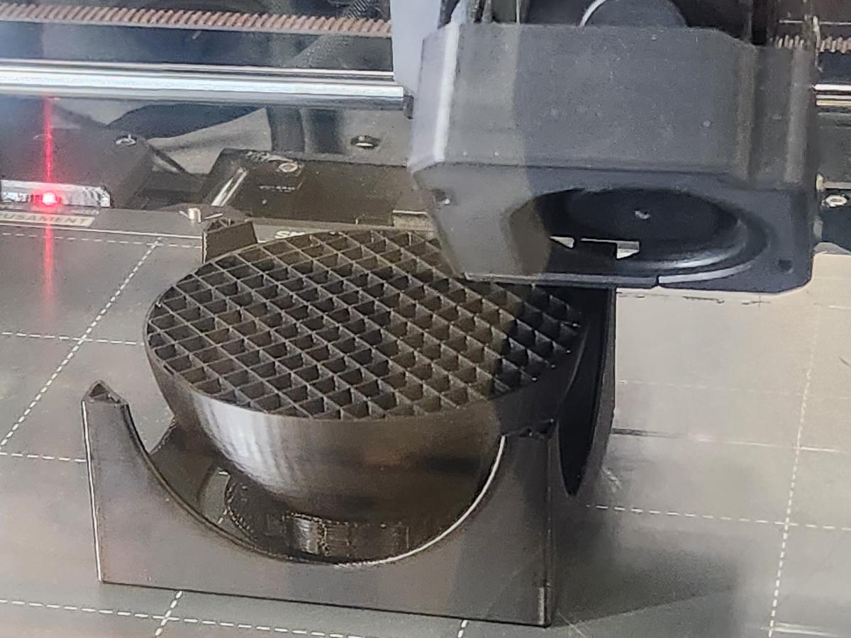
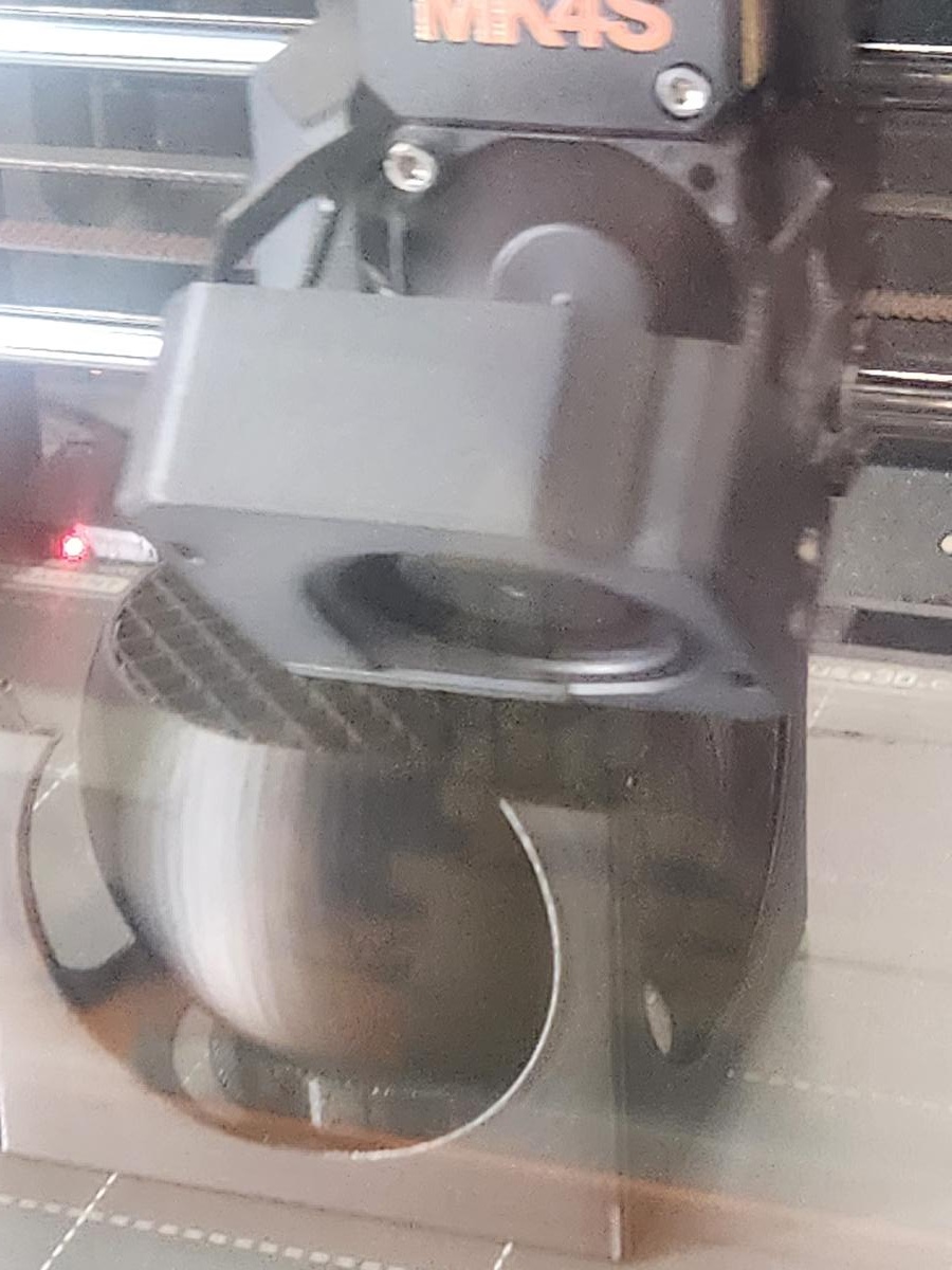
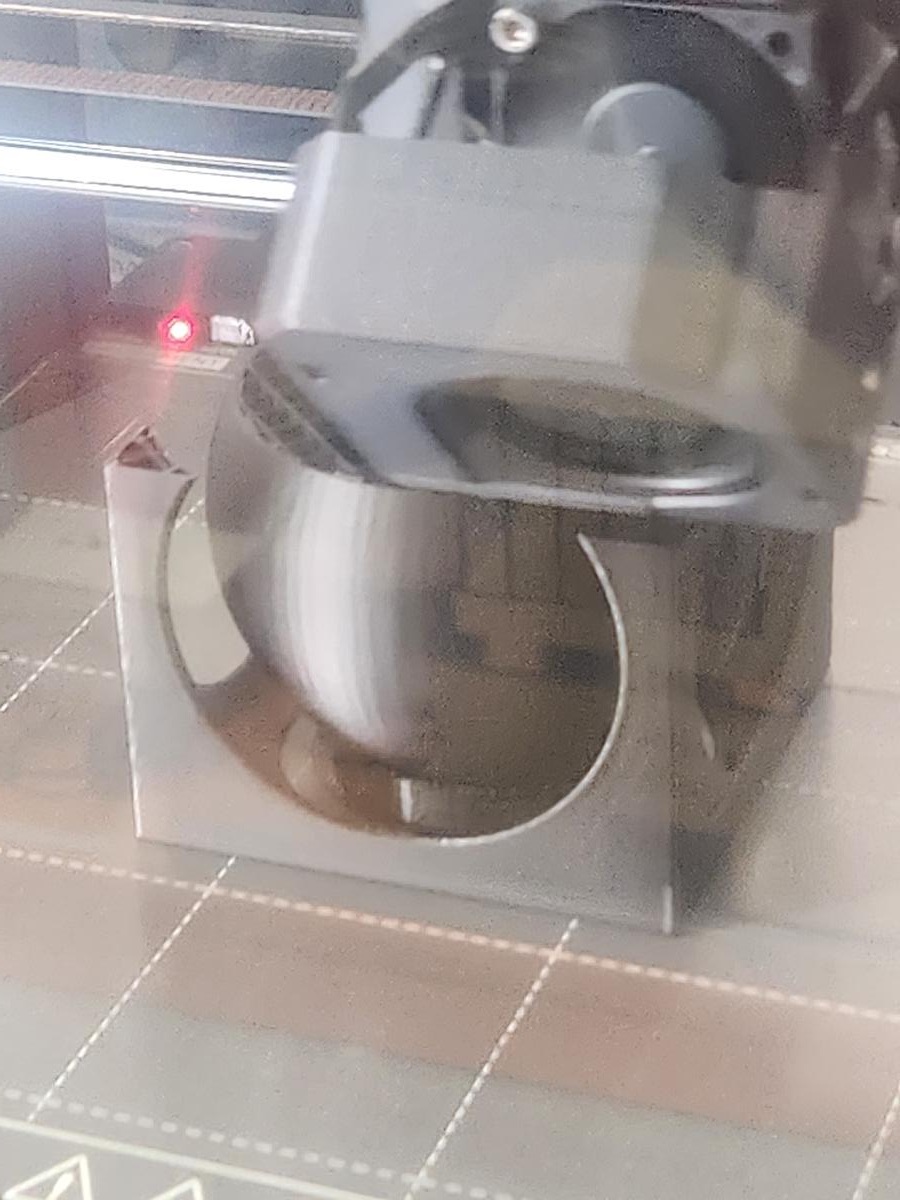
Since the sphere touches the bottom surface, manual support painting was used to stabilize the sphere during printing.
.jpg)
Why This Cannot Be Made Subtractively
This object cannot be manufactured using subtractive methods such as milling or drilling because:
- The sphere is fully enclosed inside the cube.
- There is no tool access to remove internal material.
- The internal sphere is a separate moving body.
- It requires additive layer-by-layer fabrication.
This demonstrates one of the key advantages of additive manufacturing: complex internal geometries and trapped assemblies can be printed in a single build.
Printing Status
Status: Work in Progress
The object has been sliced successfully and is ready for printing.
Final results, tolerance evaluation, and movement testing will be updated after printing.
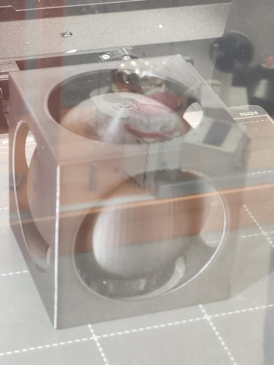
Scale Reduction Test (Factor ×0.25)
To further test the design limitations, I reduced the overall model dimensions by a factor of 4 and printed the smaller version. The purpose was to evaluate minimum feature size, tolerance, and printer capability at reduced scale.
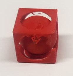
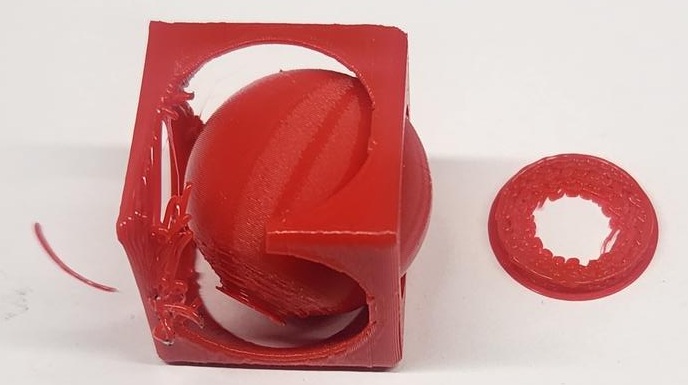
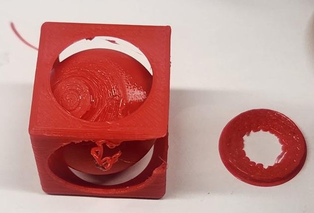
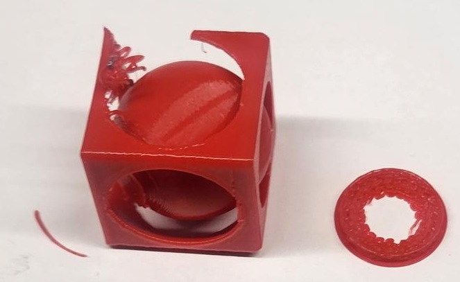
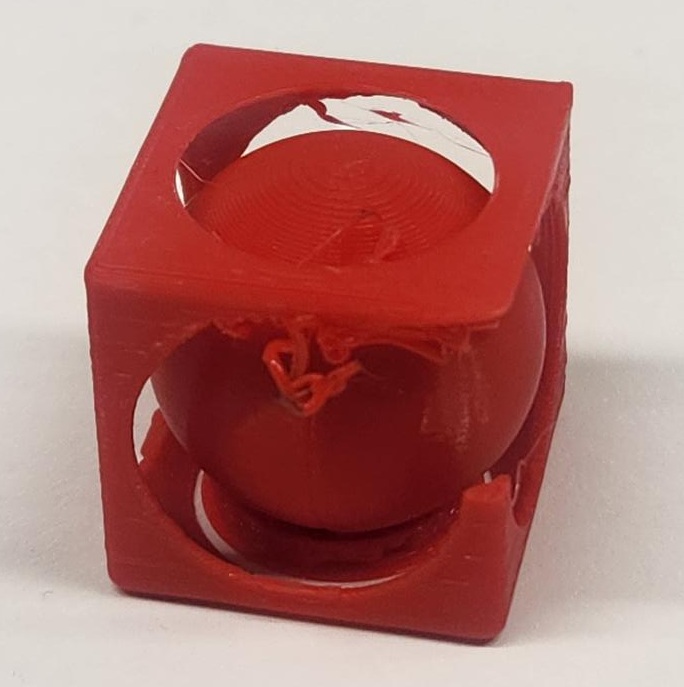
Observed Issues
- Support structures became difficult to remove at smaller scale.
- Internal sphere movement was restricted due to reduced clearance.
- Thin structural walls showed deformation and partial layer defects.
- Surface quality decreased, especially around circular cutouts.
- One things i am sure that these are not the issues of support.
At this reduced scale, the tolerance between the inner sphere and outer cube was no longer sufficient for smooth movement. This demonstrates how scaling directly impacts mechanical clearance, printer resolution limits, and structural stability.
Conclusion: While the original design works at full size, significant redesign of tolerances and wall thickness would be required for reliable miniaturization.
Learning Reflection
Through this exercise, I learned:
- How to use revolve-cut operations to create spherical cavities
- How to manage multiple bodies in Fusion 360
- How additive manufacturing enables trapped geometries
- Basic slicing and manual support generation in PrusaSlicer
This assignment strengthened my understanding of design-for-additive-manufacturing principles.
3D Scanning Process
Part 1 – Scanner Setup and Software Overview
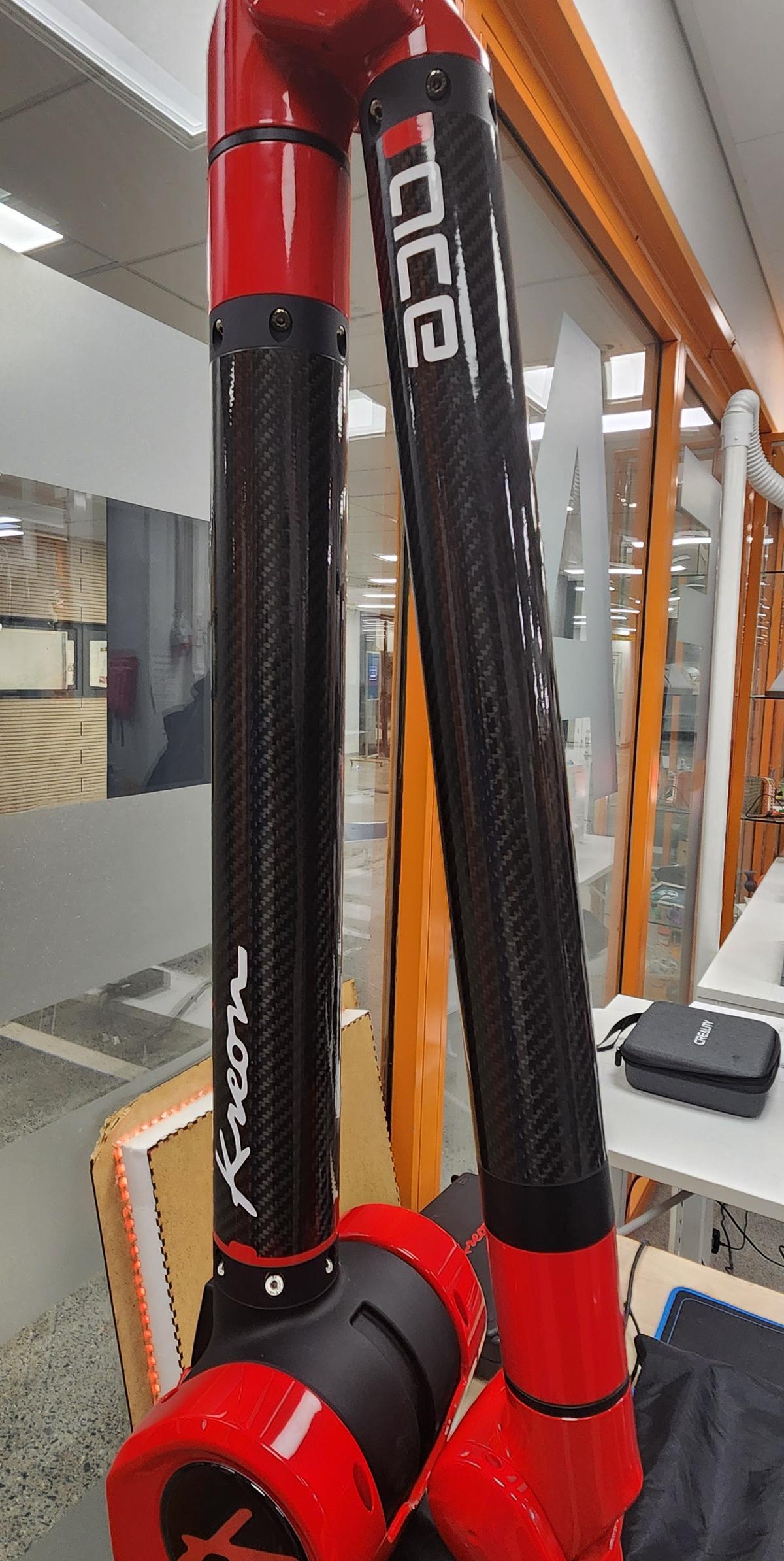
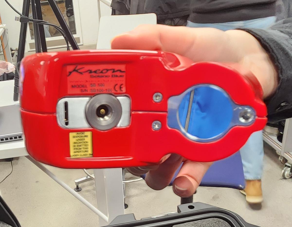
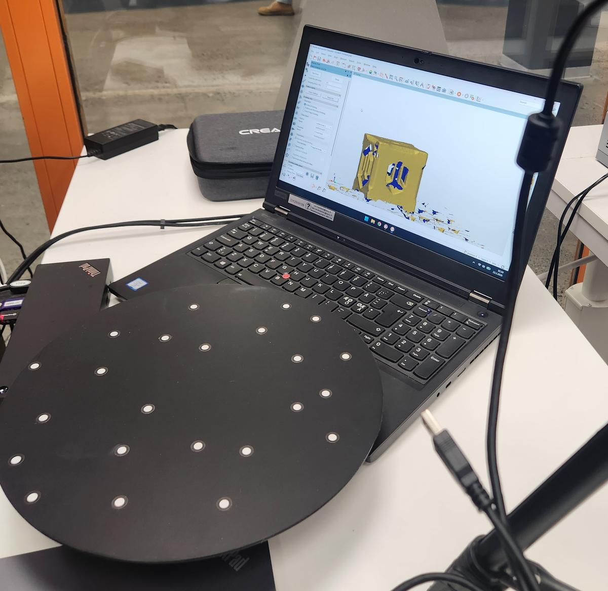
For the 3D scanning task, we used a structured-light 3D scanner setup connected to a laptop. The system included:
- 3D scanner mounted on a tripod
- Motorized turntable
- Calibration board
- Laptop with scanning software
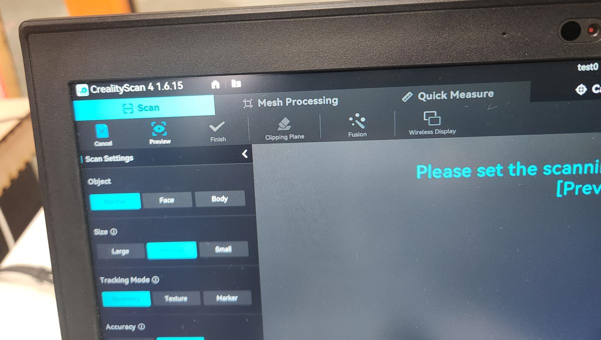
The scanner was connected via USB and controlled using Creality Scan software.
The scanning software interface allowed selecting:
- Object type (Normal / Face / Body)
- Object size (Small / Medium / Large)
- Tracking mode (Geometry / Texture / Marker)
- Accuracy settings
Software Issues Observed
During scanning, we experienced multiple software stability issues:
- The tracking frequently lost alignment
- The mesh appeared fragmented or floating
- The scanning process froze multiple times
- We had to restart the application several times
This showed that scanning quality heavily depends on lighting, object texture, and stable tracking.
Part 2 – Scanning Test Objects
Test Object 1 – Small Printed Cube
The first object we scanned was a small 3D printed cube. It was placed on the rotating platform to allow full 360° capture.
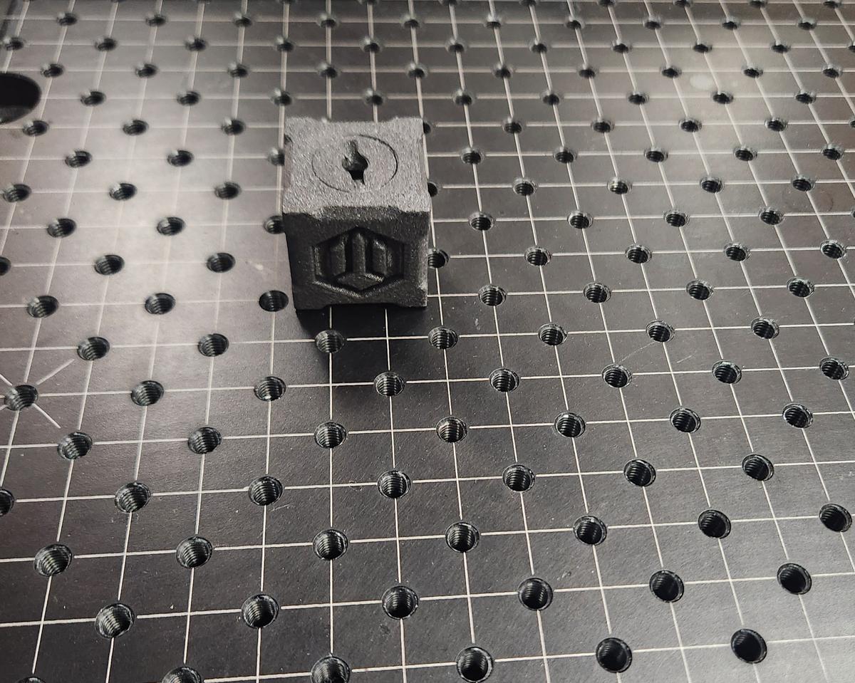
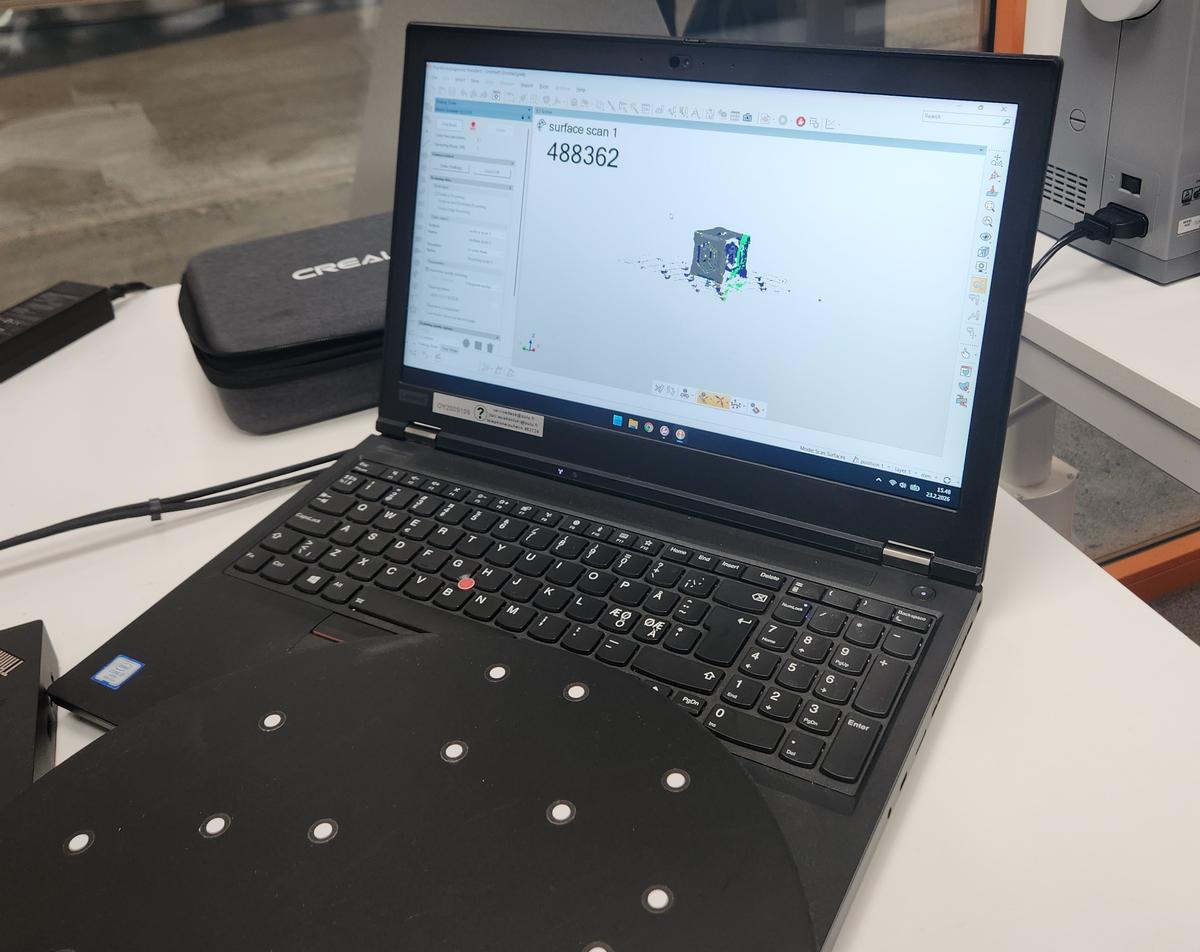
The scanner captured approximately 488,000 points during scanning. However, we observed:
- Noise around the base
- Incomplete capture on sharp edges
- Surface irregularities
The final mesh required post-processing for cleaning.
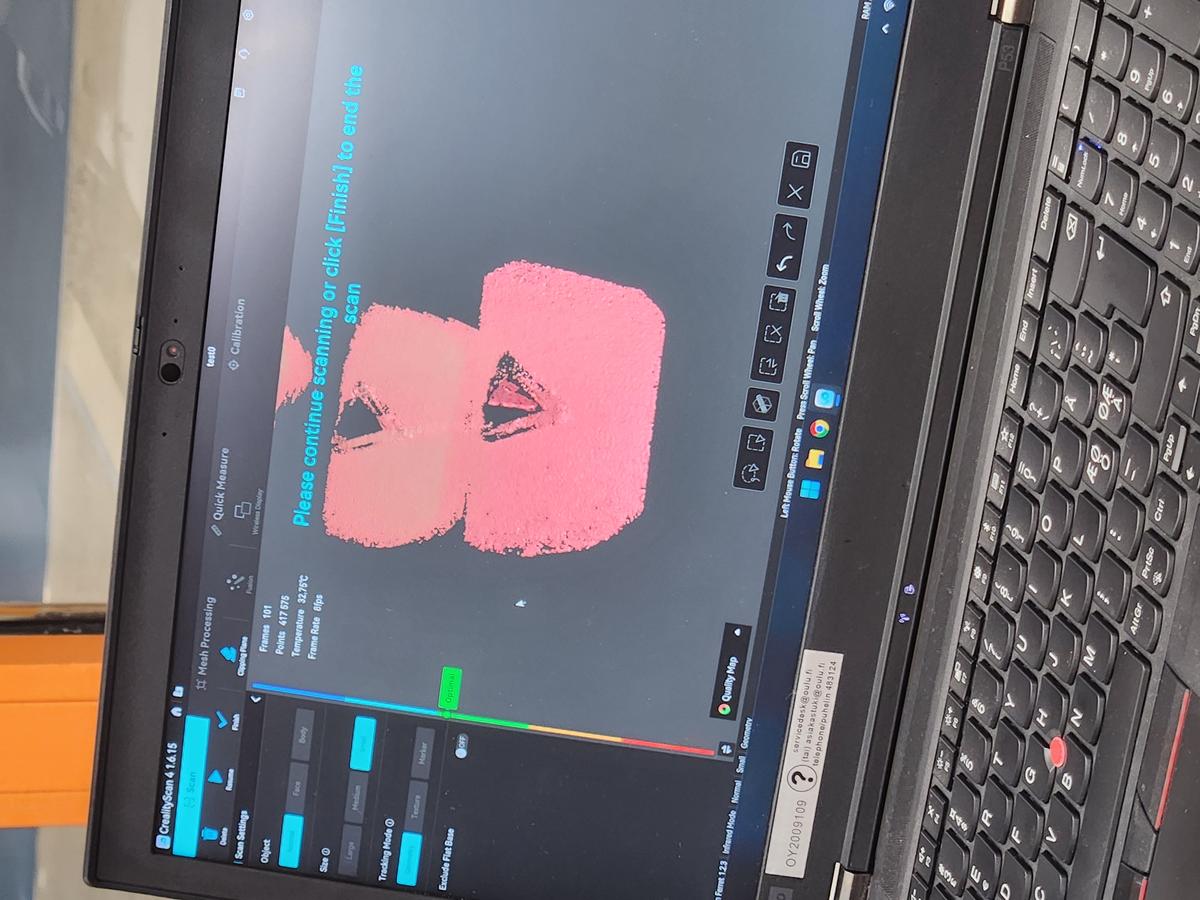
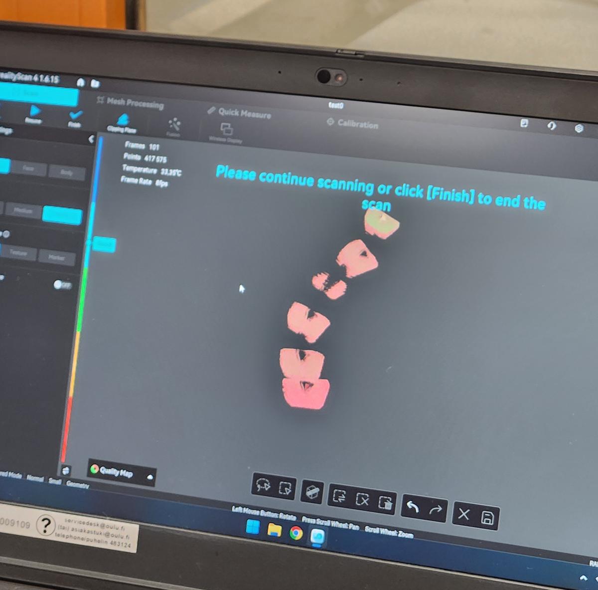
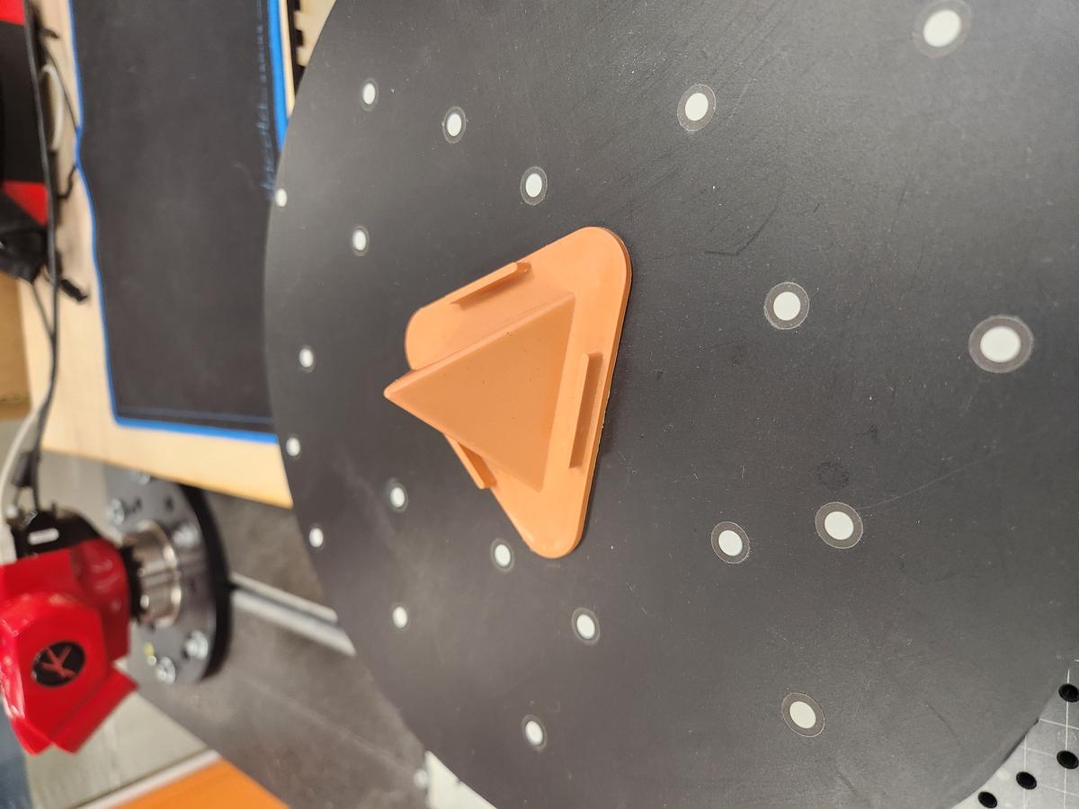
Test Object 2 – Triangular Pyramid Model
For the second experiment, I scanned a small orange triangular pyramid model mounted on the motorized turntable. The object consists of:
- A triangular pyramid top
- A rounded triangular base
- Flat surface regions with small geometric details
The scanner was configured in Normal mode with Small object size and Texture tracking enabled.
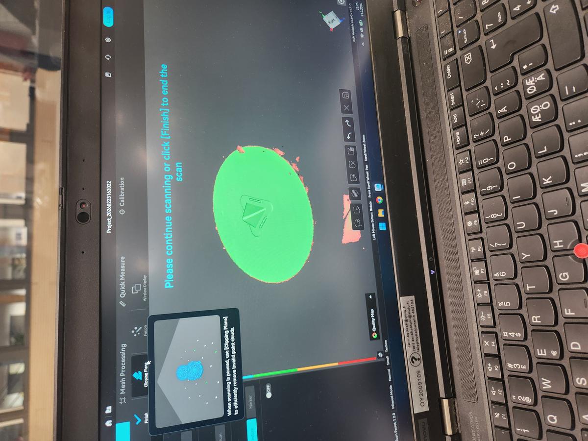
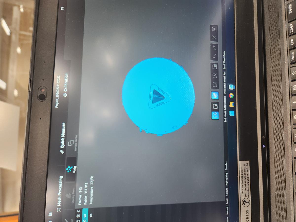
Scanning Stage
During scanning, the system captured approximately:
- 943 frames
- 112,312 points
- Frame rate around 12 fps
- Scanner temperature between 32°C – 38°C
The turntable allowed full 360° coverage. However, some unwanted point clouds were captured around the circular platform.
Mesh Processing
After completing the scan, I used the following mesh processing tools:
- Fusion to merge captured frames
- Resolution adjustment (~0.31 mm)
- Noise removal set to 50%
- Remove isolated parts (20%)
- Fill small holes (5 mm perimeter)
- Mesh smoothing (Medium)
The meshing process generated approximately 2.2 million triangles.
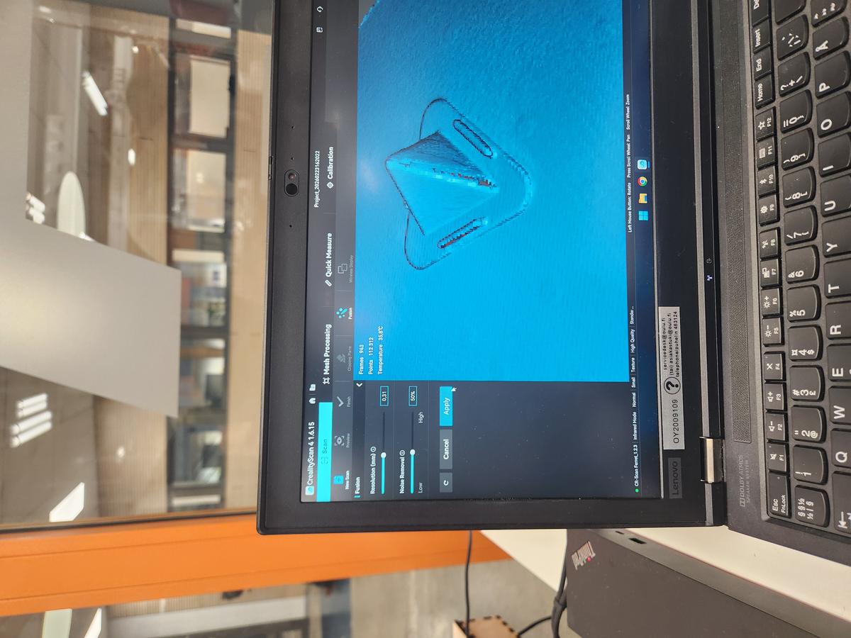
Challenges Observed
- Unwanted geometry captured from the turntable surface
- Noise around object boundaries
- Small mesh fragments around the circular base
- Minor surface roughness after fusion
The Clipping Plane tool was used to remove the turntable geometry and isolate only the scanned object.
Final Result
After cleaning and smoothing, the triangular pyramid model was successfully reconstructed. The final mesh preserved the pyramid edges and base geometry with acceptable surface quality.
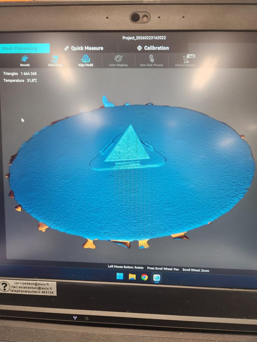
This demonstrated that shiny and reflective materials are difficult to scan accurately.
Part 3 – Mobile App Exploration
The mobile 3D scanning application was briefly explored to understand its interface and available scanning modes.
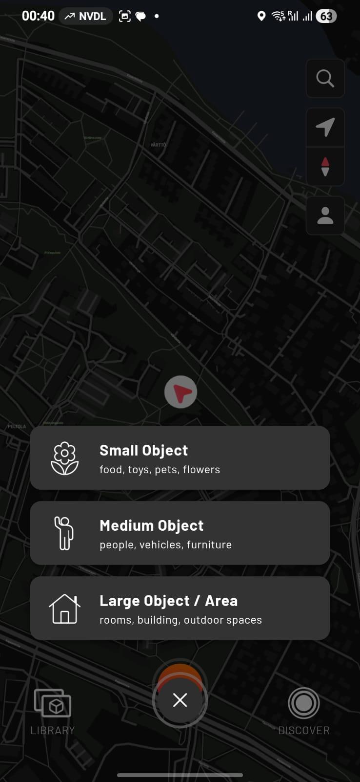
The application provides different scanning categories:
- Small Object – food, toys, pets, flowers
- Medium Object – people, vehicles, furniture
- Large Object / Area – rooms, buildings, outdoor spaces
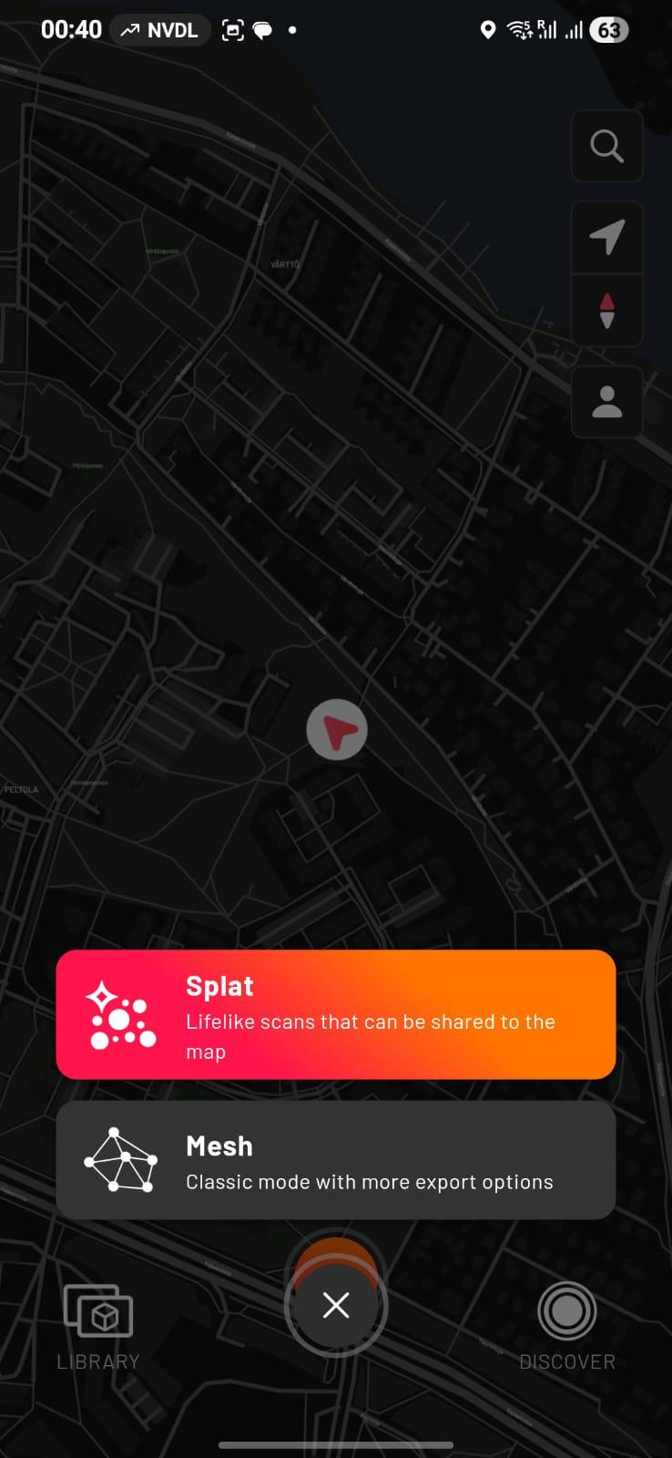
It also offers two main scanning modes:
- Splat Mode – Lifelike scans that can be shared to the map
- Mesh Mode – Classic mode with more export options
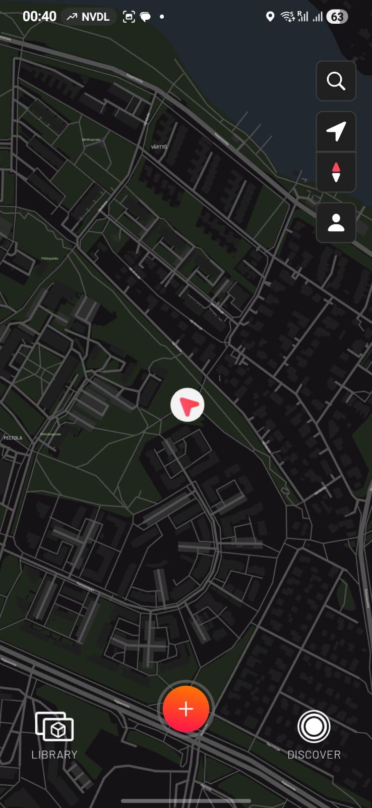
However, full mobile scanning was not performed. Initial testing showed that processing required significant time and device resources. Due to time limitations and performance constraints, the primary scanning workflow was completed using the desktop-based system.
Reflection on 3D Scanning
From this exercise, I learned:
- How structured-light scanners capture geometry
- The importance of stable tracking
- How surface properties affect scan quality
- Common issues such as noise and mesh fragmentation
- The difference between desktop and mobile scanning workflows
3D scanning is highly dependent on lighting conditions, object texture, and careful movement during capture.
4. Learning Outcome
- Understanding additive vs subtractive manufacturing
- Hands-on experience with slicing and 3D printing
- Understanding mesh structures and 3D scan processing
Assignment Overview
| Task | Status |
|---|---|
| 3D print designed object | Completed |
| Design object that cannot be made subtractively | Completed |
| 3D scan an object | Completed |
| Document process | Completed |