1. Objectives
- Learn parametric design principles using Autodesk Fusion 360
- Create a fully parameter-driven laser-cut model
- Apply constraints and circular pattern logic
- Design press-fit joints considering material thickness and kerf
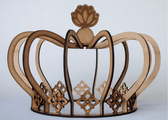
2. Inspiration & Concept
For this week's assignment, I decided to design a parametric crown structure inspired by laser-cut modular decorative models. The objective was not only to replicate a form but to understand how parametric constraints can control geometry.
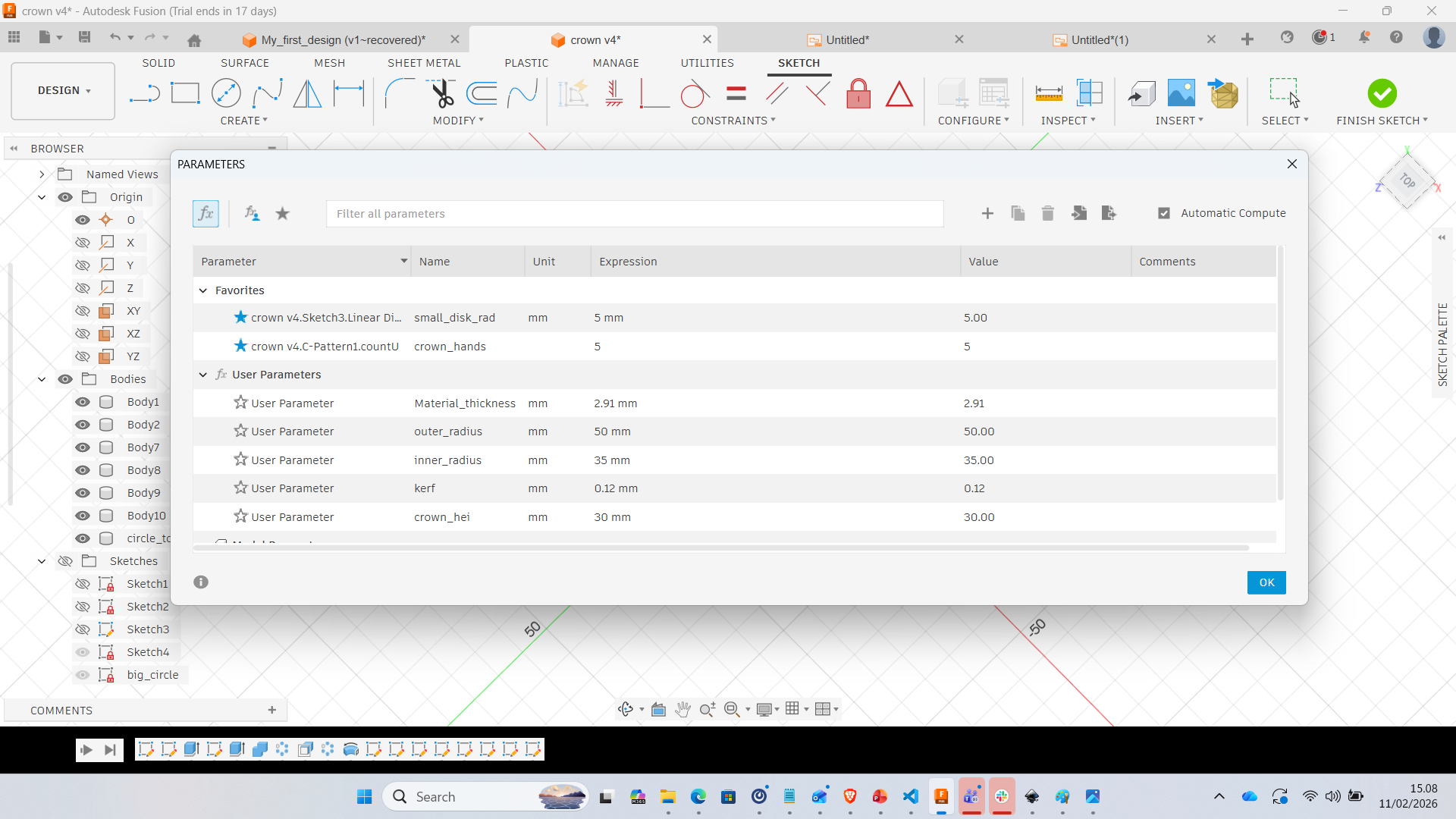
3. Parametric Setup
Before starting modeling, I defined user parameters to make the design fully adjustable. This ensures that the model can adapt to different materials and dimensions.
- Material_thickness = 2.91 mm
- Outer_radius = 50 mm
- Inner_radius = 35 mm
- Kerf = 0.12 mm
- Crown_height = 30 mm
- Number_of_segments = 5
4. Modeling Process in Fusion 360
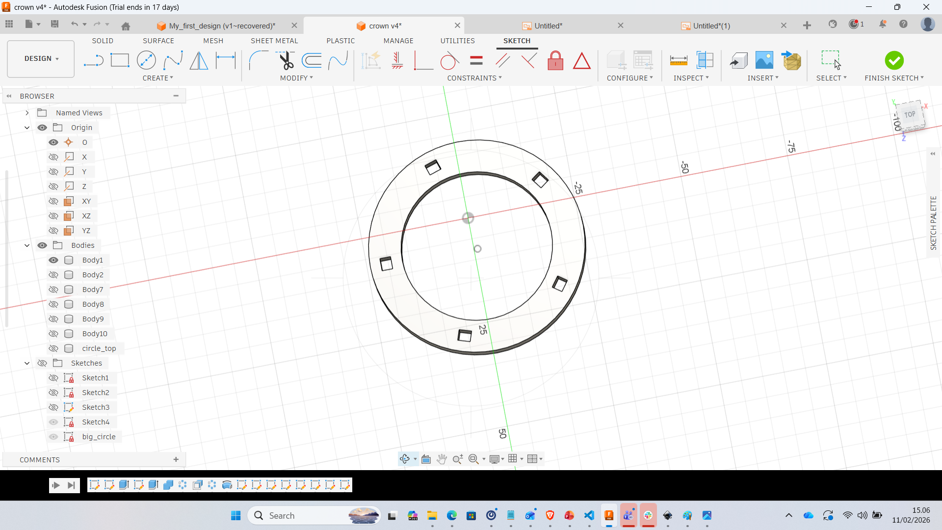
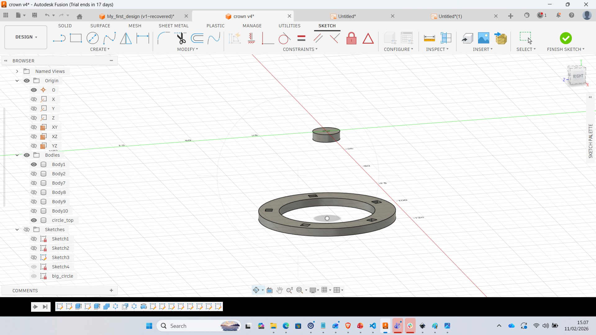
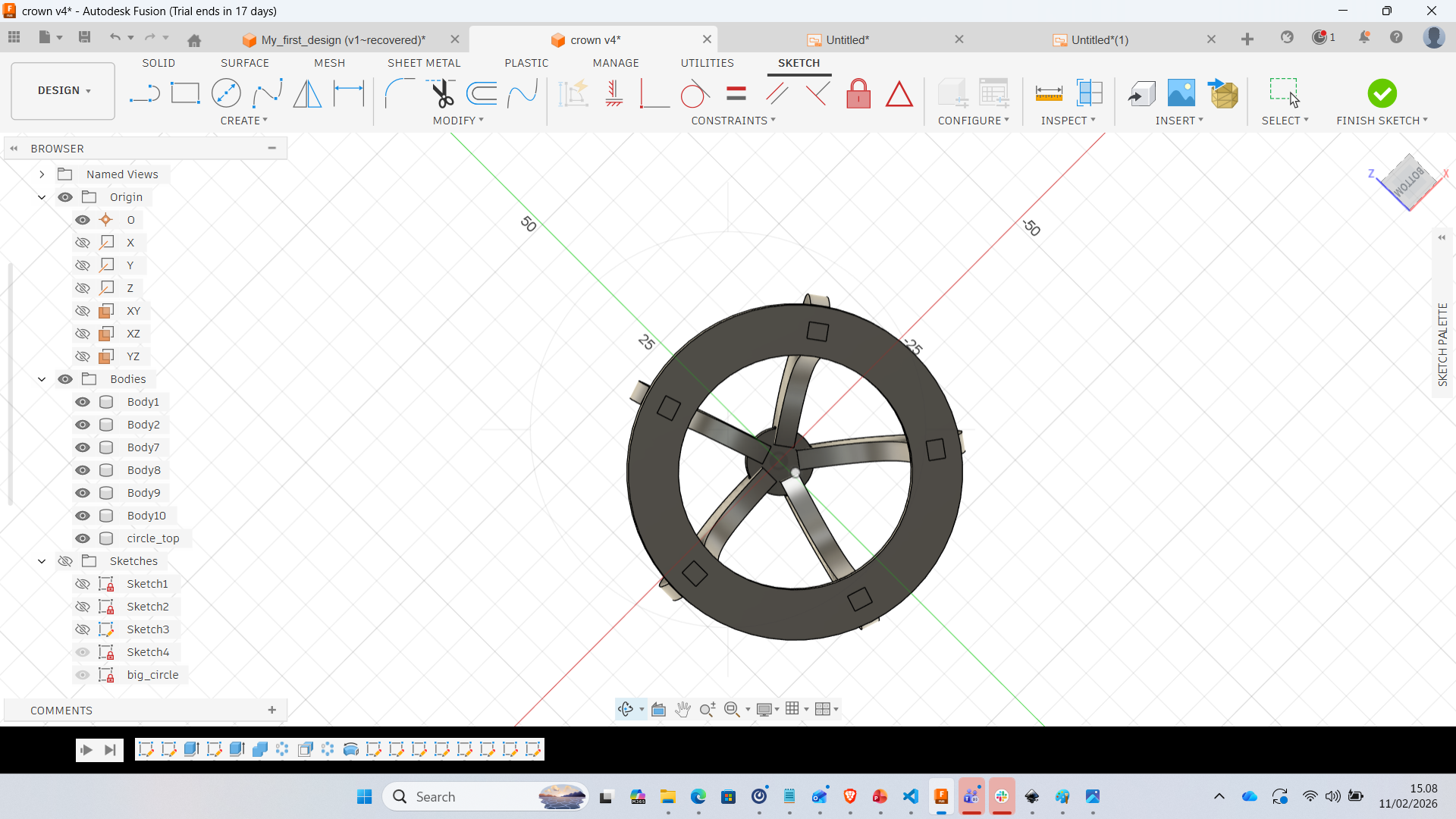
Step 1 – Base Ring Sketch
Two concentric circles were created using defined parameters. Square slots were placed evenly using circular pattern constraints.
Step 2 – Extrusion of Base
The ring was extruded according to the material thickness to create the base.
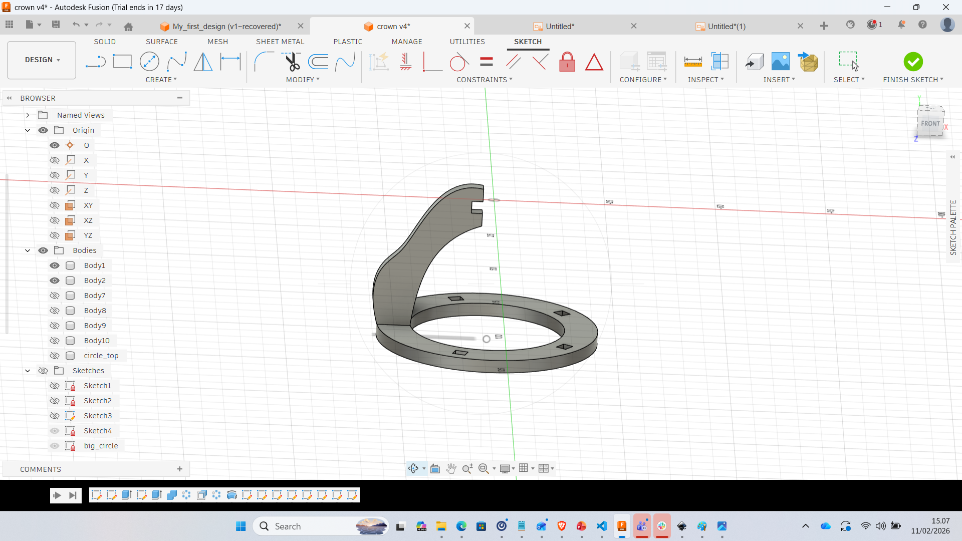
Step 3 – Creating Vertical Arm
A single curved segment was sketched and extruded to form one crown rib.
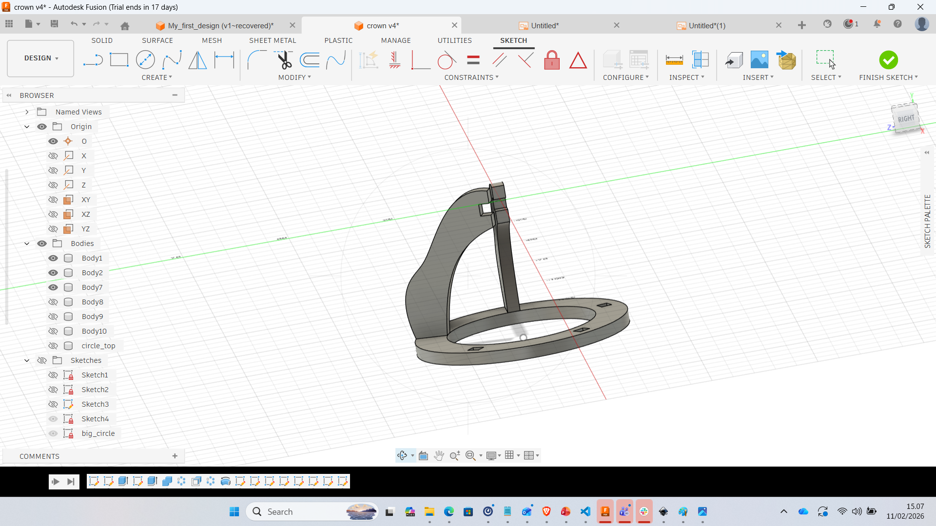
Step 4 – Assembly of Segment
The arm was aligned and positioned precisely to match slot geometry.
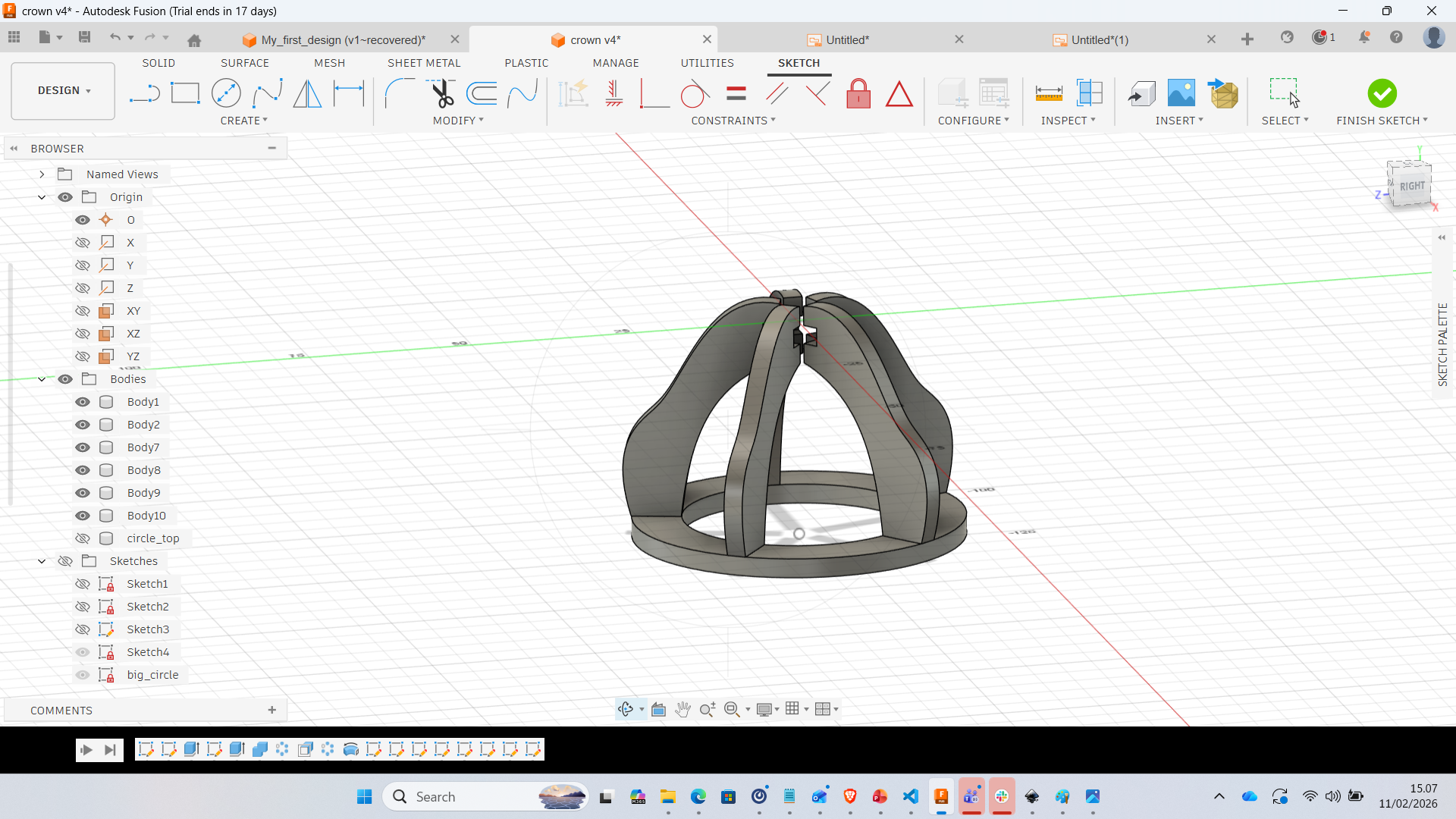
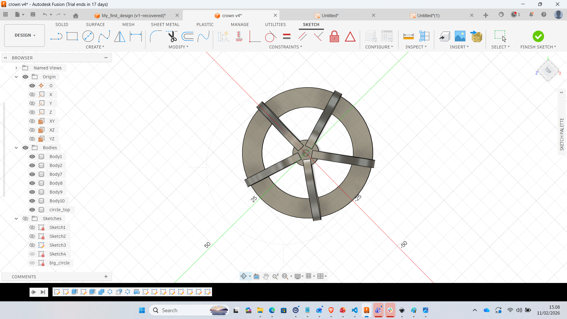
Step 5 – Circular Pattern
Using circular pattern, the single rib was replicated around the center axis. This ensures symmetry and structural balance.
Step 6 – Full Crown Structure
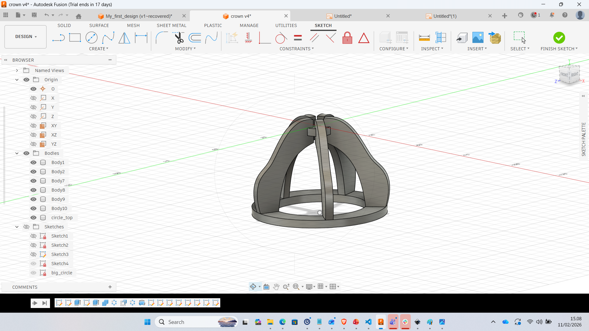
5. Design Considerations
- All slots were adjusted based on material thickness
- Kerf compensation was included
- Model is fully parametric and scalable
- Design prepared for laser cutting workflow
6. Reflection
This week significantly improved my understanding of parametric modeling. Instead of manually designing geometry, I focused on creating relationships between dimensions. By defining parameters first, the model becomes adaptable and reusable for different materials or sizes. Future improvements:
- Add decorative cut patterns
- Export 2D DXF for laser cutting
- Test physical press-fit tolerance
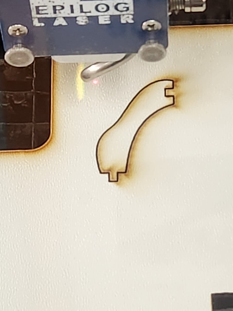
Fabrication Results – Laser Cutting & Assembly
After completing the 2D design in Inkscape and validating the geometry, the parts were exported in vector format and sent to the Epilog laser cutter. The material used was plywood, and kerf compensation was considered during the design phase to ensure proper press-fit assembly.
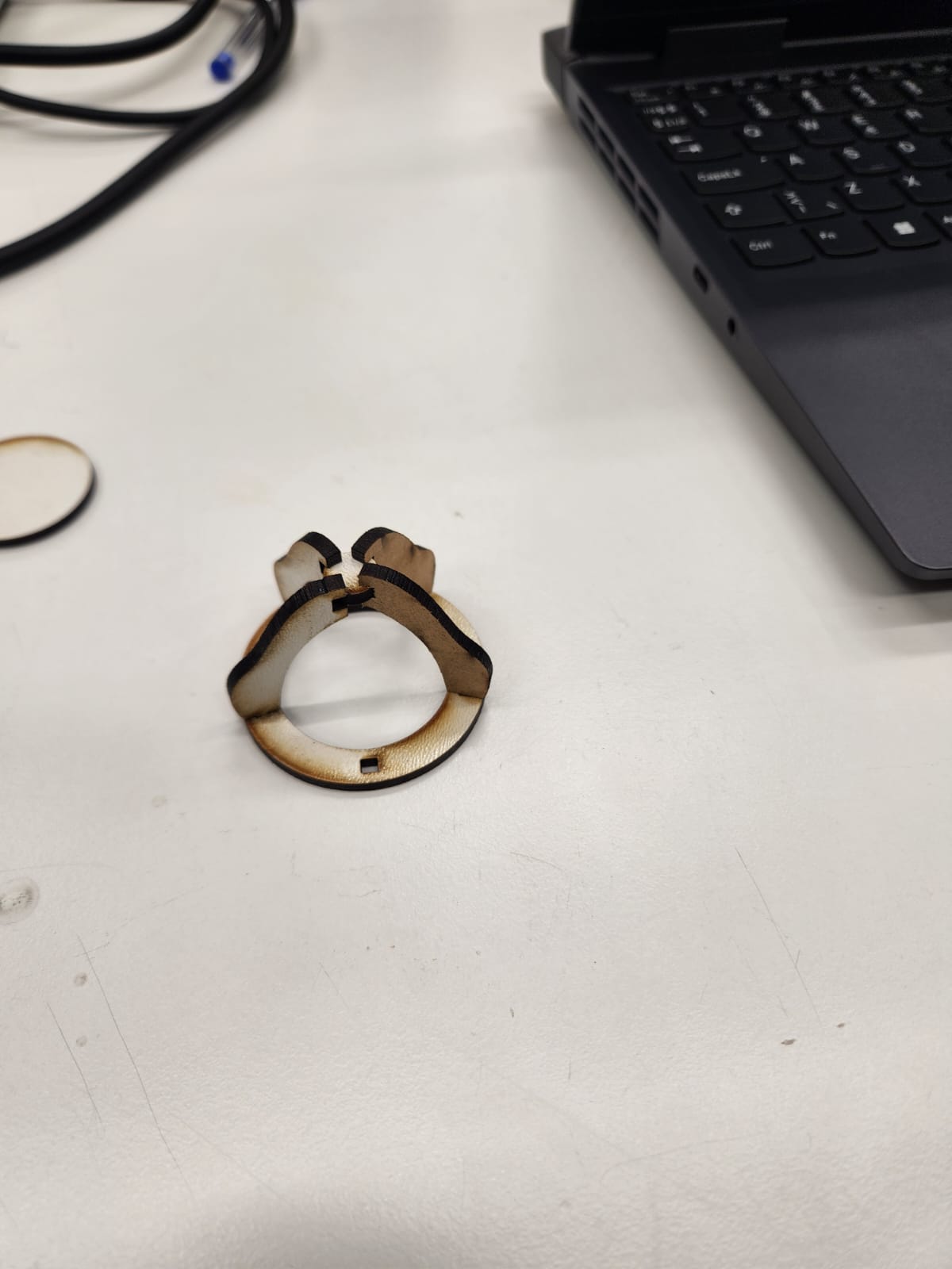
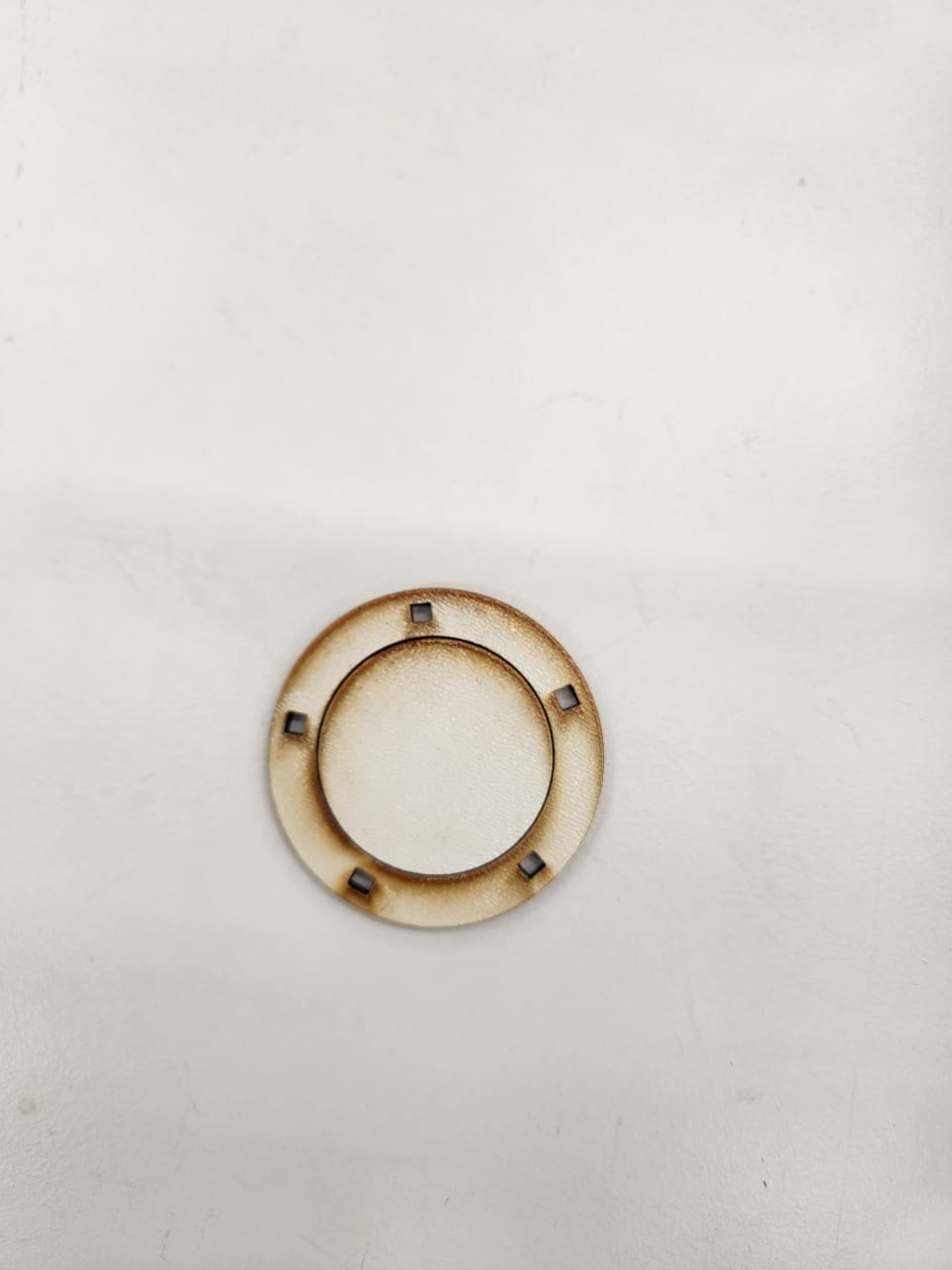
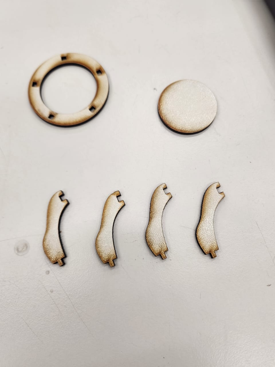
Individual Components After Cutting
The following images show the individual laser-cut parts. The ring structure and supporting curved legs were cut separately. Burn marks visible on the edges are a natural result of laser cutting on plywood material.
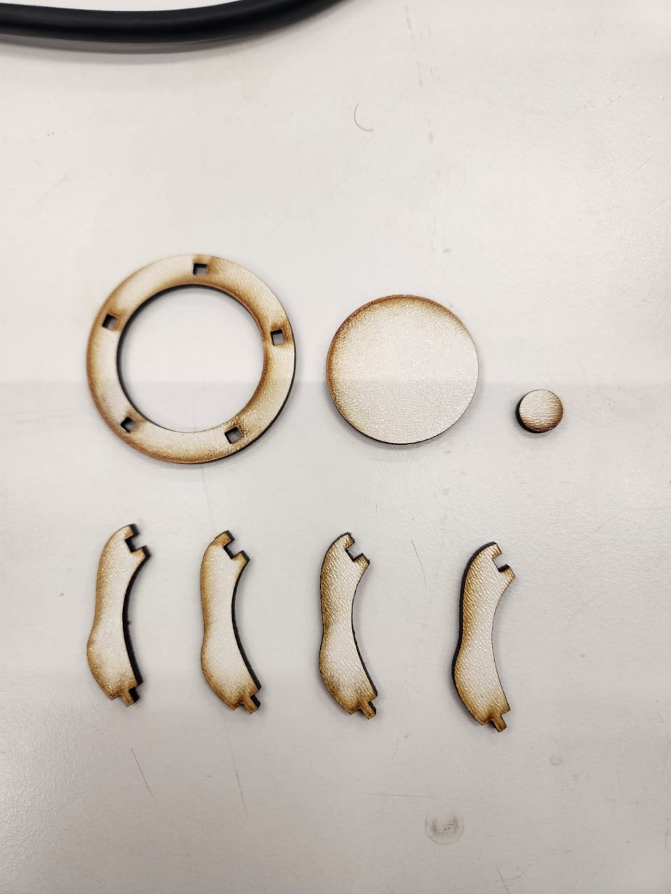
All Components Layout
Before assembly, all parts were organized and inspected to verify dimensional consistency and slot alignment. This step ensures that press-fit joints match the designed tolerances.
Assembly Process
The legs were inserted into the circular base through slot joints. The parametric design allowed the structure to hold firmly without glue. Minor adjustments were required to compensate for real-world material behavior and laser kerf variations.
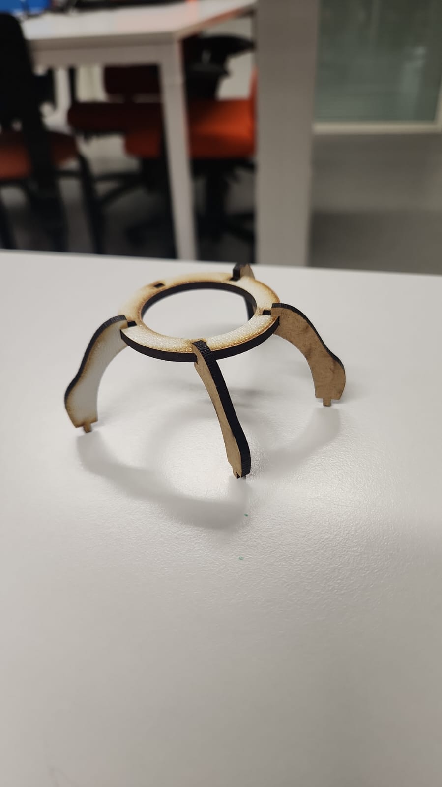
Final Structure
The final assembled prototype demonstrates a stable tripod-style support structure. The press-fit mechanism holds the components together without adhesives, showcasing the importance of precise parametric slot design in digital fabrication workflows.