Assignment Overview
The individual assignment focused on studying the RP2040 microcontroller datasheet, preparing and assembling the hardware platform, setting up the required programming environments, and developing firmware to interface with both input and output devices. The objective was to gain practical experience with embedded systems by understanding the microcontroller architecture and implementing a complete input–process–output workflow.
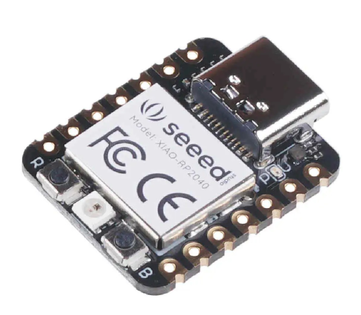
For this assignment, I used the Seeed Studio XIAO RP2040 as the primary microcontroller platform. The board is based on the Raspberry Pi RP2040 microcontroller and provides a compact development environment with GPIO, ADC, PWM, I²C, SPI, and UART interfaces. Throughout the assignment, the XIAO RP2040 was used to communicate with external peripherals including capacitive touch pads, an SSD1306 OLED display, and the onboard NeoPixel RGB LED.
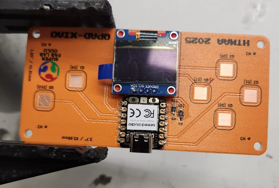
For the hardware platform, I assembled a QPAD (Quick Prototyping and Development) board, originally developed within the Fab Academy community to simplify experimentation with the XIAO family of microcontrollers. The QPAD design provides convenient access to GPIO pins, touch pads, and peripheral connections, allowing rapid prototyping without the need to design a custom PCB for each experiment.
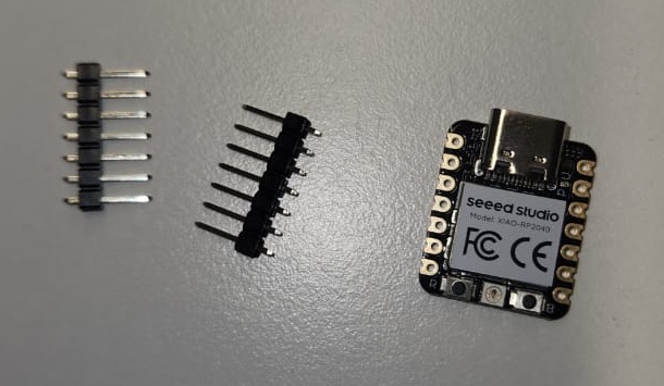
The QPAD board used in this assignment was fabricated by fellow Fab Academy local instructor Ivan and Gleb. Hardware preparation involved soldering the XIAO RP2040, the SSD1306 OLED display, and two resistors onto the board. Pin headers were aligned and soldered using a soldering mask to ensure accurate positioning and reliable electrical connections. The assembly process was straightforward and provided a stable platform for subsequent programming and testing activities.
The original QPAD design and documentation are available at: QPAD-XIAO Project Repository . Additional background information about the Ivan and Gleb can be found in the Fab Academy documentation: Fab Academy: Iván Sánchez Milara . Fab Academy: Gleb Bulygin .
Main Requirements
- Browse and study a microcontroller datasheet
- Program a microcontroller development board
- Test input and output behavior
- Document the programming and debugging workflow
My Focus
- Seeed Studio XIAO RP2040
- Arduino IDE, Thonny, and MicroBlocks
- OLED display output using I2C
- Touch input with NeoPixel and OLED feedback
Seeed Studio XIAO RP2040
For this assignment, the main microcontroller platform used was the Seeed Studio XIAO RP2040. The board is based on the Raspberry Pi RP2040 dual-core ARM Cortex-M0+ microcontroller operating at up to 133 MHz. Despite its extremely compact size, the board provides multiple digital GPIO pins, analog inputs, PWM support, UART, SPI, and I2C communication interfaces, making it highly suitable for embedded systems prototyping and rapid hardware experimentation.
One of the key reasons for selecting this board was its compact form factor, integrated USB-C programming interface, and compatibility with multiple development environments including:
- Arduino IDE
- MicroPython
- C/C++ SDK
- Zephyr RTOS
During this assignment, the XIAO RP2040 was interfaced with an SSD1306 OLED display over the I2C communication bus. Additionally, the onboard RGB NeoPixel LED and external capacitive touch pads available on the fabricated PCB were used to demonstrate both input and output interaction within the embedded system.
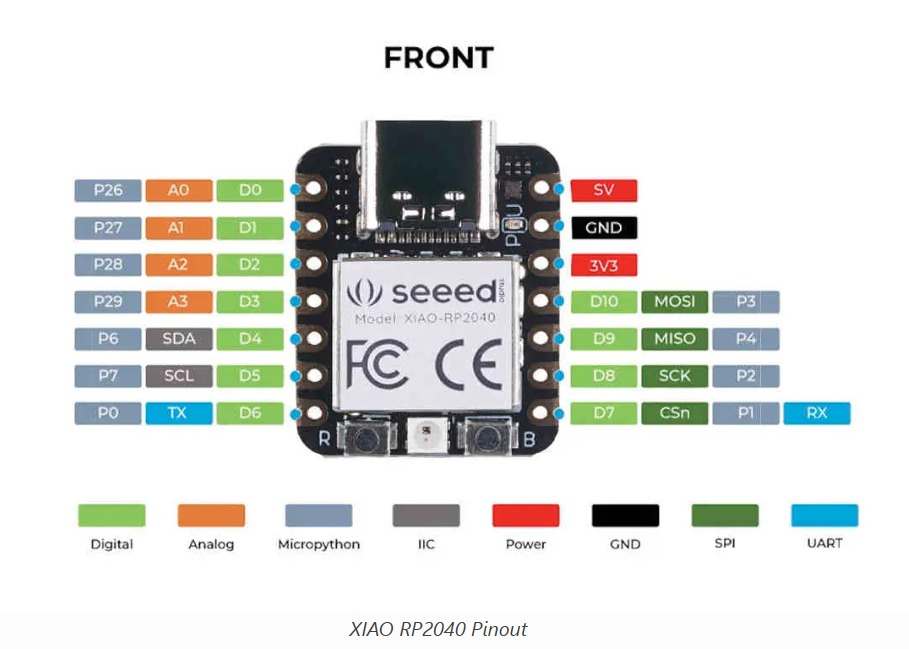
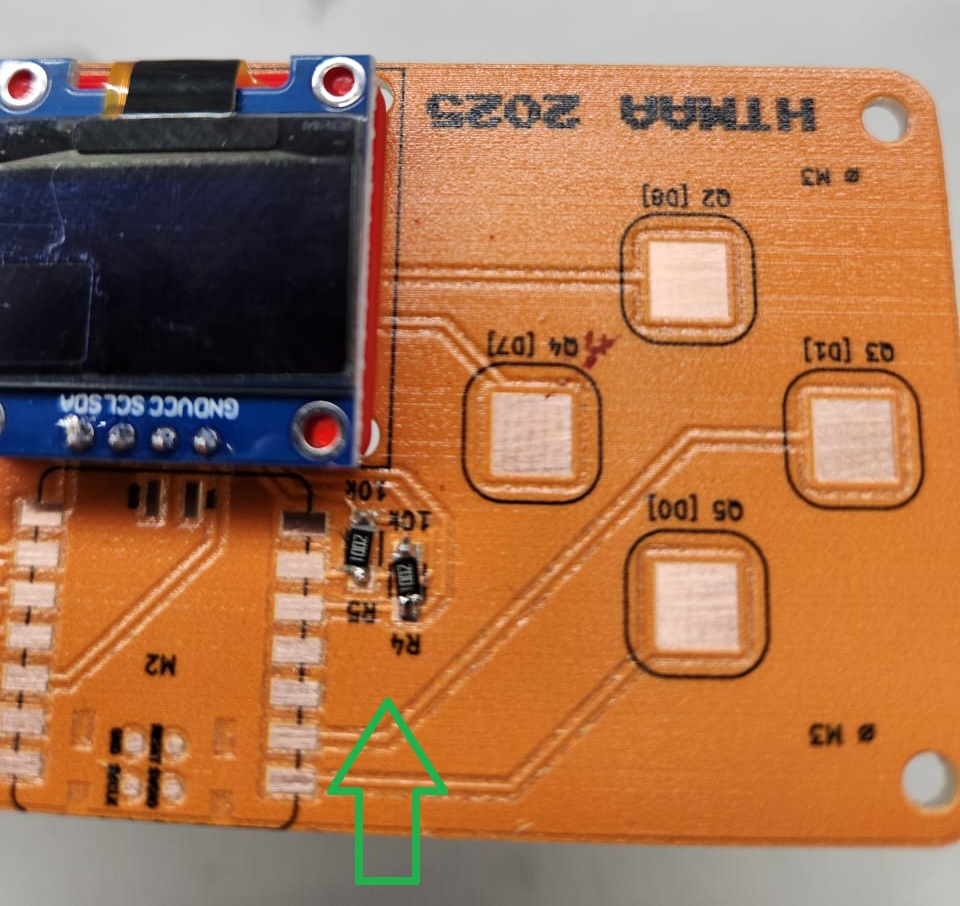
The RP2040 provides two programmable I2C interfaces. In this assignment, GPIO6 (SDA) and GPIO7 (SCL) were configured for communication with the OLED display. The fabricated board also routed several GPIO pins to large copper touch pads, enabling simple capacitive-touch interaction experiments.
The onboard RGB LED available on the XIAO RP2040 was later utilized to create a simplified traffic-light demonstration system. Different LED colors were triggered based on touch-pad interaction, while the OLED display simultaneously provided visual feedback and system status information.
The RP2040 microcontroller contains a dual-core Cortex-M0+ architecture, programmable I/O (PIO) subsystem, hardware timers, watchdog timer, DMA controller, and multiple communication peripherals. These features make the device highly attractive for real-time embedded systems, low-level hardware interfacing, and educational prototyping applications.
Additional hardware documentation and Zephyr RTOS support information for the XIAO RP2040 can be found here:
RP2040 Datasheet Exploration
I explored the RP2040 datasheet to understand the architecture and hardware capabilities of the board. The datasheet includes information about GPIO, timers, communication protocols, memory organization, power management, and embedded peripherals.
- Dual-core ARM Cortex-M0+ processor
- Programmable GPIO pins
- ADC and PWM functionality
- UART, SPI, and I2C communication support
- USB interface for programming and communication
- Watchdog timer for reliability and fault recovery
Watchdog Timer Case Study
I found the watchdog timer interesting because it shows how embedded systems can recover automatically from software failures. If a program crashes or becomes unresponsive, the watchdog can reset the microcontroller and restore operation.
A well-known example is the Mars Pathfinder mission in 1997. The spacecraft experienced system resets due to a priority inversion problem. The watchdog timer detected that a critical task was not running correctly and reset the system. Although the resets interrupted operations, they prevented the system from becoming permanently unresponsive.
Note: Additional information about the Mars Pathfinder incident: Read the article
Soldering and Board Assembly
Before programming, I practiced soldering and prepared the hardware setup. This was important because embedded programming depends not only on code, but also on reliable electrical connections and properly assembled boards.
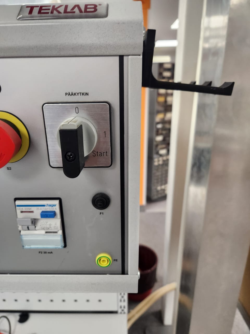
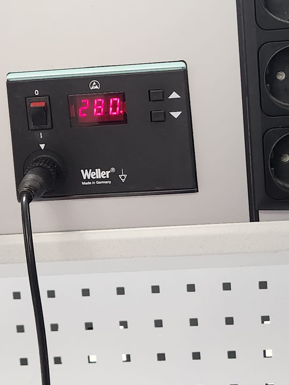
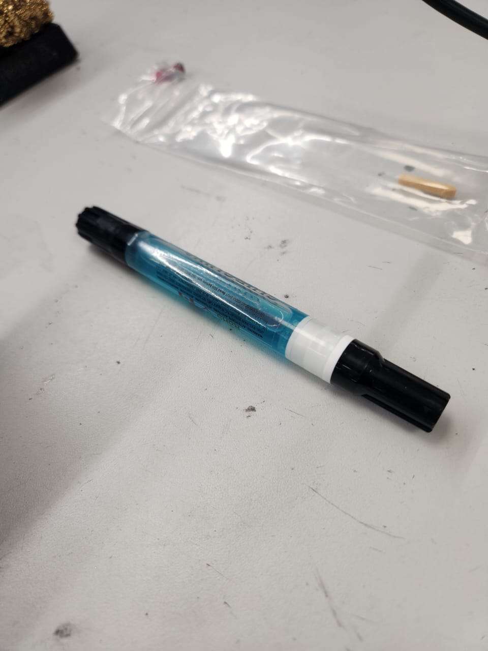
Soldering Workstation
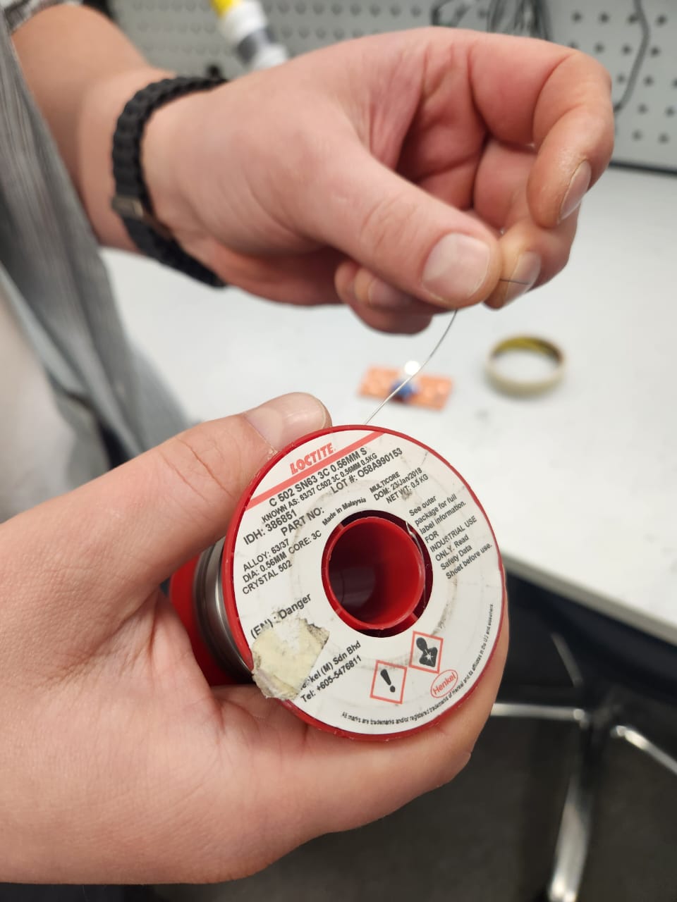
PCB Soldering Practice
I soldered small components onto a pre-fabricated PCB to understand component placement, solder joint formation, and surface-mount handling.
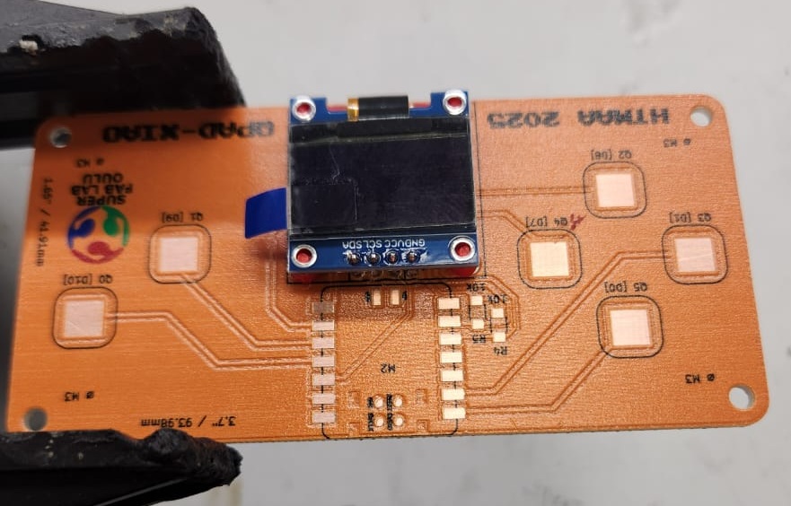
XIAO RP2040 Assembly
After soldering practice, I assembled the XIAO RP2040 module onto the demonstration PCB using header pins. The board was visually inspected after soldering to check alignment and solder joint quality.
Programming Environment Setup
Arduino IDE Setup
Follow the setup instructions here: Seeed Studio XIAO RP2040 Arduino Guide
I used Arduino IDE as the main programming environment. After installing Arduino IDE, I added the RP2040 board support package using the Additional Boards Manager URL.
https://github.com/earlephilhower/arduino-pico/releases/download/global/package_rp2040_index.json
.png)
.png)
.png)
Thonny and MicroPython
Follow the setup instructions here: Seeed Studio XIAO RP2040 MicroPython Guide
I also explored Thonny IDE with MicroPython. Thonny provides direct access to the MicroPython shell and is useful for quick testing.
.png)
.png)
MicroBlocks
Explore MicroBlocks here: microblocks.fun
MicroBlocks was tested as a visual programming environment. It allowed quick testing of the XIAO RP2040 board and NeoPixel output.
.png)
.png)
Basic Output Tests
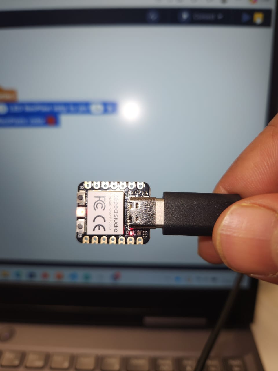
The first experiment was a simple LED blink program. This verified the programming environment, USB communication, firmware upload process, and basic GPIO control.
#define PIN_RED 17
#define PIN_GREEN 16
#define PIN_BLUE 25

void setup() {
  pinMode(PIN_RED, OUTPUT);
  pinMode(PIN_GREEN, OUTPUT);
  pinMode(PIN_BLUE, OUTPUT);

  digitalWrite(PIN_RED, HIGH);
  digitalWrite(PIN_GREEN, HIGH);
  digitalWrite(PIN_BLUE, HIGH);
}

void loop() {
  digitalWrite(PIN_GREEN, LOW);
  delay(500);
  digitalWrite(PIN_GREEN, HIGH);
  delay(500);
}
.png)
MicroPython GPIO Test
from machine import Pin
import time

led = Pin(25, Pin.OUT)

while True:
    led.on()
    time.sleep(1)
    led.off()
    time.sleep(1)
OLED Programming and Debugging
After assembling the XIAO RP2040 board and OLED display module, I tested communication between the microcontroller and the SSD1306 OLED display using I2C. The SDA and SCL lines were connected to GPIO6 and GPIO7.
#include <Wire.h>
#include <Adafruit_GFX.h>
#include <Adafruit_SSD1306.h>

#define SCREEN_WIDTH 128
#define SCREEN_HEIGHT 64

#define SDA_PIN 6
#define SCL_PIN 7

Adafruit_SSD1306 display(SCREEN_WIDTH, SCREEN_HEIGHT, &Wire, -1);

void setup() {
  Serial.begin(115200);

  Wire.setSDA(SDA_PIN);
  Wire.setSCL(SCL_PIN);
  Wire.begin();

  if (!display.begin(SSD1306_SWITCHCAPVCC, 0x3C)) {
    Serial.println("SSD1306 allocation failed");
    while (true);
  }

  display.clearDisplay();
  display.display();
  Serial.println("OLED Initialized Successfully");
}

void loop() {
  for (int y = -24; y < 64; y++) {
    display.clearDisplay();
    display.setTextSize(1);
    display.setTextColor(SSD1306_WHITE);

    display.setCursor(0, y);
    display.println("FabAcademy2026!");

    display.setCursor(0, y + 10);
    display.println("FabLab Oulu!");

    display.setCursor(0, y + 20);
    display.println("DINESH");

    display.display();
    delay(50);
  }
}
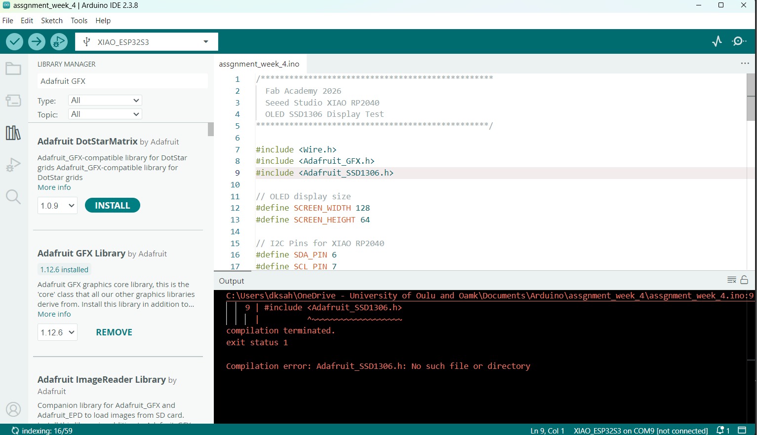
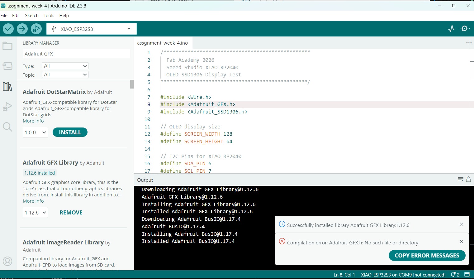
During compilation, I encountered missing library errors for
Adafruit_GFX.h and Adafruit_SSD1306.h.
I fixed this by installing Adafruit SSD1306, Adafruit GFX Library,
and Adafruit BusIO from the Arduino Library Manager.
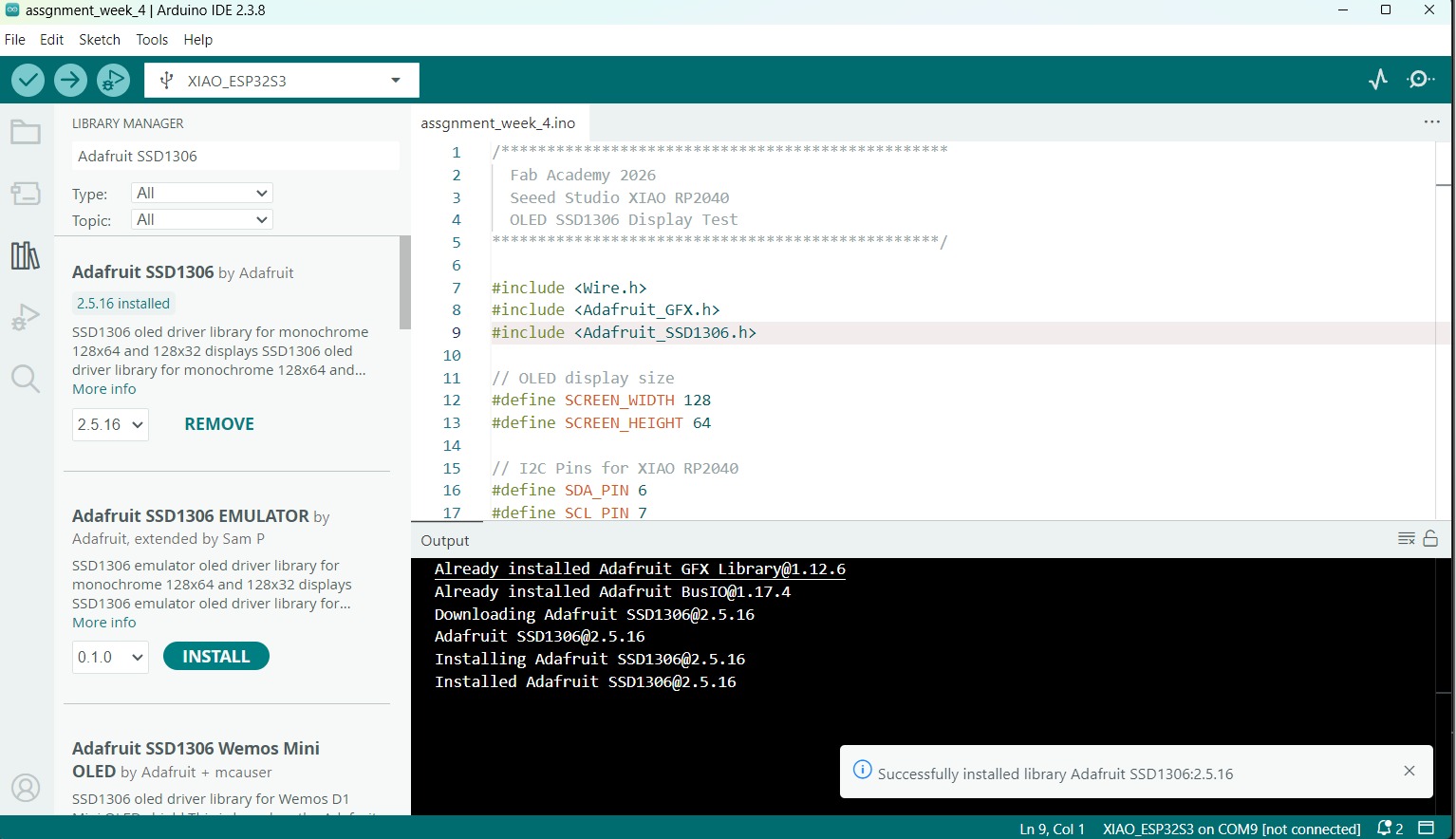
Successfully established I2C communication between the XIAO RP2040 and SSD1306 OLED display using Arduino IDE.
Touch Input and OLED Output Demonstration
As the final part of the individual assignment, I developed a simple interactive system using the XIAO RP2040, touch pads, onboard NeoPixel RGB LEDs, and an SSD1306 OLED display.
- Read input from capacitive touch pads
- Display status on the OLED screen
- Provide visual feedback using the RGB LED
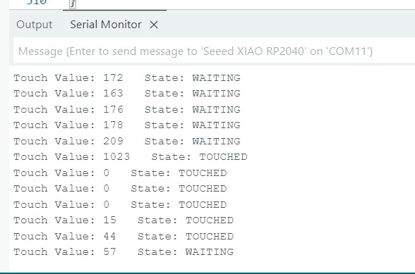
- Monitor values through the Arduino Serial Monitor
Initial Challenges
Final Program
The final program integrates three peripherals simultaneously:
- Capacitive Touch Pad connected to A0 for user input.
- SSD1306 OLED Display connected through I²C for status messages.
- NeoPixel RGB LED for immediate visual feedback.
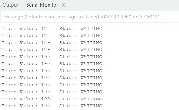
The software continuously monitors the analog value of the touch pad using
analogRead(). Experimental testing showed that touching the pad
often produced extreme values close to 0 or 1023, while untouched values
remained within a narrower range. Therefore, threshold-based detection was
implemented. When a touch is detected, the OLED displays
TOUCHED and the RGB LED turns green. Otherwise, the OLED
displays WAITING and the RGB LED remains red.
/************************************************* Fab Academy 2026 XIAO RP2040 Touch Input + OLED Output *************************************************/ #include#include #include #include #define SCREEN_WIDTH 128 #define SCREEN_HEIGHT 64 #define SDA_PIN 6 #define SCL_PIN 7 Adafruit_SSD1306 display(SCREEN_WIDTH, SCREEN_HEIGHT, &Wire, -1); #define LED_PIN 11 #define LED_COUNT 1 Adafruit_NeoPixel pixel(LED_COUNT, LED_PIN, NEO_GRB + NEO_KHZ800); // Q5 pad connected to A0 / D0 #define TOUCH_PIN A0 String lastState = ""; void setup() { Serial.begin(115200); delay(2000); Serial.println("System Started"); Wire.setSDA(SDA_PIN); Wire.setSCL(SCL_PIN); Wire.begin(); if (!display.begin(SSD1306_SWITCHCAPVCC, 0x3C)) { Serial.println("OLED Failed"); while (true); } pixel.begin(); pixel.clear(); pixel.show(); showWaiting(); Serial.println("Setup Complete"); } void loop() { int touchValue = analogRead(TOUCH_PIN); bool isTouched = (touchValue < 50 || touchValue > 800); Serial.print("Touch Value: "); Serial.print(touchValue); Serial.print(" State: "); if (isTouched) { ``` Serial.println("TOUCHED"); if (lastState != "TOUCHED") { showTouched(); lastState = "TOUCHED"; } ``` } else { ``` Serial.println("WAITING"); if (lastState != "WAITING") { showWaiting(); lastState = "WAITING"; } ``` } delay(300); } void showWaiting() { pixel.setPixelColor(0, pixel.Color(255, 0, 0)); pixel.show(); display.clearDisplay(); display.setTextSize(1); display.setTextColor(SSD1306_WHITE); display.setCursor(0, 0); display.println("Fab Academy 2026"); display.setTextSize(2); display.setCursor(0, 25); display.println("WAITING"); display.display(); } void showTouched() { pixel.setPixelColor(0, pixel.Color(0, 255, 0)); pixel.show(); display.clearDisplay(); display.setTextSize(1); display.setTextColor(SSD1306_WHITE); display.setCursor(0, 0); display.println("Fab Academy 2026"); display.setTextSize(2); display.setCursor(0, 25); display.println("TOUCHED"); display.display(); }
Code Explanation
The program begins by initializing the I²C interface, OLED display, NeoPixel LED, and Serial Monitor. During each execution of the main loop, the analog value from the touch pad is sampled and compared against experimentally determined thresholds. Values below 50 or above 800 are interpreted as a valid touch event.
To avoid unnecessary screen refreshes, a state variable
(lastState) is used. The OLED display and RGB LED are only
updated when the system transitions between the WAITING and
TOUCHED states. This significantly improves stability and
reduces flickering caused by noisy sensor readings.
The demonstration successfully combines sensor input, serial debugging, OLED display output, and RGB LED control in a single embedded application, illustrating the complete input–process–output workflow of the XIAO RP2040.
The touch pads produced unstable analog values. Without touching the pad, readings were around 130-190. When touched, readings moved toward extreme values near 0 or 1023. Because of this behavior, the display and RGB LED initially switched states too quickly.
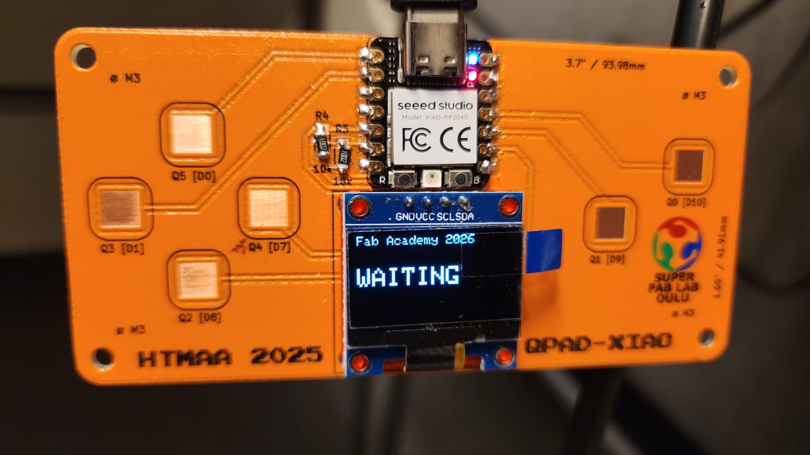
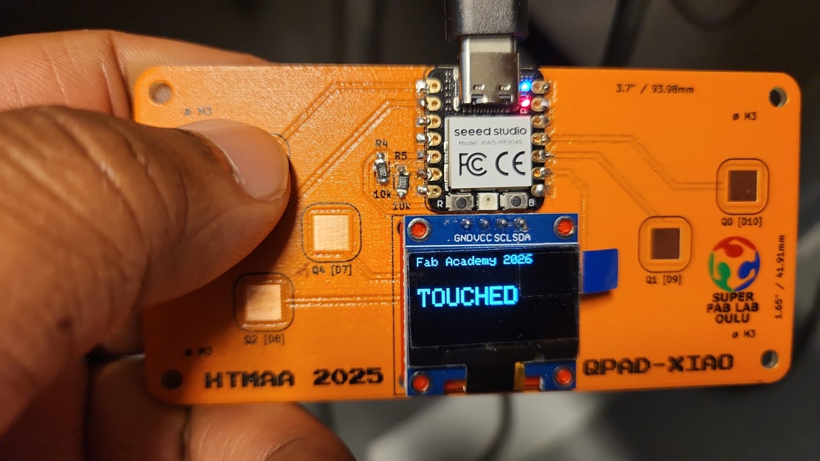
Final Working Logic
- WAITING: OLED displays WAITING and NeoPixel turns red.
- TOUCHED: OLED displays TOUCHED and NeoPixel turns green.
Observation: This experiment showed the importance of practical debugging. The initial logic looked correct theoretically, but real hardware behavior required Serial Monitor analysis and threshold tuning.
Challenges Faced
- Installing and configuring RP2040 board support
- Selecting the correct COM port during upload
- Understanding I2C pin mapping for the OLED display
- Fixing missing Arduino library dependencies
- Debugging unstable touch pad analog readings
- Understanding datasheet terminology and hardware behavior
Reflection
This week helped me understand the relationship between hardware, firmware, programming environments, and debugging tools. I learned that embedded programming is not only about uploading code, but also about checking wiring, board configuration, libraries, communication protocols, and real sensor behavior.
Successfully programmed and tested the Seeed Studio XIAO RP2040 using Arduino IDE, MicroPython, and MicroBlocks, including LED output, OLED display output, touch input, NeoPixel feedback, and Serial Monitor debugging.
Group Assignment Overview
The group assignment focused on comparing different embedded programming workflows, microcontroller architectures, toolchains, and communication methods. This helped us understand how different boards and environments behave before completing the individual programming task.
The external group assignment page is kept as a backup and for template consistency: Embedded Programming Group Assignment
Microcontroller Architecture Comparison
As a group, we compared different microcontroller platforms and discussed how architecture affects programming workflow, pin configuration, memory, speed, and peripheral support.
| Board / Chip | Key Features |
|---|---|
| RP2040 | Dual-core ARM Cortex-M0+, flexible GPIO, USB support, I2C, SPI, UART, PWM, ADC |
| AVR / Arduino-style boards | Simple programming workflow, mature ecosystem, useful for basic embedded experiments |
| ESP32 family | Integrated wireless communication, higher processing capability, useful for connected devices |
Programming Toolchain Comparison
We compared different development environments to understand the advantages and limitations of each workflow.
| Environment | Use | Observation |
|---|---|---|
| Arduino IDE | C/C++ embedded programming | Good for compiling, uploading, and using existing libraries |
| Thonny / MicroPython | Interactive Python-style programming | Useful for quick testing and direct board interaction |
| MicroBlocks | Visual block-based programming | Helpful for rapid testing and learning basic input/output logic |
| CircuitPython | Python-style embedded workflow | Convenient for supported boards and beginner-friendly experimentation |
Programming and Upload Workflow
The general embedded programming workflow involved selecting the correct board, selecting the correct port, writing or opening a program, compiling it, uploading it to the board, and checking the result through hardware output or serial communication.
- Connect the board using USB
- Select the correct board type
- Select the correct COM port
- Write or load a test program
- Compile and upload the program
- Observe output behavior
- Use Serial Monitor for debugging when needed
Serial Communication and Debugging
Serial communication was an important part of the group discussion because it allows the microcontroller to send debugging information to the computer. This is useful when checking sensor values, board state, program flow, and unexpected hardware behavior.
void setup() {
  Serial.begin(115200);
}

void loop() {
  Serial.println("Debug message from microcontroller");
  delay(1000);
}
Group Assignment Summary
The group assignment helped clarify how different boards and programming environments compare. It also made the individual assignment easier because I had a better understanding of board selection, toolchain setup, uploading, and serial debugging before working on my own XIAO RP2040 experiments.
Completed group exploration of embedded programming workflows, toolchains, microcontroller architectures, and communication methods.