Introduction
This week focuses on controlling output devices using a microcontroller. The objective was to interface and control an electromechanical actuator using a custom PCB developed in previous assignments.
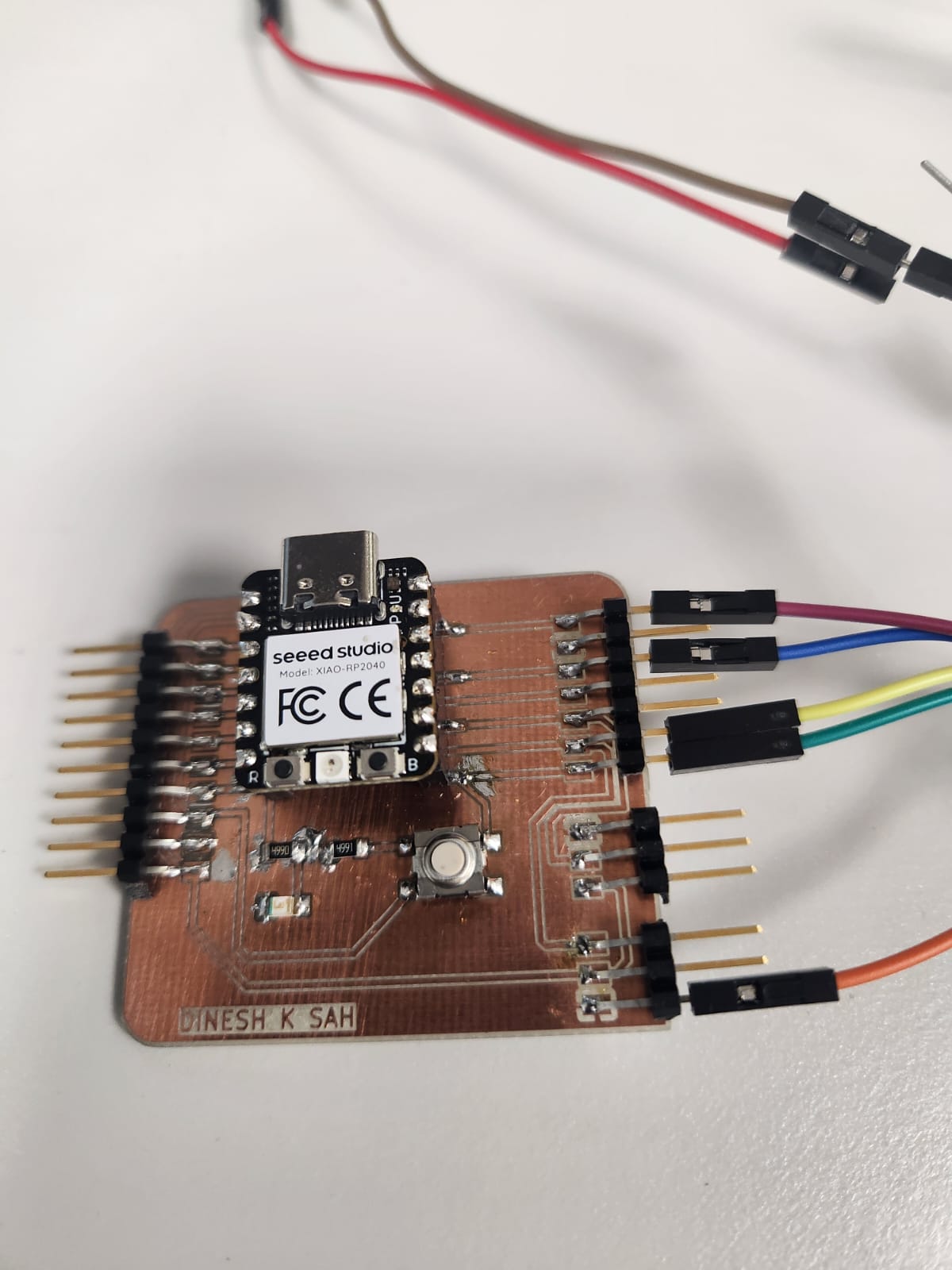
This assignment demonstrates a complete stepper motor control system using the DRV8825 driver and a custom XIAO RP2040 board.
Stepper Motor
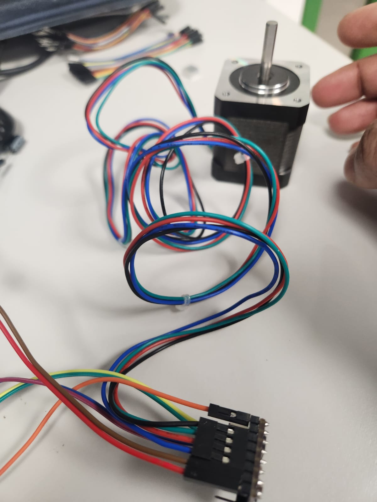
A stepper motor moves in discrete steps, allowing precise control of position and speed.
DRV8825 Driver
The DRV8825 converts low-power control signals (STEP & DIR) into high-power outputs.
Power Supply
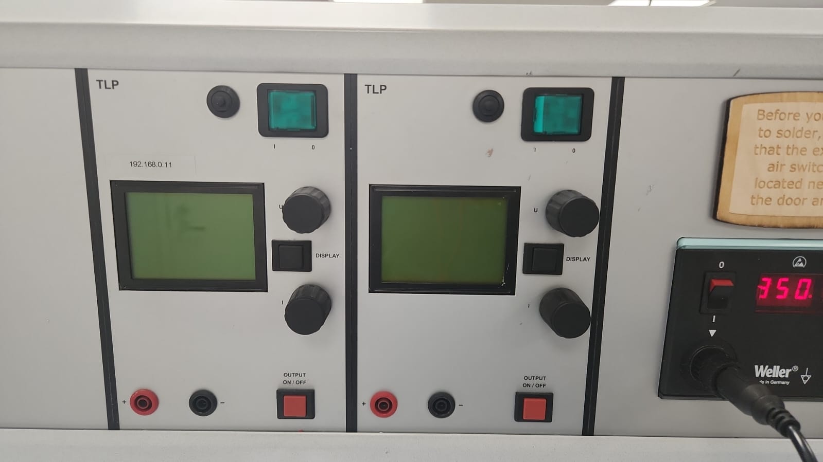
A 9V external power supply was used with current limiting at the begnning. Though it was not sufficient therefore it increased to 12V.
Capacitor Protection
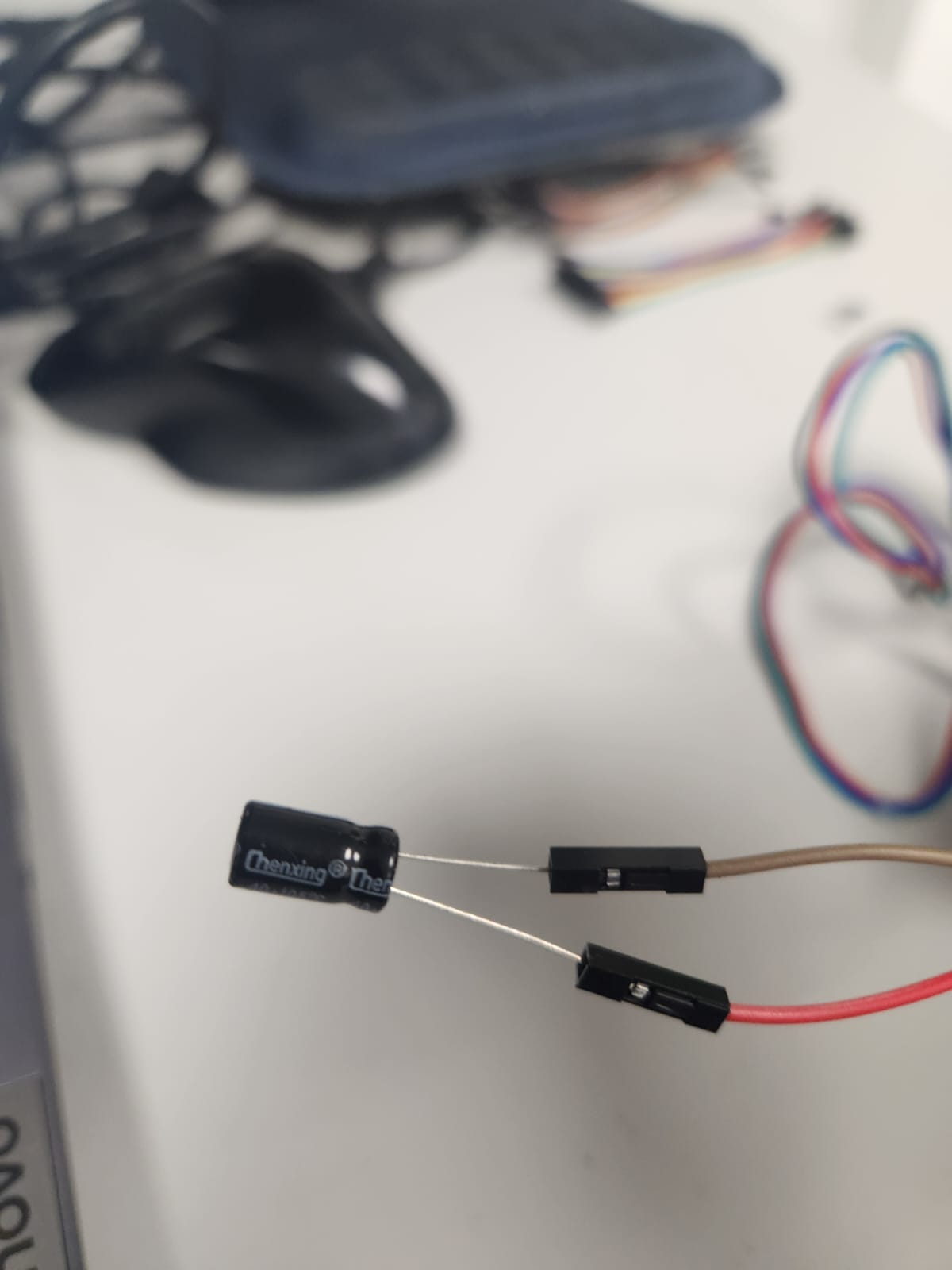
A 100µF capacitor stabilizes voltage and protects the driver.
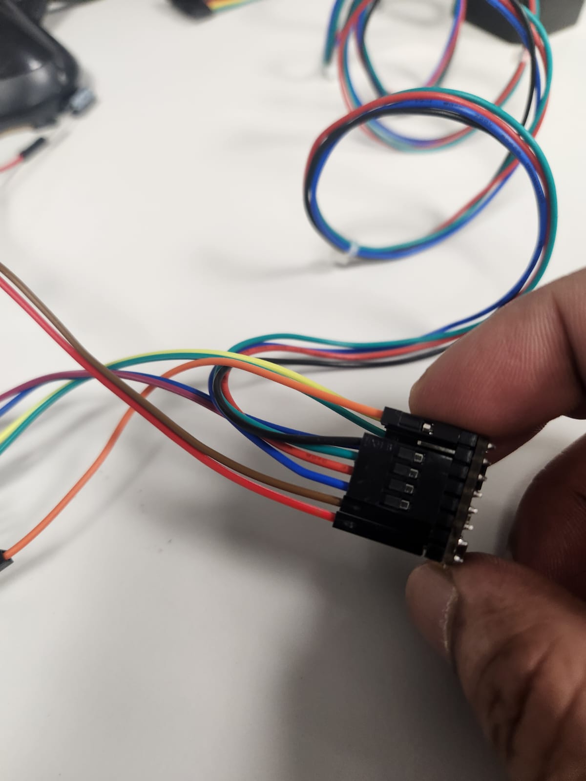
Wiring
| MCU | Driver | Function |
|---|---|---|
| D7 | DIR | Direction |
| D8 | STEP | Step |
| GND | GND | Common Ground |
Code
#include <AccelStepper.h>

#define DIR_PIN 7
#define STEP_PIN 8

AccelStepper stepper(AccelStepper::DRIVER, STEP_PIN, DIR_PIN);

void setup() {
  stepper.setMaxSpeed(1000);
  stepper.setAcceleration(200);
  stepper.moveTo(200);
}

void loop() {
  if (stepper.distanceToGo() == 0)
    stepper.moveTo(-stepper.currentPosition());

  stepper.run();
}
Results
Motor rotated smoothly in both directions confirming correct setup.