Week 12: Machine Design
Note: My English writing skills are limited. For this documentation, I have used AI assistance for parts of the translation.
Date: April 9 - 15, 2026
Group Assignment
Our group built a whiteboard drawing robot. It can draw pictures on a vertical surface automatically.
We used stepper motors and a RAMPS board from an old 3D printer. The robot runs on Marlin firmware and Makelangelo software.
Team roles:
| Member | Role |
|---|---|
| Yoshi | Electronics, firmware, and software |
| Bara (me) | Mechanical parts design, 3D printing, and video |
Special thanks to Yoshi. He is the best engineer on our team. His work made the project a success.
What I Learned
- Old parts can still be useful with good design.
- Splitting work by skill helps the team move faster.
- The robot worked on the first test. Only small vibration was left to fix.
Individual Assignment: Mechanical Parts
I designed and printed three types of parts for the robot.
| Part | Description |
|---|---|
| Motor mount | Clamps the NEMA 17 motor to the top edge of the whiteboard |
| Belt end | Holds the end of the GT2 belt |
| Pen holder | Holds the pen and moves it up and down |
Motor Mount
First, I planned the structure with a sketch.
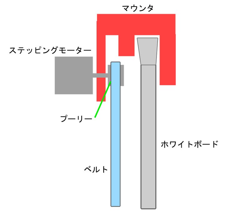
The mount hangs on the top edge of the whiteboard like a shoulder strap. No screws are needed to attach or remove it.
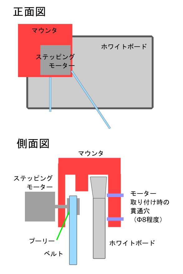
I drew a front view and side view to check the motor, pulley, and belt positions.
I then made a technical drawing in JW-CAD with full dimensions.
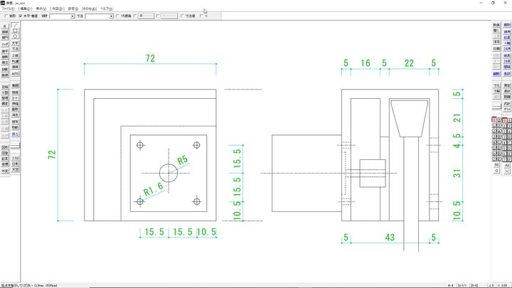
Key dimensions:
| Item | Value |
|---|---|
| Outer size | 72 × 72 × 53 mm |
| NEMA 17 screw holes | 31 × 31 mm pitch (M3) |
| Shaft hole | Ø10 mm |
| Driver access holes (back) | Ø8 mm × 2 |
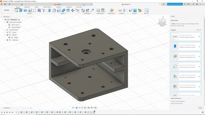
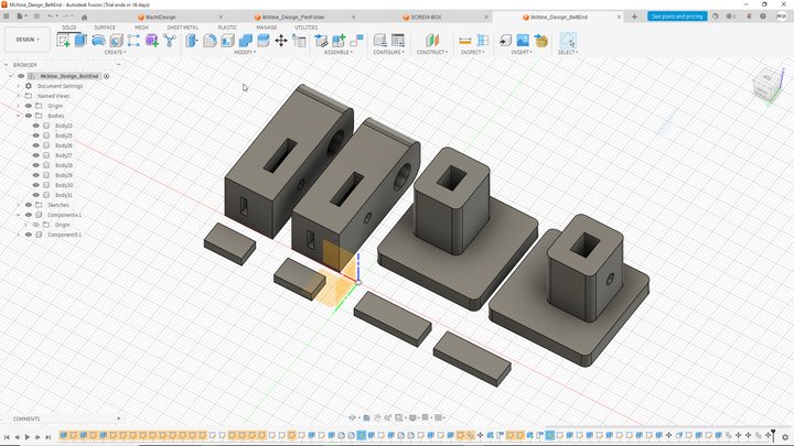
Finally, I built the 3D model in Fusion 360.
Belt End and Pen Holder
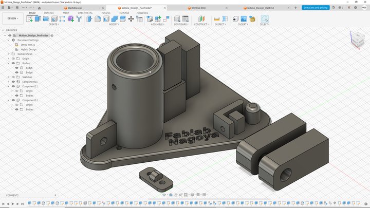
I also designed the belt end and pen holder in Fusion 360.
The belt end holds the tip of the GT2 belt securely.
The pen holder grips the pen and connects to the belt system. It has the FabLab Nagoya logo on the base.
3D Printing
I exported all parts as STL files and printed them with Bambu Lab H2S.
- Material: PETG (good strength and heat resistance)
- Walls: 4 / Infill: 40% Gyroid / Layer height: 0.2 mm
Video
I edited the video that shows our group work and the robot in action. You can watch it on the Group Work Page.
I make videos for my YouTube channel all the time, so this was my favorite part of the project. Please subscribe to my channel! → YouTube: @resprodiy
Design Files
| File | Description |
|---|---|
MachiDesign.f3d |
Fusion 360 file for the motor mount |
Mchine_Design_BeltEnd.f3d |
Fusion 360 file for the belt end |
Mchine_Design_PenFolder.f3d |
Fusion 360 file for the pen holder |
What I Learned
- I learned the standard dimensions of a NEMA 17 motor (42 × 42 mm body, 31 mm screw pitch).
- A clamp-style mount is easy to attach, but keeping it rigid is a challenge.
- When combining multiple parts into one system, matching dimensions is very important.
References
Last updated: April 2026