Final Project: Gecko State — Smart Reptile Habitat System
Section 1: Final Project Proposal
What I prepared for Week 01
Concept
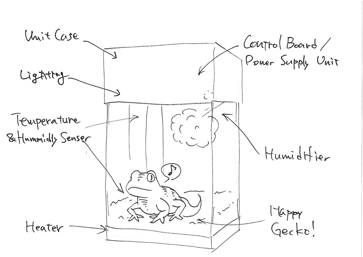
I want to build an automatic environment control system for my reptile terrarium.
My pet reptiles (geckos and snakes) need specific temperature and humidity. It is hard to keep the perfect environment all the time by hand.
The system will: - Monitor temperature and humidity inside the enclosure (two positions) - Automatically control the fan, heater, lighting, and humidifier - Let the user control each device manually from a web dashboard
What I Planned to Build
| Component | Plan |
|---|---|
| Custom PCB | Microcontroller board with sensors, fan driver, relay, Grove connectors |
| Terrarium Rack | CNC-milled wooden shelf to hold the tank |
| Web Dashboard | Real-time browser dashboard with history graph and device control |
| Gecko Emblem | Decorative emblem using molding and casting |
See Week 1 Documentation for the original project proposal.
Section 2: Final Project Development
What I built during the course — week by week
What I Made
Control Board — Integration Board (Custom PCB)
I designed and milled a custom PCB using KiCad and a CNC router.
| Component | Purpose |
|---|---|
| Seeed XIAO ESP32C6 | Main microcontroller (WiFi built-in) |
| SHT31 × 2 (I2C 0x44 / 0x45) | Temperature and humidity sensors (top / bottom) |
| Grove 2-ch SPDT Relay | Lighting (SW1/D0) and heater (SW2/D1) ON/OFF |
| Grove Water Atomization | Humidifier control (D2) |
| 4-pin PC fan × 2 | Intake / exhaust airflow (PWM + TACH) |
Gecko Shelf (Terrarium Rack)
I CNC-milled a wooden shelf (394 × 359 × 1094 mm) from 12 mm plywood. The terrarium sits on the top section. The shelves below store supplies.
Web Dashboard — Gecko State
A real-time browser-based dashboard running on my NAS.
- Live sensor display (temperature and humidity, top and bottom)
- History graph — 1D / 1W / 1M (Chart.js + Flask + SQLite)
- 5 device controls: lighting, intake fan, exhaust fan, heater, humidifier
- MQTT over WebSocket for real-time updates and control
Gecko Emblem
A decorative gecko emblem made by silicone molding and UV resin casting.
System Architecture
Physical Integration
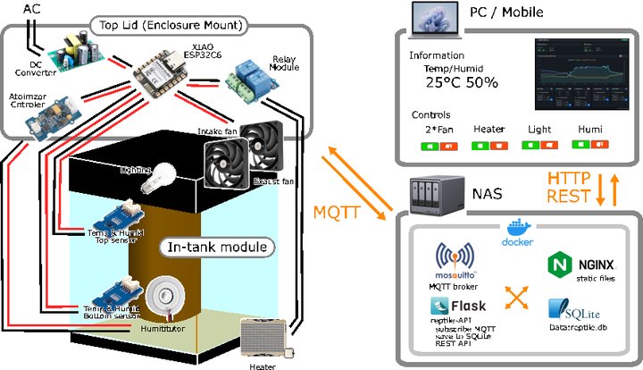 Full system — top lid (fans), integration board, and web dashboard
Software Architecture
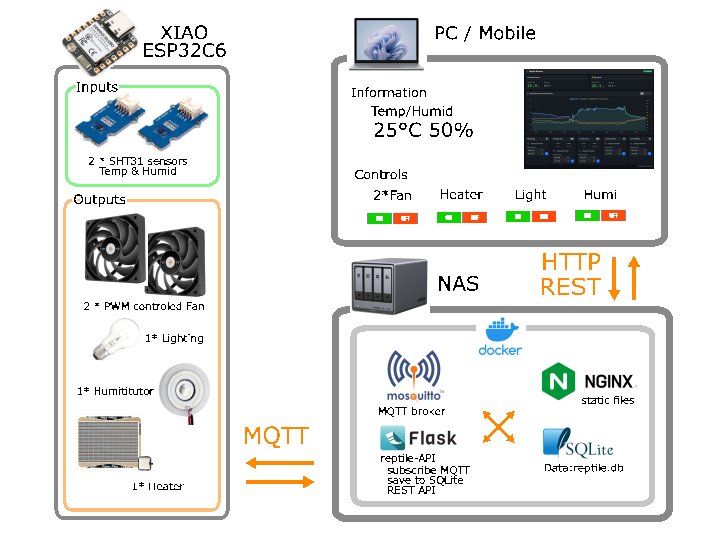 ESP32C6 → MQTT → NAS Docker → Browser dashboard
How It Works
- The ESP32C6 reads two SHT31 sensors every 5 seconds
- Sensor data is published via MQTT over WiFi
- The web dashboard receives data in real time (MQTT over WebSocket)
- Devices are controlled automatically based on sensor values and NTP schedule
- The user can enable manual override from the dashboard at any time
System Integration
To complete the system, all components are connected into one working unit:
| Part | Description | Method |
|---|---|---|
| Integration Board | Custom PCB with XIAO ESP32C6, relay connectors, fan connectors | KiCad → CNC milling → hand soldering |
| In-Tank Modules | Sensor mount, humidifier mount, cable guide | Fusion 360 → 3D print (PETG) |
| Top Lid | Holds enclosure, two 12V fans, and power connectors | JW-CAD → laser cut (MDF) |
For full details see Week 15: System Integration.
Weekly Progress
Week 1: Planning & Documentation ✅
- Created project website, outlined project concept
- See Week 1 Documentation
Week 2: Computer-Aided Design ✅
- 3D modeled terrarium and control box in Fusion 360
- See Week 2 Documentation
Week 3: Computer-Controlled Cutting ✅
- Press-fit kit with laser cutter, gecko sticker with vinyl cutter
- See Week 3 Documentation
Week 4: Embedded Programming ✅
- Button + LED circuit with XIAO SAMD21
- See Week 4 Documentation
Week 5: 3D Scanning and Printing ✅
- 3D printed gearbox (Bambu Lab P2S), 3D scanned figure with Hitem3D
- See Week 5 Documentation
Week 6: Electronics Design ✅
- Schematic and PCB design with KiCad, circuit simulation with Falstad
- See Week 6 Documentation
Week 7: Computer-Controlled Machining ✅
- Gecko Shelf — CNC-milled plywood (1094 mm tall, Maslow CNC)
- See Week 7 Documentation
Week 8: Electronics Production ✅
- Integration Board PCB — KiCad design, CNC milled, hand soldered
- See Week 8 Documentation
Week 9: Input Devices ✅
- Dual SHT31 sensors via I2C (address 0x44 / 0x45 with solder jumper)
- See Week 9 Documentation
Week 10: Output Devices ✅
- Fan PWM control via LEDC peripheral, RPM measurement via TACH interrupt
- See Week 10 Documentation
Week 11: Networking and Communications ✅
- MQTT publishing over WiFi, MQTT dashboard on NAS
- See Week 11 Documentation
Week 12: Machine Design ✅
- Whiteboard drawing robot — motor mount design and 3D printing
- See Week 12 Documentation
Week 13: Molding and Casting ✅
- Gecko emblem — CNC wax mold, silicone → UV resin casting
- See Week 13 Documentation
Week 14: Interface and Application Programming ✅
- Full MQTT dashboard: Bootstrap 5.3, Chart.js 4, MQTT.js 5
- Flask + SQLite backend with 1-month history
- See Week 14 Documentation
Week 15: System Integration ✅
- Integration Board completed: all 4 devices (fans, heater, humidifier, lighting) working
- Auto control + manual override via dashboard confirmed
- See Week 15 Documentation
Week 16: Wildcard ✅
- Automatic embroidery with Brother Skitch PP1 (Gecko + YouTube logo)
- See Week 16 Documentation
Week 17: Applications and Implications ✅
- Final project planning: purpose, materials, cost, processes
- See Week 17 Documentation
Week 18: Invention, IP and Income ✅
- Dissemination plan and licensing
- See Week 18 Documentation
Schedule
| Phase | 5/7 | 5/14 | 5/21 | 5/28 | 5/29 | 6/1 | 6/4 | 6/8 |
|---|---|---|---|---|---|---|---|---|
| Design | May 7 – 13 | |||||||
| Build | May 14 – 28 | |||||||
| Integration | May 29 – Jun 3 | |||||||
| Presentation | Jun 4 – 8 | |||||||
Section 3: Final Project
Final Video
The video is at the top of this page. ↑
Summary Slide
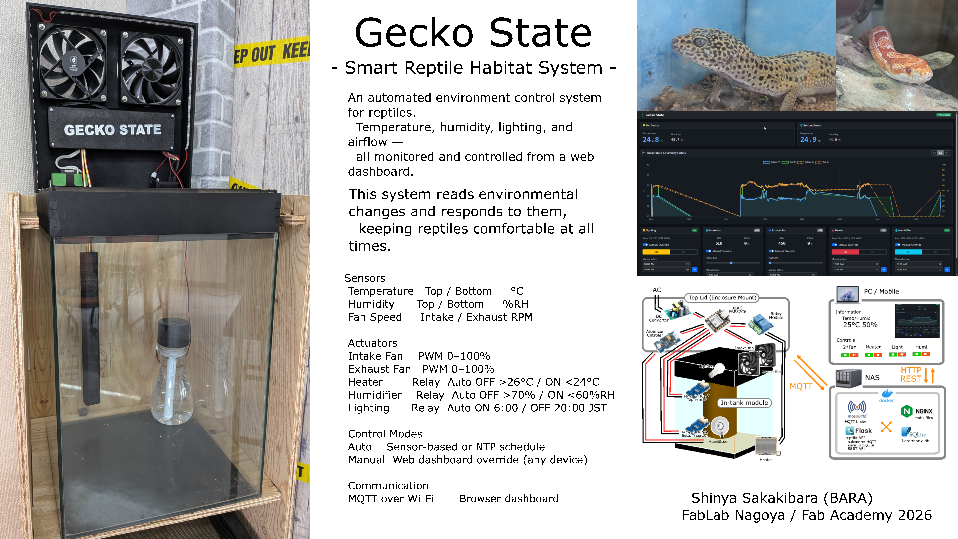
Build Process
Step 1: Power System
The system runs on AC 100V. I installed an IEC connector and a red power switch on the side of the tank lid. One switch turns the whole system on or off.
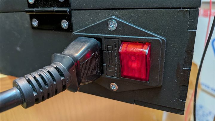 IEC connector and power switch — one switch controls the whole system
An AC-DC converter inside the tank changes 100V to 5V (for the microcontroller) and 12V (for the fans).
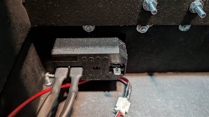 AC-DC converter mounted inside the tank frame
Step 2: Integration Board (GECKO 3.0)
The original board from Week 08 only had Grove connectors. I redesigned it in KiCad to add all connections needed for the full system.
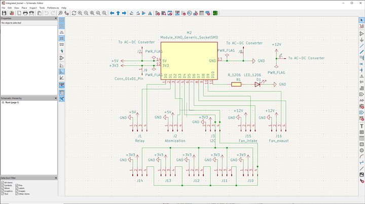 KiCad schematic — XIAO ESP32C6 at center with relay, fan, I2C, and atomizer connectors
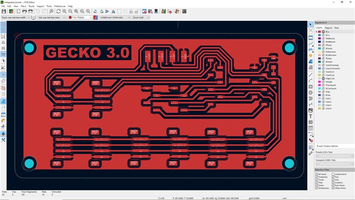 KiCad PCB layout (GECKO 3.0) — single-sided, CNC milled
I milled the board with a CNC router and soldered all components by hand.
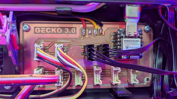 Completed GECKO 3.0 board with all cables connected
Step 3: Firmware
I wrote the firmware in Arduino IDE. It reads two SHT31 sensors, controls fan PWM, manages relay outputs, and publishes data via MQTT.
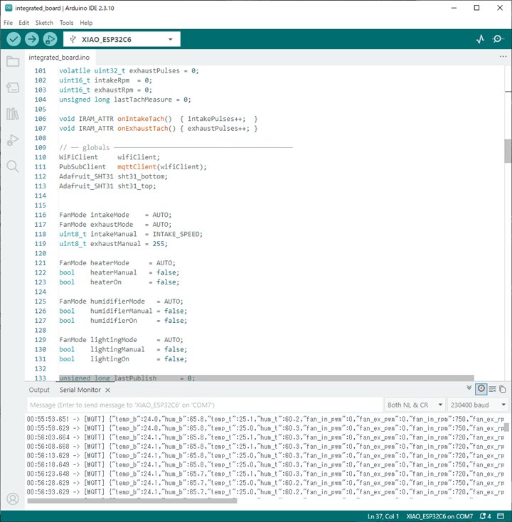 Writing and testing firmware in Arduino IDE — Serial Monitor shows live MQTT output
Step 4: Board Enclosure
I designed an enclosure in Fusion 360 to hold the integration board, AC-DC converter, and relay module. I 3D printed it in PETG (black, heat-resistant) and mounted it on the inside of the tank lid.
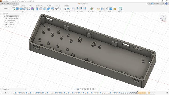 Fusion 360 enclosure design with mounting posts and cable openings
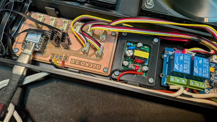 Assembled enclosure — GECKO 3.0, relay module, and DC-DC converter in one unit
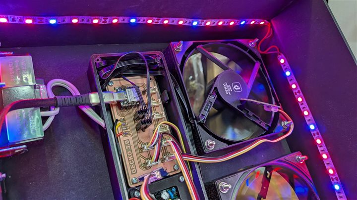 Enclosure installed on the tank lid — LED strip and fan visible nearby
Step 5: Fans
I installed two 4-pin 12V PWM fans on the tank lid: one intake and one exhaust.
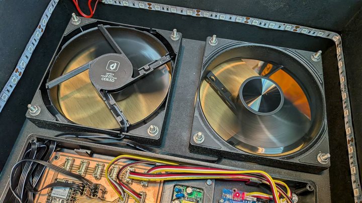 Two fans on the lid — left is intake (IN), right is exhaust (OUT)
Step 6: AC Heater Output
The reptile heater runs on AC 100V. A relay circuit inside the tank controls the power. An AC outlet on the outside lets me plug in the heater.
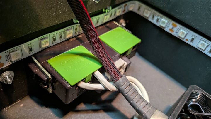 Relay circuit inside the tank — green covers protect the 100V terminals
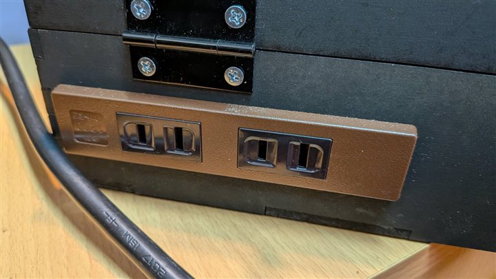 AC outlet on the outside of the tank — the heater plugs in here
Step 7: Sensor Case
I designed a sensor case in Fusion 360. It has a lid and ventilation slots so air can reach the SHT31 inside. A magnet on the back attaches it to the metal tank frame.
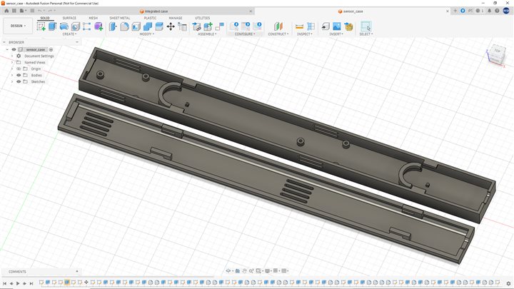 Fusion 360 sensor case design (body + lid)
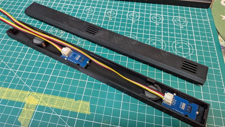 Two 3D printed cases — SHT31 boards inside, one for top and one for bottom
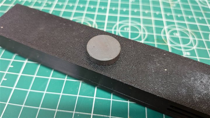 Magnet on the back — attaches to the tank frame
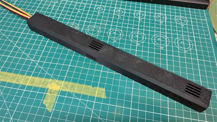 Lid closed — only ventilation slots visible
Step 8: Humidifier Attachment
I designed a custom attachment in Fusion 360 to mount an ultrasonic humidifier on a standard PET bottle. Three parts: a cup (holds the transducer), a nozzle adapter, and a screw cap.
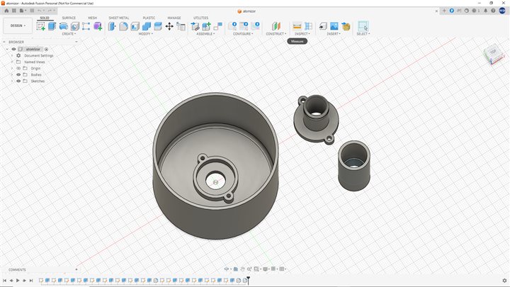 Fusion 360 design — cup, nozzle adapter, and screw cap
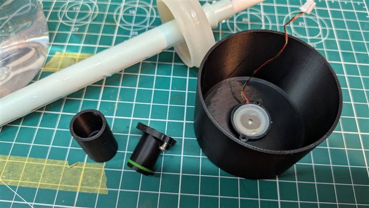 3D printed parts — transducer visible inside the cup
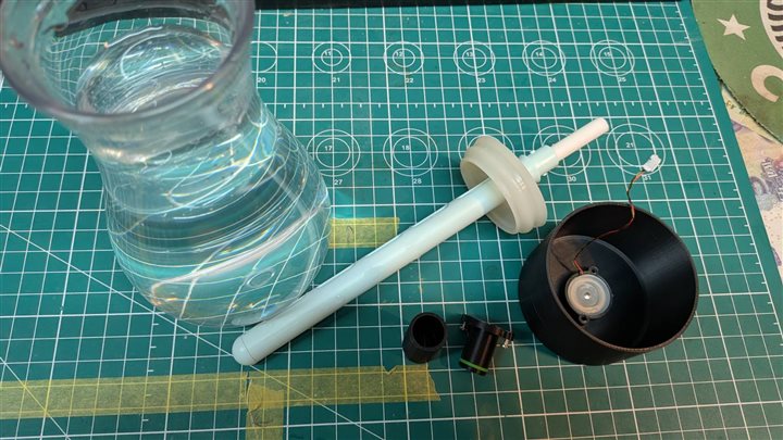 All parts laid out with the PET bottle water tank
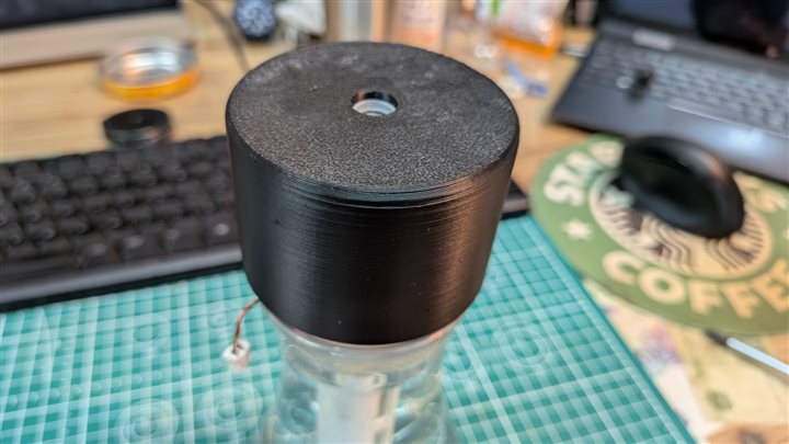 Completed assembly on the PET bottle
Step 9: Dashboard
I built the Gecko State dashboard using HTML, Bootstrap 5.3, Chart.js 4, and MQTT.js 5. It shows live sensor readings, a history chart with 1H–1M range buttons, and controls for all 5 devices.
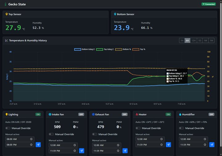 Gecko State dashboard — sensor display, 6H chart, and 5 device control cards
The dashboard is fully responsive. It also works on smartphones.
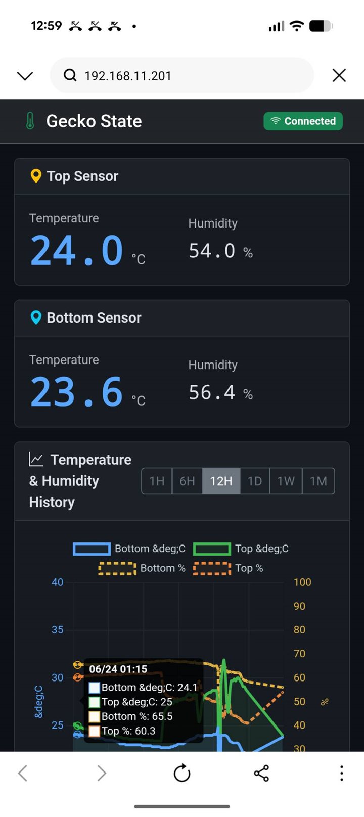 Gecko State dashboard on a smartphone — same layout, usable on mobile
Step 10: Results
After connecting all components, I ran end-to-end tests.
- ✅ Fans: PWM speed control + live RPM display
- ✅ Heater: auto control (ON < 24°C / OFF > 26°C) + manual override
- ✅ Humidifier: auto control (ON < 60% / OFF > 70%RH) + manual override
- ✅ Lighting: NTP schedule (6:00–20:00 JST) + manual override
- ✅ Dashboard: real-time monitoring and control from any browser on the local network
Gecko State — System Description
This system reads environmental changes and responds to them, keeping reptiles comfortable at all times.
Sensors
| Sensor | Position | Measurement |
|---|---|---|
| SHT31 | Top | Temperature (°C), Humidity (%RH) |
| SHT31 | Bottom | Temperature (°C), Humidity (%RH) |
| Fan TACH signal | Intake / Exhaust | Fan speed (RPM) |
Actuators & Control Logic
| Device | Hardware | Auto Mode | Manual Mode |
|---|---|---|---|
| Intake Fan | 4-pin PC fan, LEDC PWM | Always on (set speed) | PWM slider 0–100% |
| Exhaust Fan | 4-pin PC fan, LEDC PWM | Always on (set speed) | PWM slider 0–100% |
| Heater | Grove 2-ch SPDT Relay (SW2/D1) | ON < 24°C / OFF > 26°C | Dashboard toggle |
| Humidifier | Grove Water Atomization (D2) | ON < 60% / OFF > 70%RH | Dashboard toggle |
| Lighting | Grove 2-ch SPDT Relay (SW1/D0) | ON 6:00 / OFF 20:00 JST (NTP) | Dashboard toggle |
Reptiles are generally sensitive to bright light, so I use a dim grow light designed for plants. The tank also contains live plants — this lighting works well for both.
Integration Board (Custom PCB)
Designed in KiCad (GECKO 3.0), milled on a LUNYEE 3018 PRO MAX, and hand-soldered. All Grove connectors, fan headers, relay outputs, and AC power terminals are on a single board.
Dashboard
The Gecko State web dashboard runs as a static HTML page hosted on a local NAS. It connects to the MQTT broker over WebSocket and updates in real time.
| MQTT Topic | Direction | Purpose |
|---|---|---|
reptile/sensor |
ESP32 → Dashboard | Live sensor data |
reptile/fan/in/cmd |
Dashboard → ESP32 | Intake fan speed |
reptile/fan/ex/cmd |
Dashboard → ESP32 | Exhaust fan speed |
reptile/relay/heat/cmd |
Dashboard → ESP32 | Heater on/off |
reptile/relay/hum/cmd |
Dashboard → ESP32 | Humidifier on/off |
reptile/relay/light/cmd |
Dashboard → ESP32 | Lighting on/off |
Results
- ✅ Fans: PWM speed control + live RPM readout
- ✅ Heater: auto temperature control (24–26°C) + manual override
- ✅ Humidifier: auto humidity control (60–70%RH) + manual override
- ✅ Lighting: NTP schedule (6:00–20:00 JST) + manual override
- ✅ Dashboard: real-time monitoring and control from any device on the network
Bill of Materials (BOM)
| Item | Qty | Unit Price | Total | Source |
|---|---|---|---|---|
| Seeed XIAO ESP32C6 | 1 | $6.50 (¥1,000) | $6.50 | Seeed Studio |
| Sensirion SHT31 (Grove) | 2 | $10.30 (¥1,600) | $20.60 | Switch Science |
| Grove 2-ch SPDT Relay | 1 | $7.75 (¥1,200) | $7.75 | Switch Science |
| Grove Water Atomization | 1 | $6.45 (¥1,000) | $6.45 | Switch Science |
| 4-pin PC fan 60mm 12V | 2 | $3.90 (¥600) | $7.75 | Amazon |
| FR1 PCB blank (100×100mm) | 2 | $1.30 (¥200) | $2.60 | FabLab |
| AC-DC converter 5V,12V 2A | 1 | $5.15 (¥800) | $5.15 | Amazon |
| PETG filament (250g) | 1 | $5.15 (¥800) | $5.15 | Bambu Lab |
| MDF 3mm (300×300mm) | 1 | $1.95 (¥300) | $1.95 | Home center |
| Miscellaneous (wire, connectors, screws) | — | — | $6.45 | — |
| Total | ~$70 (¥10,800) |
Questions and Answers
What does it do? Gecko State automatically controls the temperature, humidity, lighting, and airflow inside a reptile terrarium. It monitors the environment with two sensors and responds with relays and fans. The user can also override any device manually from a web dashboard.
What did you design? - Integration Board (custom PCB) — KiCad schematic and PCB layout - Gecko Shelf — CNC-milled plywood rack (1094 mm tall) - In-tank modules — 3D-printed PETG mounts and guides - Top lid — laser-cut MDF - Web dashboard — HTML/JS frontend + Python Flask backend - Gecko emblem — silicone mold + UV resin cast
What materials and components were used? See BOM above.
How much did it cost? Approximately 18,700 JPY (~125 USD) total.
What processes were used? CNC milling (PCB + shelf + wax mold), 3D printing, laser cutting, hand soldering, silicone molding, UV resin casting, embedded programming (Arduino/ESP32), web development.
What worked? What didn't? All four auto-control functions and manual overrides work correctly. The main challenge was the PubSubClient MQTT buffer (default 256 bytes was too small — increased to 512 bytes to fix MQTT receive failures). Fan minimum speed (~150 RPM at PWM=0) is a hardware limitation of 4-pin PC fans and is accepted as an idle state.
How was it evaluated? Full end-to-end test: sensors → MQTT → dashboard → device response. All 5 devices confirmed working in both auto and manual modes.
Files for Replication
Firmware & Software
| File | Description |
|---|---|
integrated_board.ino |
ESP32C6 firmware — all device control |
index.html |
Gecko State web dashboard (frontend) |
app.py |
Flask history API (backend) |
Integration Board (GECKO 3.0) — KiCad
| File | Description |
|---|---|
Integrated_borad.kicad_sch |
KiCad schematic |
Integrated_borad.kicad_pcb |
KiCad PCB layout |
Integrated_borad-F_Cu.gbr |
Gerber — copper layer |
Integrated_borad-Edge_Cuts.gbr |
Gerber — board outline |
front.ngc |
G-code — isolation milling |
outline.ngc |
G-code — board cutout |
Reptile Monitor PCB — KiCad
| File | Description |
|---|---|
Reptile_Monitor.kicad_sch |
KiCad schematic |
Reptile_Monitor.kicad_pcb |
KiCad PCB layout |
3D CAD (Fusion 360 .f3d)
| File | Description |
|---|---|
Integrated case.f3d |
Board enclosure body |
Integrated case top.f3d |
Board enclosure lid |
sensor_case.f3d |
In-tank sensor case |
atomizor.f3d |
Humidifier attachment |
CNC
| File | Description |
|---|---|
Gecko_Shelf_Cut.dxf |
Gecko Shelf CNC cut file |
License
This project is released under the Creative Commons Attribution Non-Commercial Share-Alike 4.0 International License (CC BY-NC-SA 4.0).
You are free to use, modify, and share this work for non-commercial purposes, as long as you give credit and share under the same license.
Acknowledgments
- FabLab Nagoya — machine access, materials, and support throughout the course
- Fab Academy instructors — global reviews and technical guidance
- Seeed Studio — XIAO ESP32C6 and Grove module ecosystem
- Neil Gershenfeld and the Fab Academy community — for building this program
References
- Week 17: Applications and Implications
- Week 18: Invention, IP and Income
- Fab Academy 2026
- Seeed Studio XIAO ESP32C6
- Grove 2-Channel SPDT Relay
- Grove Water Atomization
Last updated: June 2026