Week 15: System Integration
Note: My English writing skills are limited. For this documentation, I have used AI assistance for parts of the translation.
Date: May 6 - 13, 2026
System Diagram
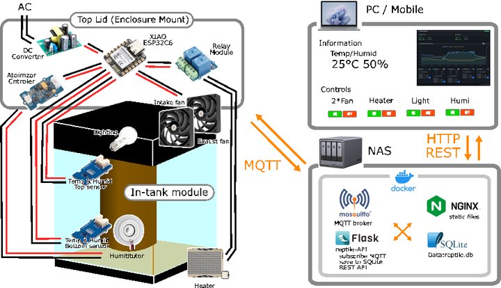
The top lid holds the enclosure (XIAO ESP32C6, DC converter, relay module, atomizer controller) and two fans. Inside the tank, sensors, lighting, humidifier, and heater are connected to the control board. The XIAO ESP32C6 sends data to the NAS via MQTT, and the user controls the system from a web dashboard.
What I Have Built So Far
| Week | Output |
|---|---|
| Week 06 | Test Board (KiCad design — LED + button) |
| Week 08 | Reptile Monitor PCB (XIAO ESP32C6, Grove ×4, SMD assembly) |
| Week 09 | Input device testing (SHT31 ×2, I2C dual sensor) |
| Week 10 | Output device testing (OLED, motor driver, fan ON/OFF) |
| Week 11 | WiFi + MQTT communication, web dashboard |
| Week 14 | Production dashboard (Bootstrap + Chart.js + Flask + SQLite) |
The current control board is only a XIAO mount + Grove connection board. Power supply and output terminals are not yet integrated.
Remaining Work
1. Integration Board (New Design)
The current board cannot handle AC power input or heater output. I will redesign it from scratch in KiCad, combining all functions on a single board.
| Component | Purpose |
|---|---|
| AC 100V input terminal | Connect to mains power |
| AC-DC converter 5V | Power for microcontroller and sensors |
| AC-DC converter 12V | Power for fans |
| AC 100V heater output terminal | ON/OFF control via SSR |
| XIAO ESP32C6 socket | Removable microcontroller mount |
| Grove connectors (multiple) | Connect all peripheral modules |
Schematic and PCB pattern already designed:
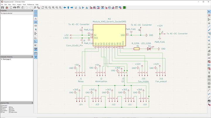 KiCad schematic — XIAO ESP32C6 at center with Relay, Atomization, I2C, and Fan connectors
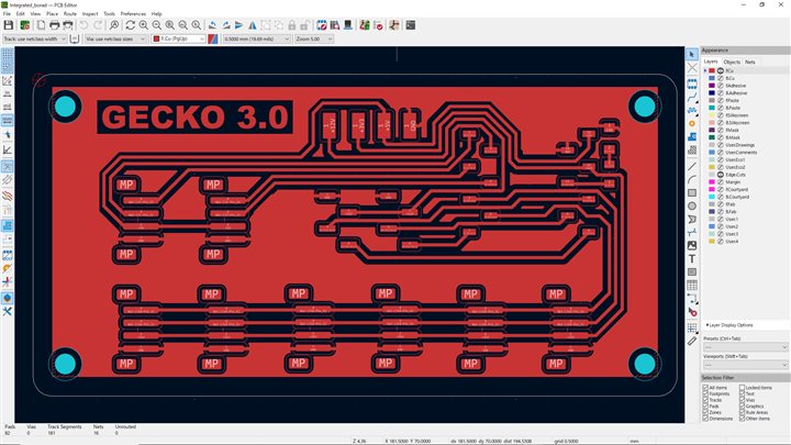 KiCad PCB pattern (GECKO 3.0) — single-sided, to be fabricated by CNC milling
2. Board Enclosure
I will design and build a box to hold the integrated board, power modules, and Grove relay (for output). It will be designed to mount on the top lid of the tank.
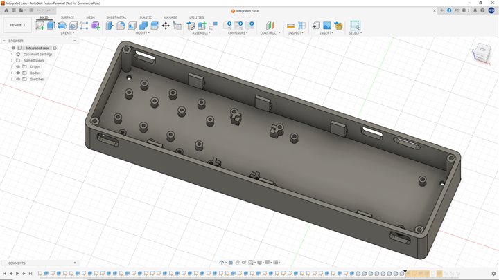 Fusion 360 enclosure design — holds the board, power modules, and all wiring
3. In-Tank Modules
I will 3D print the following modules to place inside the terrarium.
Temperature / Humidity Sensor Case
A case to hold the SHT31 sensors with a magnet mount for attaching to the tank wall.
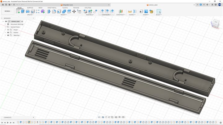 Fusion 360 sensor case design (body + lid) — ventilation slots allow airflow to reach the sensor
Humidifier Attachment
An attachment to mount the ultrasonic humidifier module onto a standard PET bottle.
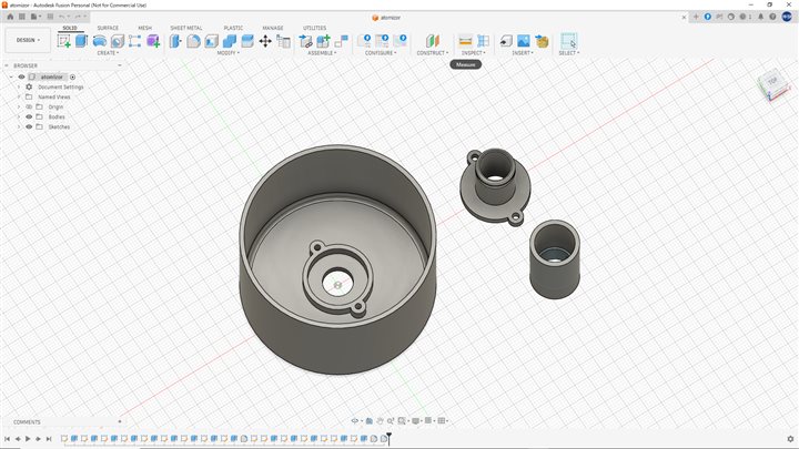 Fusion 360 humidifier attachment — mounts the humidifier unit onto a PET bottle water supply
Other in-tank modules to be designed:
| Module | Purpose |
|---|---|
| Pet bottle mount | Hold the water supply bottle |
| Water dish | Drinking water for reptiles, helps with humidity |
| Cable guide | Organize wiring inside the tank |
4. Top Lid (Enclosure Mount)
I will design and build a top lid that attaches to the existing tank frame. All control equipment will be mounted on this lid.
| Equipment | Spec |
|---|---|
| Enclosure box | Integrated board + power modules |
| Intake fan | 12V 4-pin PWM × 1 |
| Exhaust fan | 12V 4-pin PWM × 1 |
| Power input | AC 100V connector |
| Power output | Heater terminal |
Design requirements: - Fits the existing tank frame - Can be removed without tools (for maintenance)
Packaging Design
All enclosures are designed to give the system a finished-product appearance:
- Material: PETG — chosen for heat and humidity resistance inside the terrarium
- Color: Matte black — matches the tank frame and gives a clean look
- Fasteners: M3 bolts and nuts throughout — consistent and easy to disassemble for maintenance
- Cable management: All connectors use JST-style housings; wiring is routed inside the enclosure to keep the exterior clean
- Mounting: Tool-free attachment to the tank frame wherever possible
The enclosure box holds the integration board, power modules, and relay unit as a single removable unit. This makes the system look like a finished product rather than a collection of exposed circuits.
Methods
1. Integration Board
| Step | Tool / Method |
|---|---|
| Schematic & PCB design | KiCad (Schematic Editor → PCB Editor) |
| G-code generation | pcb2gcode |
| Board fabrication | CNC milling (same process as Week 08) |
| Component assembly | Hand soldering with a soldering iron |
2. Enclosure
| Step | Tool / Method |
|---|---|
| 3D modeling | Fusion 360 |
| Fabrication | 3D printer (Bambu Lab) |
| Material | PETG (heat and humidity resistant) |
| Assembly | M3 bolts and nuts |
3. In-Tank Modules
| Step | Tool / Method |
|---|---|
| 3D modeling | Fusion 360 |
| Fabrication | 3D printer (Bambu Lab) |
| Material | PETG (recommended for humid environments) |
4. Top Lid
| Step | Tool / Method |
|---|---|
| 2D design | JW-CAD |
| Fabrication | Laser cutter |
| Material | MDF |
| Attachment | Fits onto the existing tank frame |
5. Firmware
| Step | Tool / Method |
|---|---|
| Development | Arduino IDE |
| Board | XIAO ESP32C6 |
| Changes | Update pin assignments (D6/D7 for fan PWM, D8/D9 for TACH) |
6. System Integration
All parts are assembled and connected step by step. Each module is tested individually before full system testing. Final check: sensor → MQTT → dashboard → output control (end-to-end).
Schedule
| Phase | 5/7 | 5/14 | 5/21 | 5/28 | 5/29 | 6/1 | 6/4 | 6/7 |
|---|---|---|---|---|---|---|---|---|
| Design | May 7 – 13 | |||||||
| Build | May 14 – 28 | |||||||
| Integration | May 29 – 31 | |||||||
| Testing | Jun 1 – 3 | |||||||
| Presentation | Jun 4 – 7 | |||||||
System Integration — Final Build
The complete build process and actual integration of all components is documented on the Final Project page.
➡ Final Project: Gecko State — System Integration
What I Learned
- Power design is the most important part when integrating individual components into one system.
- An integrated board that handles both AC 100V and low voltage (5V / 12V) needs careful safety design.
- Writing out a clear schedule helped me see the full scope of remaining work and set priorities.