Week 8: Electronics Production
Note: My English writing skills are limited. For this documentation, I have used AI assistance for parts of the translation.
Date: March 12 - 18, 2026
What I Did This Week
I made the control board for my Smart Reptile Habitat System. I designed the PCB in Week 6. This week I made it with a CNC milling machine and soldered all the parts.
📋 Assignment
Group Assignment
✅ Characterize the design rules for your in-house PCB production process ✅ Submit a PCB design to a board house
What We Learned from the Group Work
We tested trace width and clearance limits on our lab's CNC milling machine (LUNYEE 3018 PRO MAX).
Machine setup: - Endmill: 0.4mm and 0.8mm - Material: Copper clad laminate (non-fiberglass, 1.6mm) - Software: CNCjs + MODS
Test results:
| Parameter | Result |
|---|---|
| Minimum trace width | 10 mil (0.254mm) — below this, traces break |
| Risky trace width | 7–12 mil — sometimes breaks |
| Minimum clearance | 20 mil (0.508mm) |
Traces thinner than 0.003 inch (7.5 mil) were broken. Traces between 0.003–0.005 inch were sometimes risky. I used 0.5mm (about 20 mil) for my board design, which was safe.
Individual Assignment
✅ Make and test an embedded microcontroller system that you designed
🔧 Individual Assignment: Make and Test a PCB
I made the Reptile Monitor board. This board controls temperature, humidity, fan, lighting, and humidifier for a reptile cage.
Board features: - XIAO ESP32C6 (WiFi microcontroller) - 4 Grove connectors (I2C × 1, Digital × 3) - LED indicator (D10)
Step 1: Design the Schematic
I used KiCad 9.0 to draw the circuit.
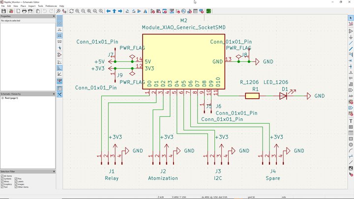 Reptile Monitor schematic — XIAO ESP32C6 with 4 Grove connectors and LED
Components:
| Reference | Part | Value |
|---|---|---|
| M2 | XIAO ESP32C6 socket | Module_Seeed_XIAO_Generic_SocketSMD |
| J1 | Grove connector | Relay (D0/D1) |
| J2 | Grove connector | Water Atomization (D2/D3) |
| J3 | Grove connector | I2C — SHT31 × 2 + Motor Driver (D4/D5) |
| J4 | Grove connector | Spare (D6/D7) |
| R1 | Resistor | SMD 1206 / 1kΩ |
| D1 | LED | SMD 1206 |
I ran the ERC (Electrical Rules Check). Some errors appeared, but I fixed them. The final result was 0 errors.
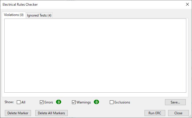 ERC — Violations: 0
Step 2: Design the PCB Layout
I placed all components in KiCad PCB Editor. It was my first time using this tool, but I think the routing looks clean.
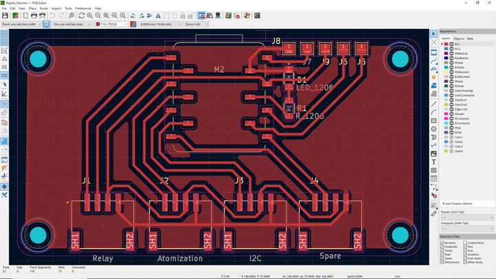 PCB layout — XIAO socket at top, 4 Grove connectors at bottom
Design rules: - Trace width: 0.5mm - Clearance: 0.5mm - GND copper fill (Direct connection) - No-Net fill zone (to reduce CNC milling area) - 4 mount holes (M3)
I ran the DRC (Design Rules Check). The result was 0 errors. There were 10 warnings for "Isolated copper fill" from the No-Net zone. This is expected — the warnings are not a problem.
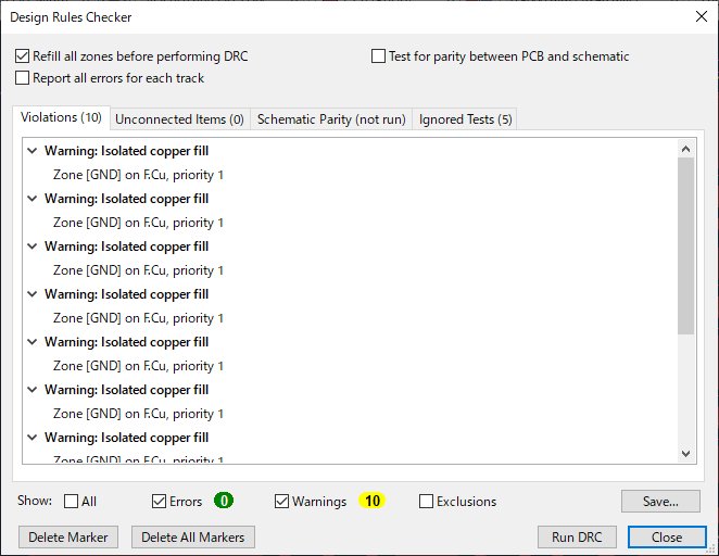 DRC — Errors: 0, Warnings: 10 (all isolated copper fill — expected)
Step 3: Export Gerber Files
I exported Gerber files from KiCad.
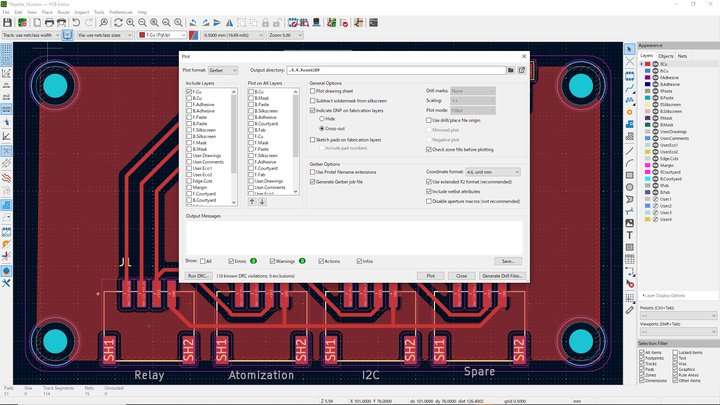 KiCad Plot dialog — F.Cu and Edge.Cuts layers exported
Exported files:
| File | Purpose |
|---|---|
Reptile_Monitor-F_Cu.gbr |
Copper traces |
Reptile_Monitor-Edge_Cuts.gbr |
Board outline |
Step 4: Generate G-code with pcb2gcodeGUI
I used pcb2gcodeGUI to convert Gerber files to G-code.
DXF is a de facto standard CAD format. Many tools can read it — CAD software, CAM software, and CNC machines. I also used KrabzCAM in Week 7 for wood CNC milling. This week I used pcb2gcodeGUI because it reads Gerber files directly and generates clean toolpaths for PCB isolation milling. In fact, I tried KrabzCAM first — the paths were broken and I wasted a lot of time.
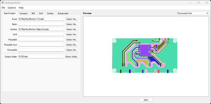 pcb2gcodeGUI — Gerber files loaded, PCB toolpath preview
Settings:
| Parameter | Value |
|---|---|
| Cut depth | 0.1mm |
| Feed rate | 240 mm/min |
| Spindle speed | 10,000 RPM |
I loaded the G-code in Candle to check the toolpath before milling.
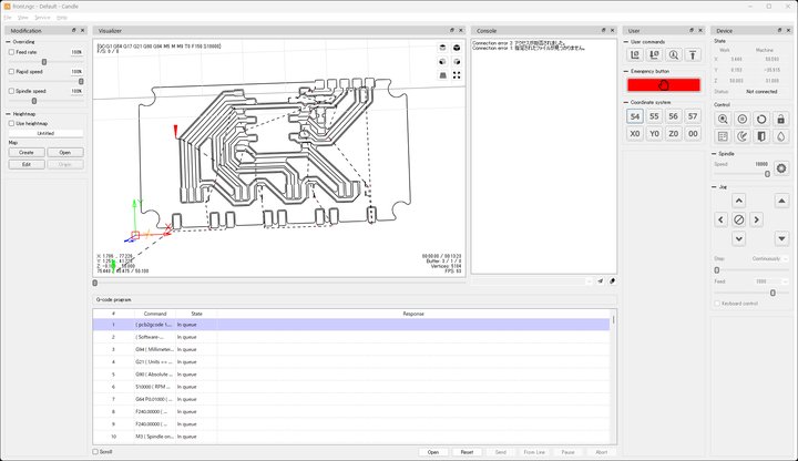 Candle — front.ngc loaded, toolpath preview looks correct
Step 5: Mill the PCB
Board Fixture
Yoshi designed a 3D-printed PCB holder for our lab's CNC machine. It holds the board flat and tight with screws.
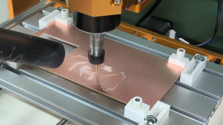 The white 3D-printed holder keeps the board in place during milling.
Setting the Origin
- Move the endmill to the start position by hand
- Click "Set Zero" in Candle
- Z height is set automatically by the auto-leveling probe
Auto-Leveling with Candle
Candle has a built-in auto-leveling feature. It scans the board surface and corrects for any tilt automatically. I just attached a probe clip to the endmill and ran the scan.
For more details about CNC setup, see Week 7: Computer-Controlled Machining.
Milling
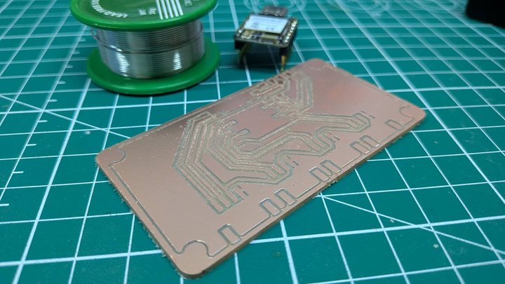
I used a CNC milling machine to cut the board.
The machine removed copper around the traces to make isolation channels. After milling, the board looks like this:
 Milled PCB — traces and pads are visible
Step 6: Solder Components
I soldered all SMD components by hand.
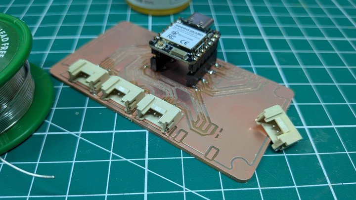 Soldering Grove connectors and XIAO socket
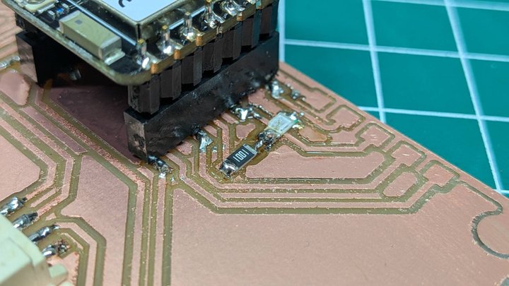 Close-up — 1kΩ resistor (1001) and LED next to XIAO socket
Soldering order: 1. SMD resistor (1kΩ) 2. SMD LED 3. Grove connectors × 4 4. XIAO ESP32C6 socket
Step 7: Test the Board
First I checked continuity with a multimeter.
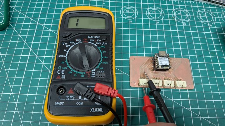 Multimeter continuity check — no short circuits found
Then I plugged in the XIAO ESP32C6 and uploaded a Blink sketch.
Test code (Arduino IDE):
const int LED_PIN = D10;

void setup() {
  Serial.begin(115200);
  pinMode(LED_PIN, OUTPUT);
  Serial.println("Reptile Monitor - LED Blink Test");
}

void loop() {
  digitalWrite(LED_PIN, HIGH);
  Serial.println("LED ON");
  delay(1000);

  digitalWrite(LED_PIN, LOW);
  Serial.println("LED OFF");
  delay(1000);
}
Result: ✅ LED blinks correctly!
LED blink test — D10 blinks at 1 second interval
📦 Design Files
All files are in docs/files/week08/.
| File | Description |
|---|---|
| Reptile_Monitor.kicad_sch | KiCad schematic |
| Reptile_Monitor.kicad_pcb | KiCad PCB layout |
| Reptile_Monitor-F_Cu.gbr | Gerber — copper layer |
| Reptile_Monitor-Edge_Cuts.gbr | Gerber — board outline |
| front.ngc | G-code — isolation milling |
| outline.ngc | G-code — board cutout |
🔗 Connection to Final Project
This board is the control center for my Smart Reptile Habitat System.
- XIAO ESP32C6 → WiFi communication + sensor control
- Grove I2C (J3) → Connect SHT31 temperature/humidity sensors
- Grove Digital (J1) → Control relay for lighting and heater
- Grove Digital (J2) → Control ultrasonic humidifier
- Grove Digital (J4) → Spare for future expansion
🔧 Problems and Solutions
Problem: CAM software — disconnected paths in KrabzCAM
What Happened: I tried to use KrabzCAM (the same tool I used in Week 7). But KrabzCAM only works with closed paths. The DXF from KiCad had open paths. KrabzCAM ignored them.
How I Solved It: I used pcb2gcodeGUI instead. It reads Gerber files directly. Gerber is the standard PCB format. There are no path problems.
What I Learned: Use the right tool for the job. KrabzCAM is great for wood CNC. pcb2gcode is better for PCB milling.
✅ Evaluation Checklist
Individual Assignment
- [x] PCB milled successfully
- [x] Components soldered
- [x] Board tested and working (LED blink)
- [x] Process documented with photos
Documentation
- [x] Design files in repository
- [x] Images compressed (under 500KB)
- [x] Pushed to repository
💭 Reflection
What Went Well
The CNC milling result was clean. The traces and pads are clearly visible. Soldering small SMD parts (1206) was easier than I expected. The LED blink test worked on the first try.
Lessons Learned
- pcb2gcodeGUI is the best tool for PCB G-code generation from Gerber files
- Direct pad connection is better than thermal reliefs for milled PCBs
- Always run ERC and DRC before exporting
For Next Week — Output Devices
- Connect a Grove output device to the board
- Test I2C communication with motor driver or relay
📚 References
- Fab Academy: Electronics Production
- Group Work Page
- Week 6: Electronics Design
- pcb2gcode GitHub
- KiCad
Last updated: March 18, 2026