12. Mechanical Design, Machine Design
Group Page–>
Information shared by Neil and other instructors during the Global Lecture
-
Nervous System where Nadia was giving the lecture
-
The Way Things Work: A Visual Guide to the World of Machines
-
The Threadless Ball Screw Never Took Off, But Don’t Write It Off
-
How to perform kinematic motion analysis of revolution based on joints in Fusion 360
at last week’s review
Individual Work
Assignment for each member
In our Machine Week activity, we set our assignment as follows;
-
Daisuke Hanamido designs;
- Test Piece Base
- Motor controlling circuit with programming
- Data handling
- Video Editing
-
I design;
- Concept of Young’s Modulus Measurement Machine
- Push Rod with measurement feature; Load cell, Potentiometer
- Frame Structure focusing measurement accuracy and system durability
- Presentation Panel
Back Ground Story for our Machine Development
Here under is the narrative of this development which I created for the Machine Week Theme for Team Kamakura.
For our Machine Week, we discussed about development of Open Source Tool that would support product development at FABLAB in Global South Countries.
Especially in Africa, it is known that the total African population will be 1/4 of Whole World population by 2050.
However, 80 percent of population in Africa are very poor. For example, there are basically No local manufacturing industry in Kenya.

Since last year, FABLAB Winam in Kenya started developing FABLAB.able Kinetic Seat with Toyota.

In their Talk in FAB25, they are focusing to develop the seat with Bio Material such as fabric made of Sisal and Frame made of Bamboo.

In order to assure the strength of product, it is important to know the basic strength of each material such as “Young’s Modulus”.
Most of the time, the strength of material changes by it’s processing.
What Chemical is used before dying? Was is completely dried with heating? etc…
Talking about Bamboo, it is known that the strength changes dramatically by heating, drying, keeping for a long time.
In addition, there are 81 bamboo species in Kenya, so how should they choose without knowing those unique strength characteristics.
FABLABable Young’s Modulus Measurement Machine
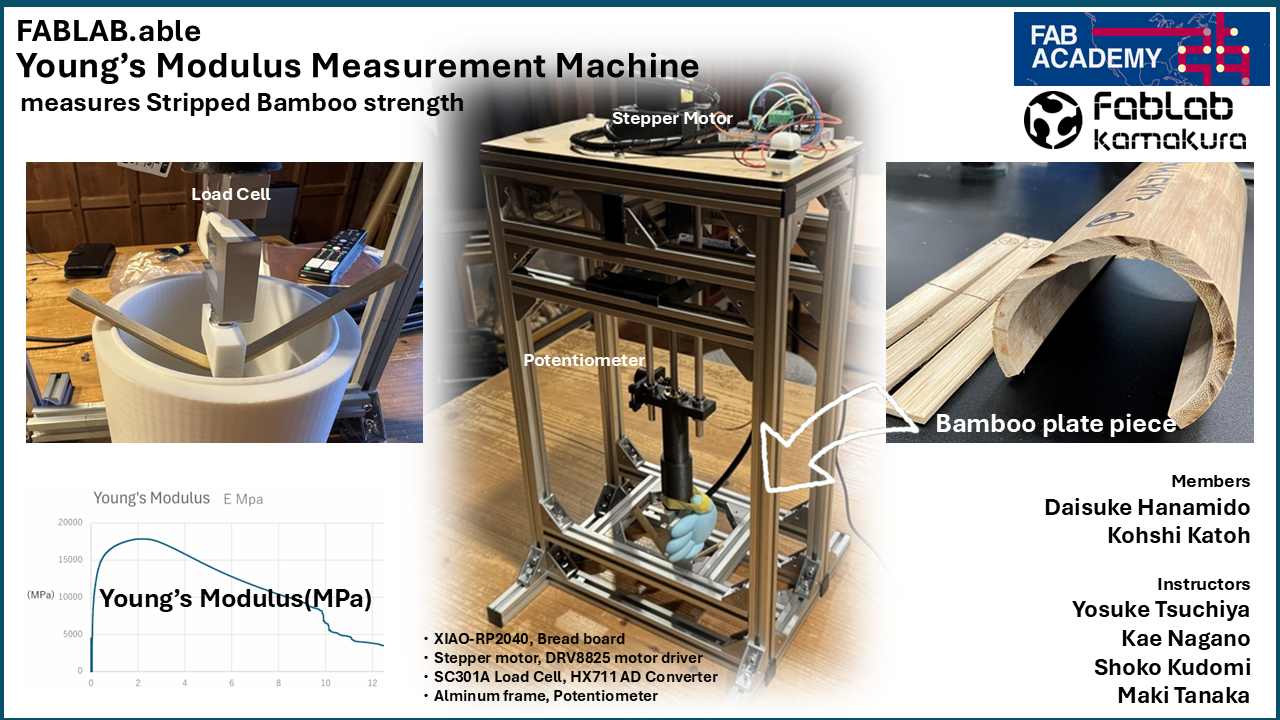
We decided to make simple but useful and FABLABable “Young’s Modulus Measurement Machine”.
Concept Designing
Here under is my initial sketch of Young’s Modulus Measurement Machine.
The concept of this machine is open source that everyone in FABLAB could remake with relevant accuracy.
Simplicity, low cost, with good accuracy (means enough rigidity) are the points that I focussed.
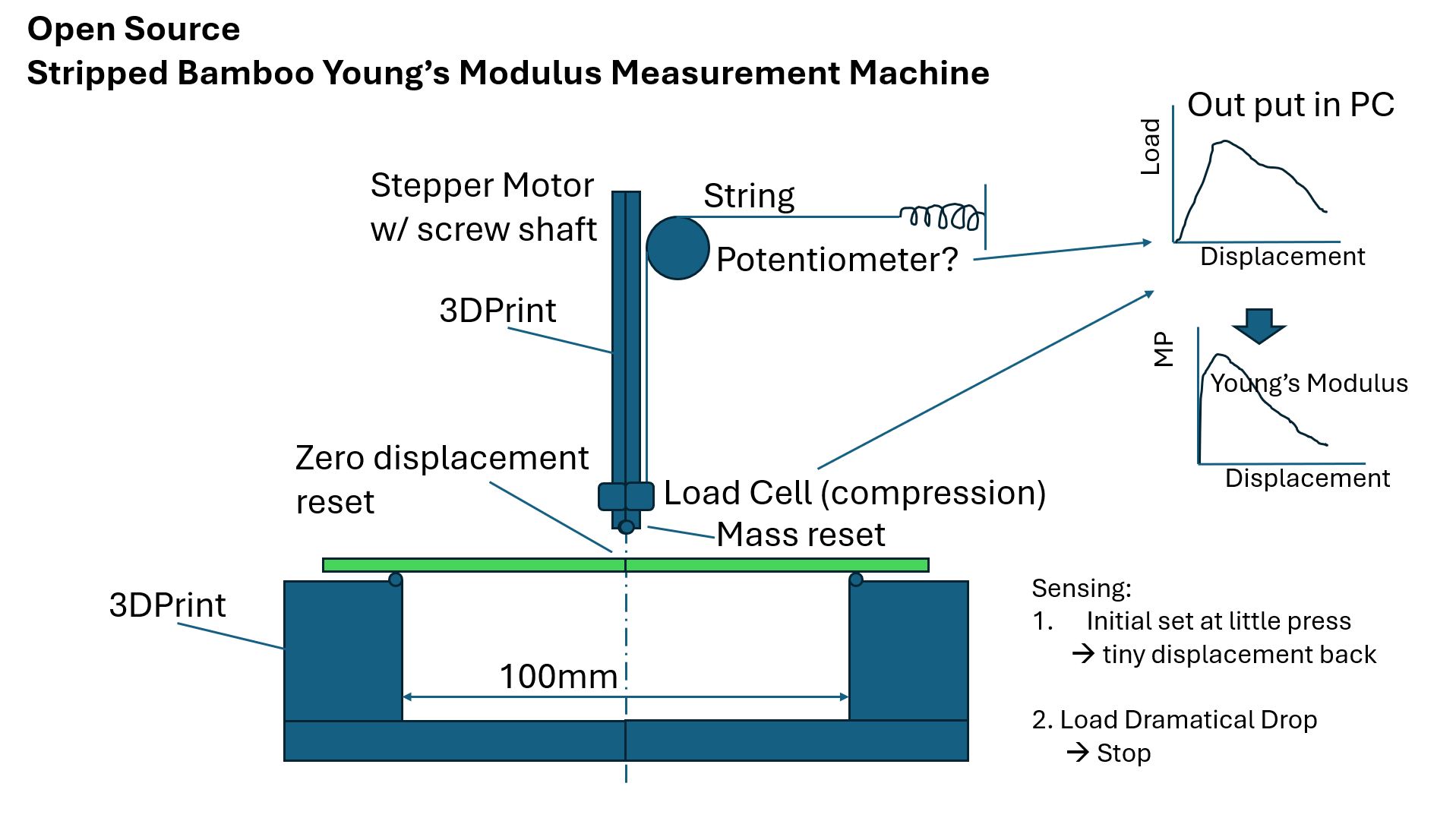
The machine consists of following parts;
-
Test piece base which can supports 150mm length of test piece with the support pillars distance as 100mm
-
3D printing Push Rod with tip at the edge and Load Cell installed in the middle as series to the tip
-
Potentiometer set at the main frame with the connection of a string attached to the fixation point at the frame via spring in series.
-
Push Rod connected to the Stepper Motor via Screw shaft and Coupling
-
Push Rod with the Load Cell moves down by the Stepper Motor’s rotation through Screw Shaft, and Measure the Load and Displacement by the Potentiometer pule as the angle.
How the system works:
-
The system should detect the first contact with load cell’s load signal, then stop and rise up a bit as the initial measurement position.
-
Then start measurement by Push Rod moving down until the Load Cell detects the Load level decreasing 10% of the peek load value, then stop.
-
The system will record the date of Load Cell, time, and potentiometer and save those data with CSV file format.
-
CSV file data will be calculated by Excel like PC application to get the Young’s Modulus Peek Value, and Graph is shown as the Young’s Modulus in vertical axis and Displacement as the horizontal axis.
Designing Push Rod with measurement feature
I started designing of Push Rod by referencing the [Onigiri Machine()]’s Push Rod which was designed by Shoko Kudomi.
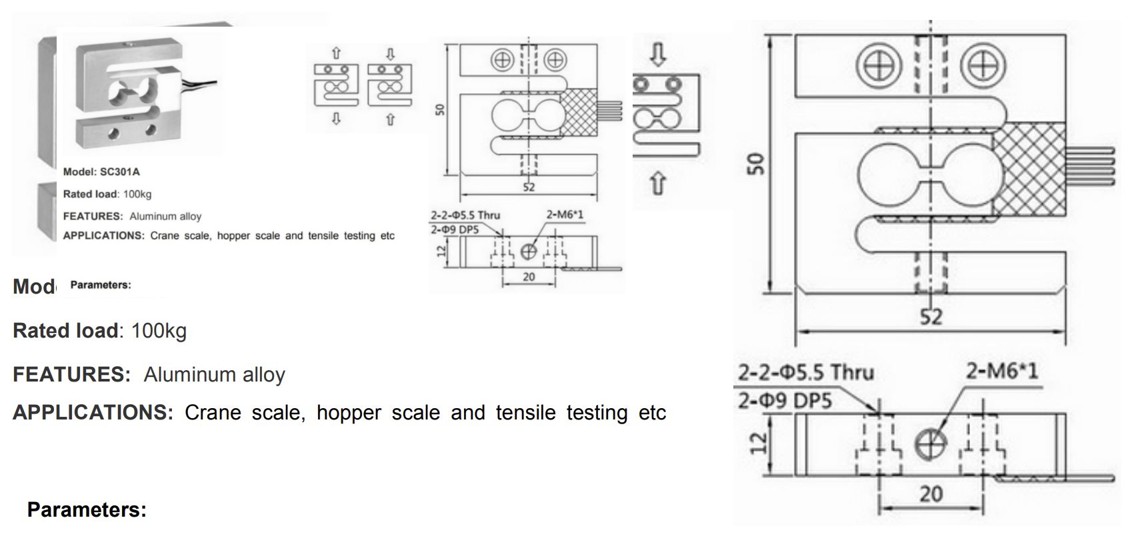
Selecting Load Cell and amplifier from following choice;
Designing Frame for Second Spiral
Designing Bearing fixation part
Designing Bearing Case by drawing Combined Bearing as
You can see the Young’s Modulus Measurement image and how it differs.
Young’s Modulus Comparison of Kenyan Bamboo
First Spiral
Considering the cost and range of measurement load, we decided to use Load Cell SC301A-100kg-V50 for the load measurement.
Here under is the Data Sheet of the Load Cell
To decide the length of Intermediate Rod, I drew a sketch to calculate the necessary length of the Intermediate Rod.
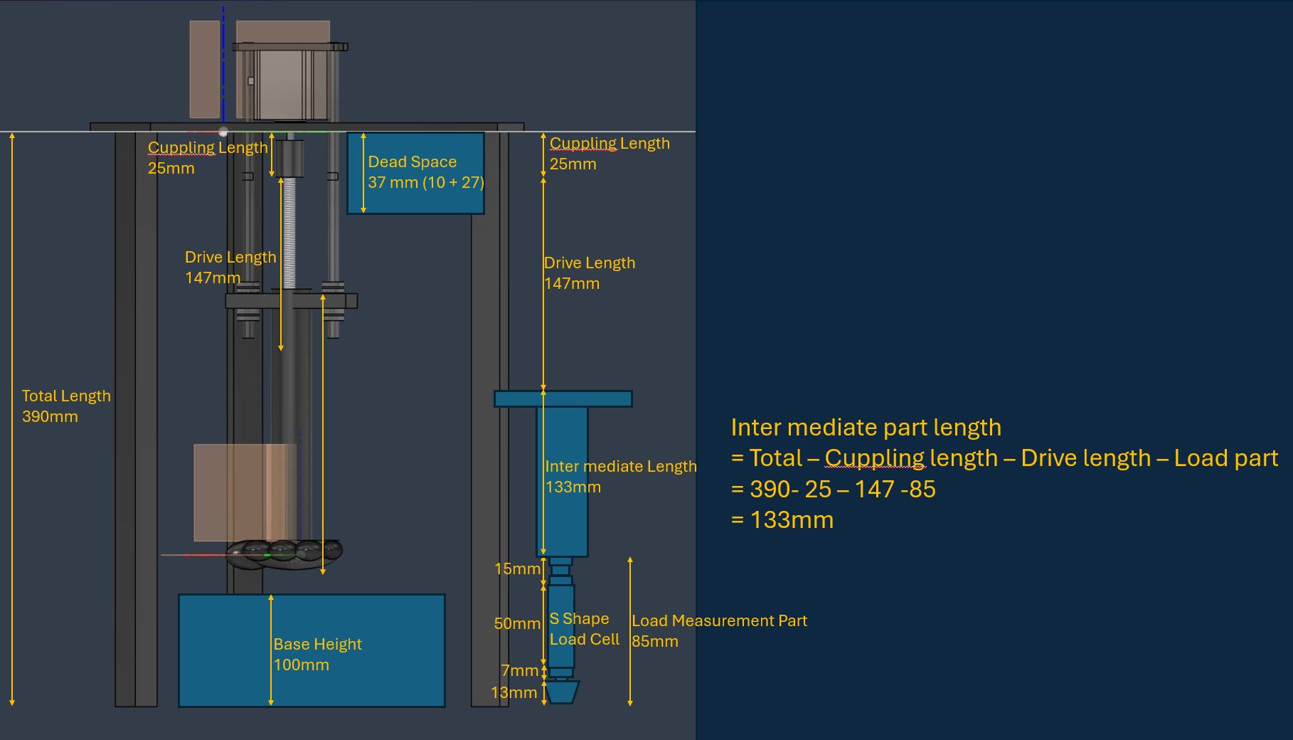
Intermediate Rod length
= Total - Coupling length - Drive length - Load part
= 390 -25 -147 -85 (mm)
=133mm
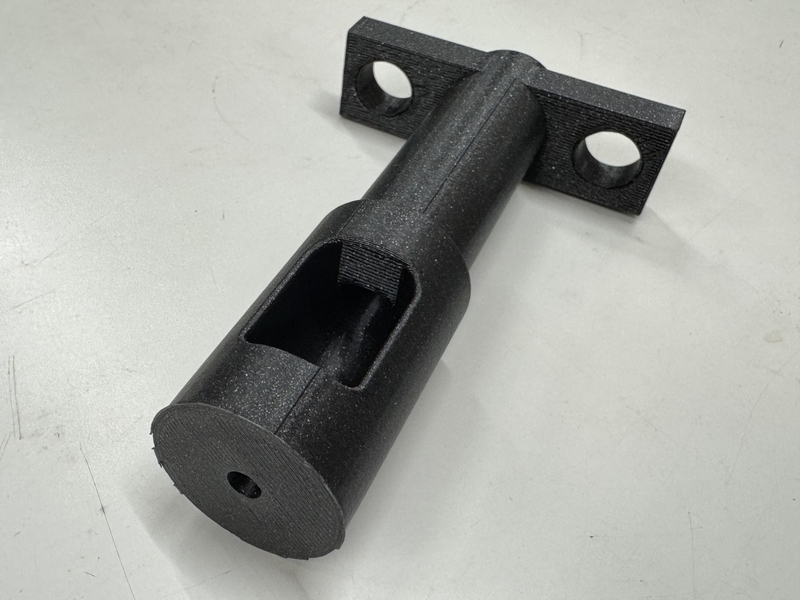
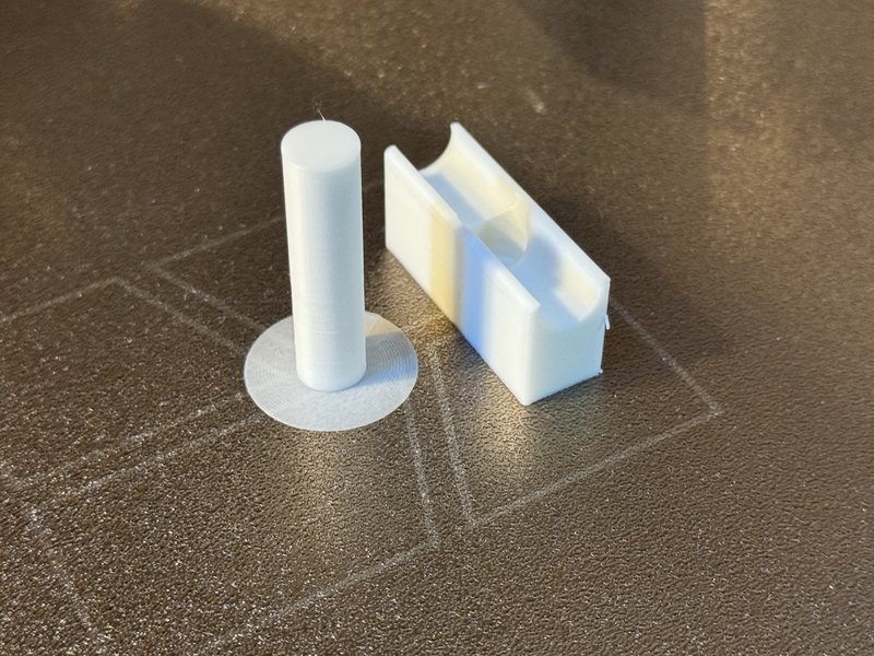
Here is the Tip to press the Bamboo Test Piece.

3D Printing Intermediate Shaft with different Support type.
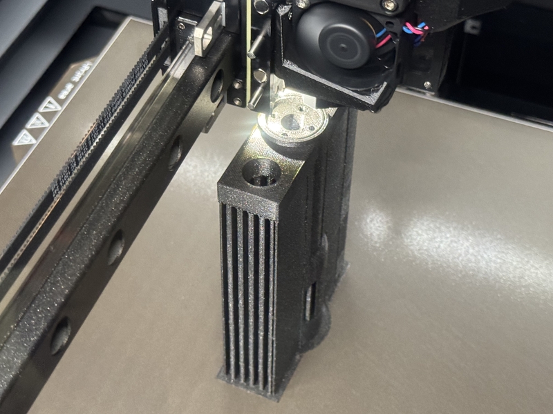
At this time, we made it possible to attach a load cell in between. This allows us to measure how much force is being applied.
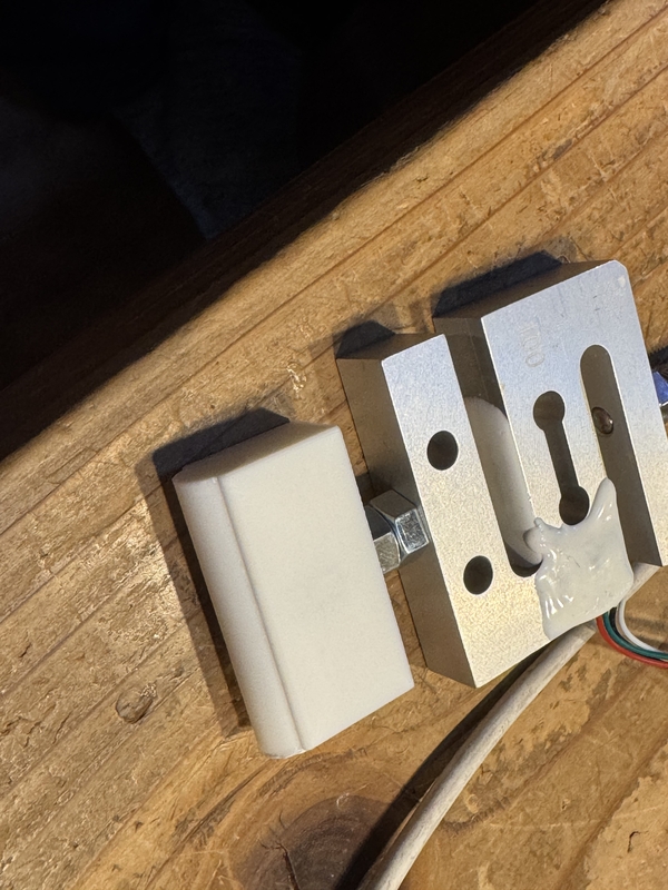
Load Cell SC301A-100kg-V50
3D printing Tip part
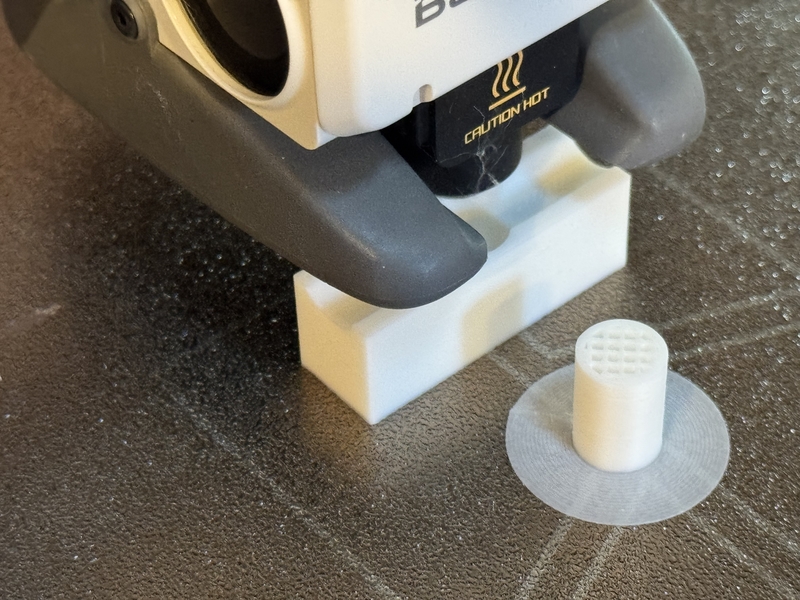
Connecting Tip and Load Cell
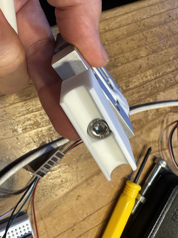
Pressing Tip is set under Load Cell.
After the first spiral test, we found that there is lack of stiffness and difficult to assure the accuracy with motor rotational axis data as the vertical displacement of the load cell due to the motor slipping at the reaction load at toughing the material.
Therefore, I decided to prepare for the potentiometer measurement method as an alternative idea of displacement measurement.
The reason of choosing potentiometer is the accuracy against cost seems reasonable in comparison with laser displacement measurement system if FABLAB Winam in Kenya need to purchase.
Second Spiral
Observing the motion of the motoring part, I found that the motor (from shaft to case) is holding the vertical load to press the Bamboo Test Piece which is not good condition.
Then he decided to modify the structure as following sketch.
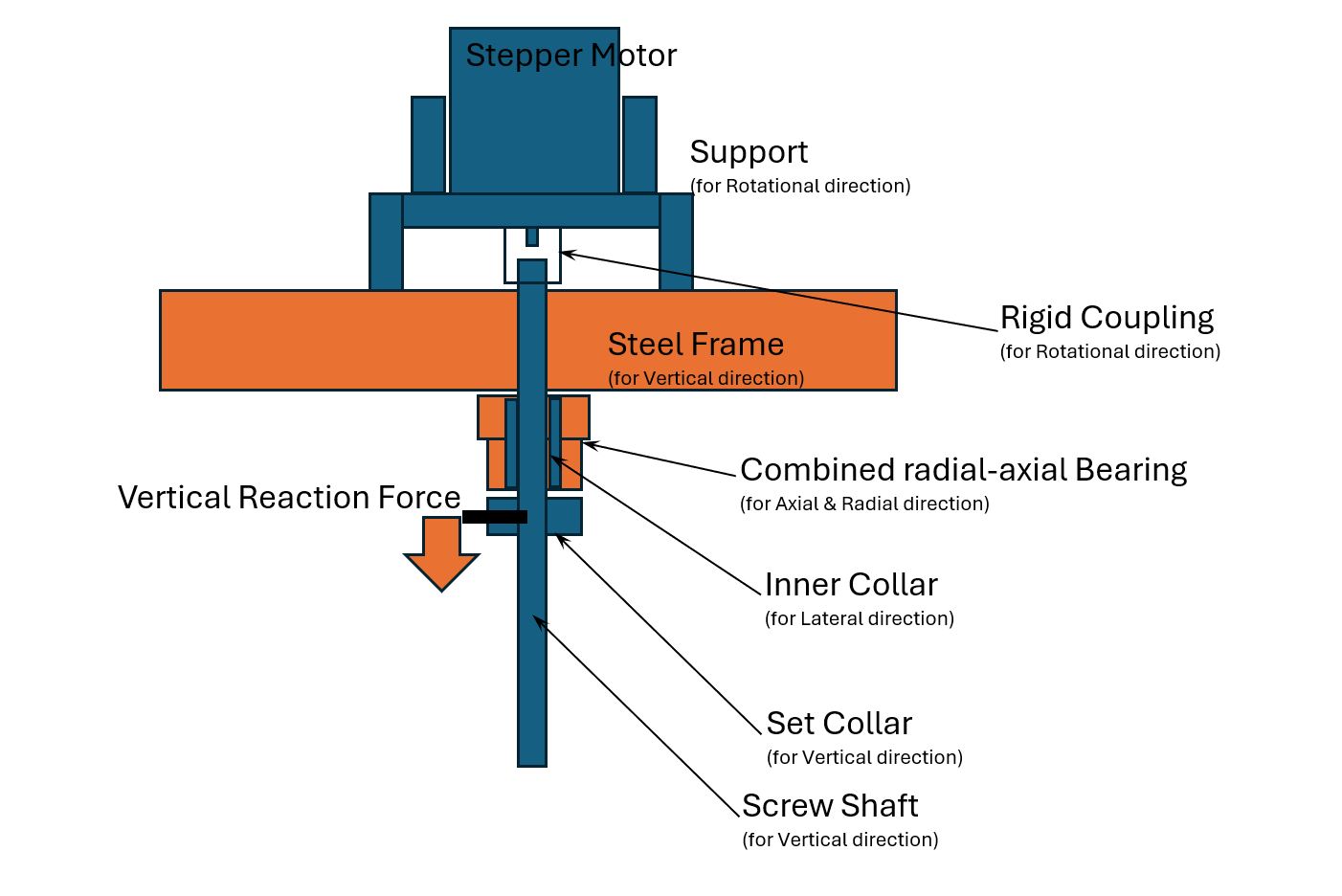
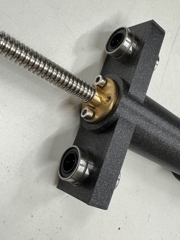
In above structure, the Vertical Reaction Force from Bamboo Test Piece is being hold by the Steal Frame through Combined Radial-Axial Bearing Not by the Stepper Motor Shaft.
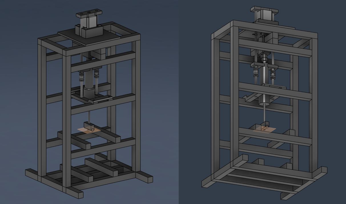
Detailed drawing process of New Frame for Second Spiral is written in Kohshi’s individual documentation.
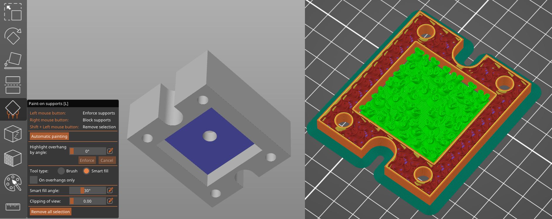
Second Spiral Frame Drawing
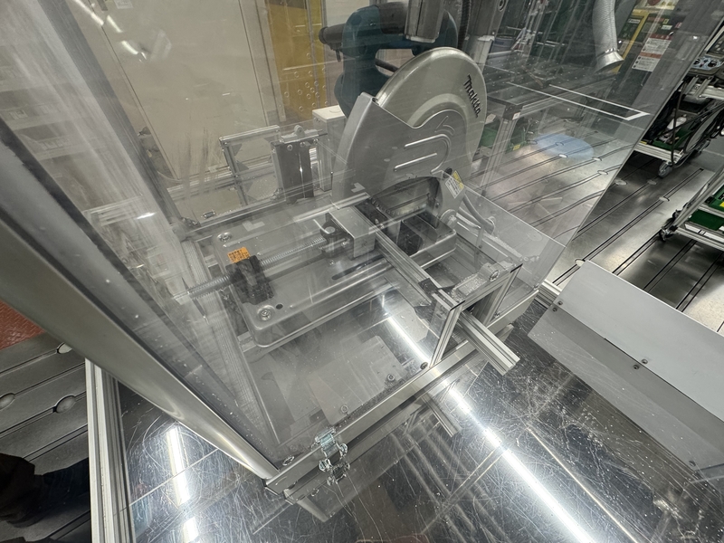
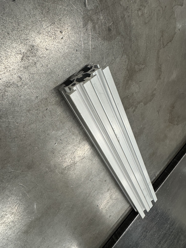
Setting Aluminum Frame in Cutting Machine
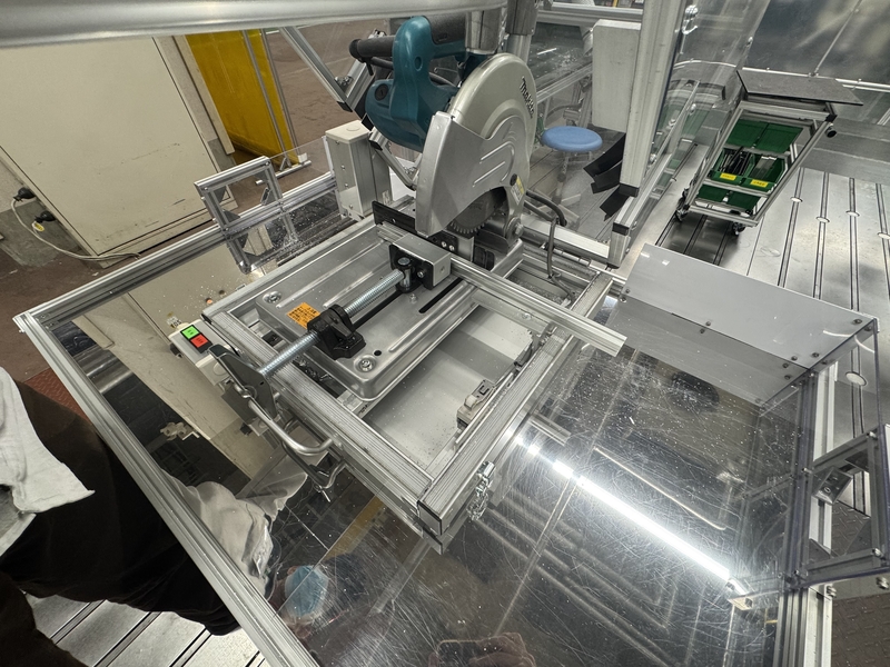
Cutting Aluminum Frame by covering the part
Cut Aluminum Frame
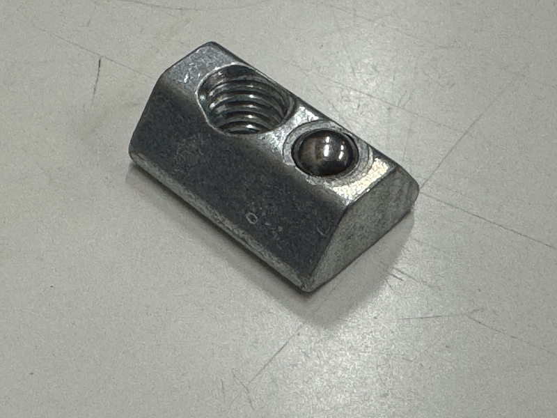
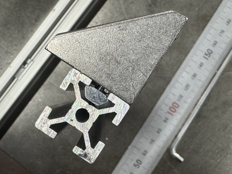
MISUMI Nut for Aluminum Frame
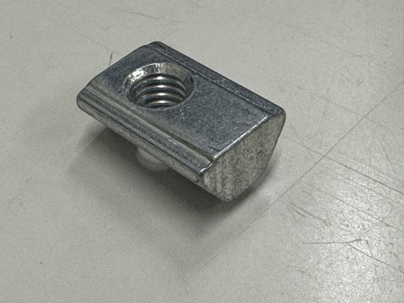
The nut has ball suspended by spring inside so that it makes assembly very easy without dropping the nut even at the vertical condition.
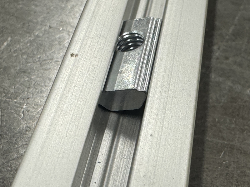
MISUMI Aluminum Frame nut can be installed in the middle of frame.
MISUMI Aluminum Frame cross section
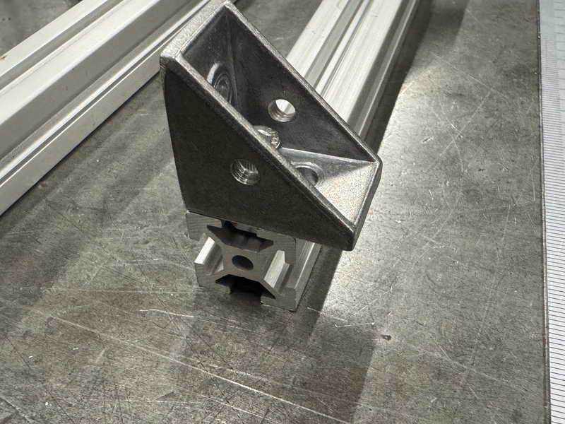
Assembling Frame by confirming the length of each part
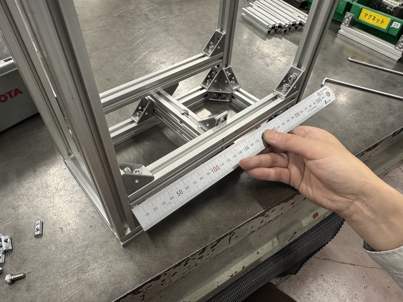
Base of frame was assemble on the flat table
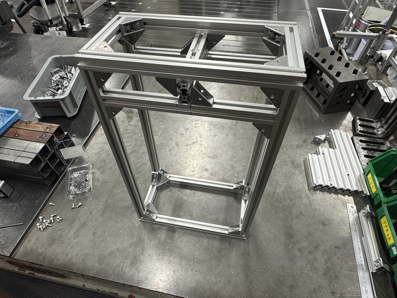
Main Frame was assembled
Designing Motor Case
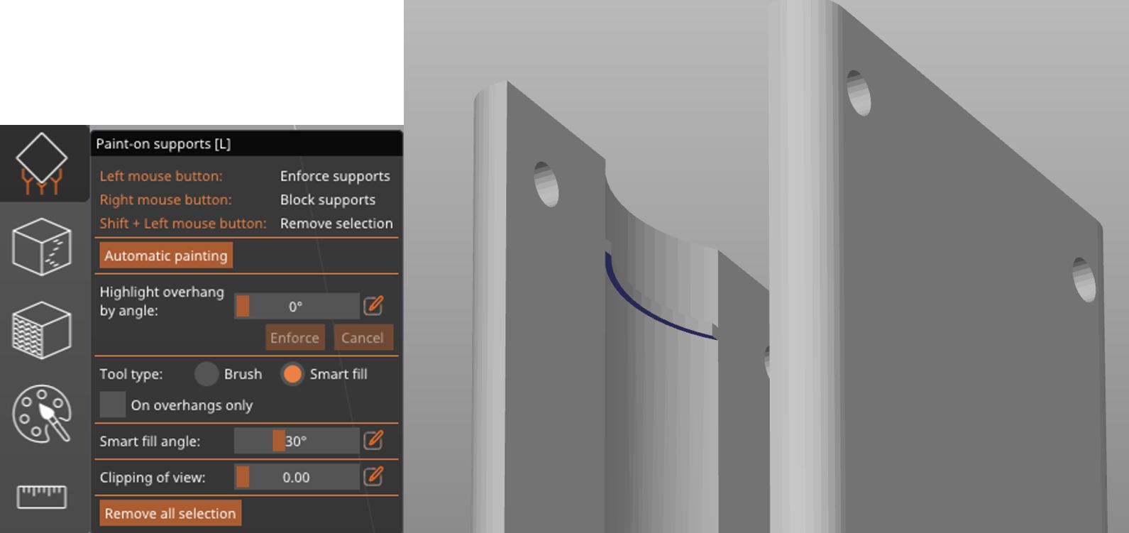
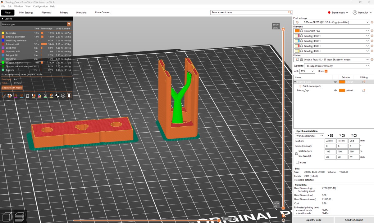
Motor Case 3DP was designed with manual support with support paint function in Prusa Slicer.
Motor Case 3DP setting for PrusaXL with PLA
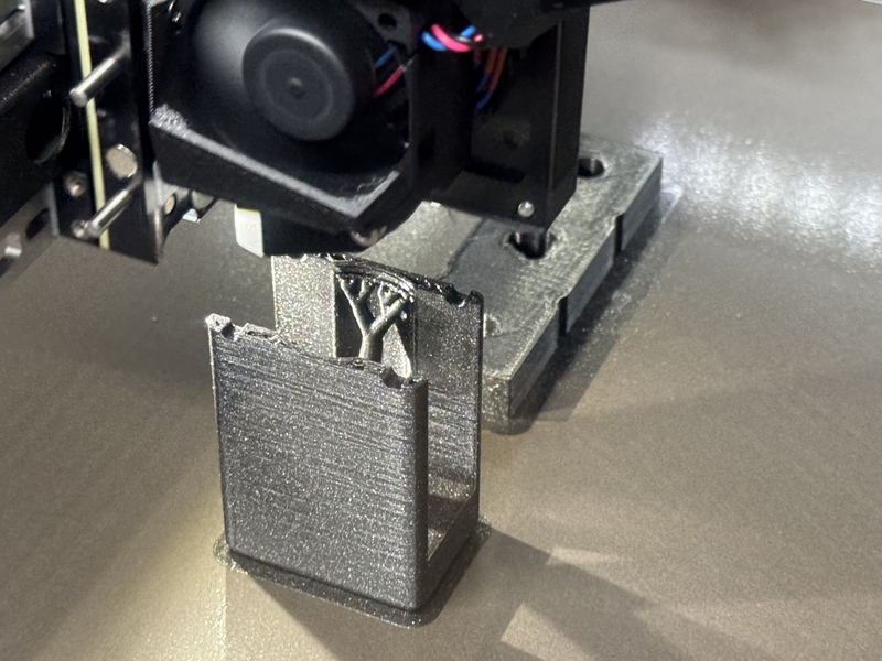
3D printed Motor Case
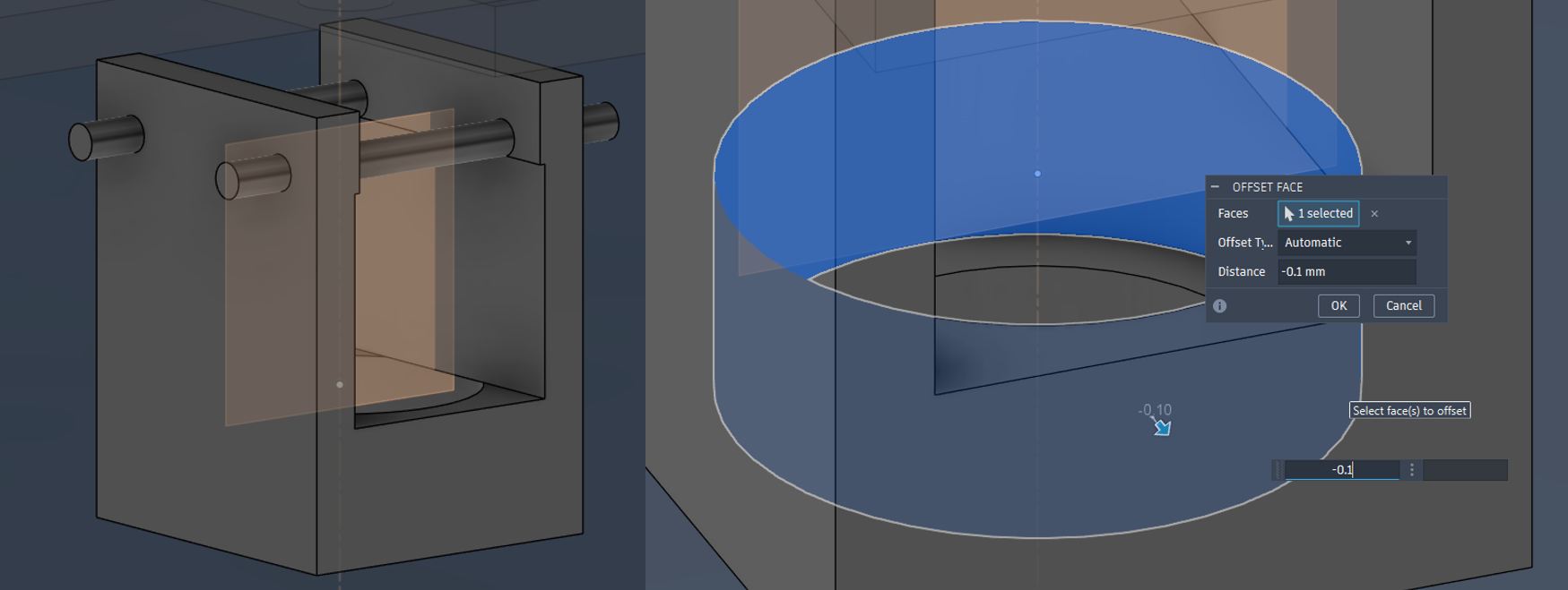
I decided to use Combined Bearing to bear the vertical reaction load at pressing the test piece by Aluminum Frame Not by the Stepper Motor shaft.
Combined Bearing NAX1023 was chosen with 2 of inner collars
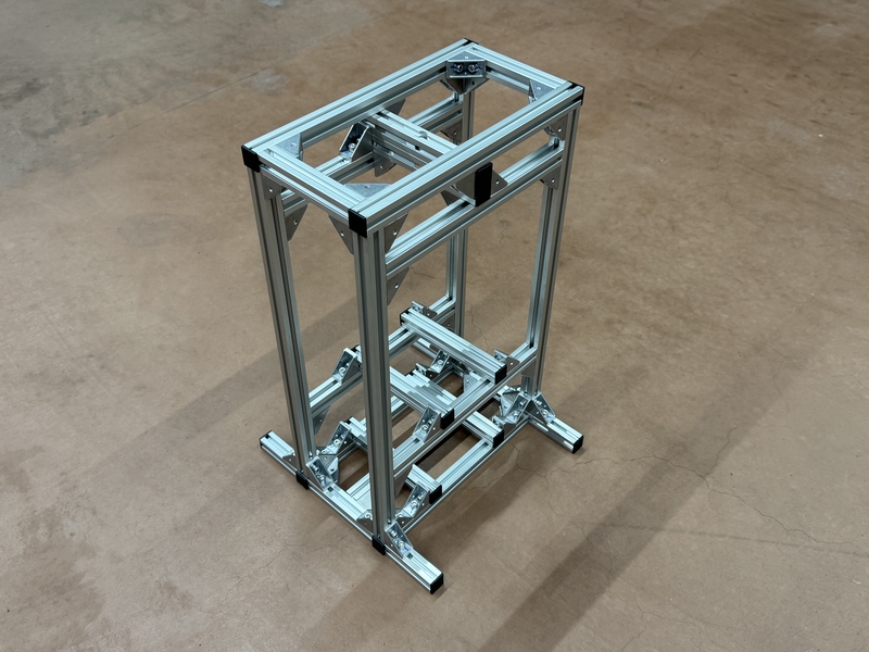
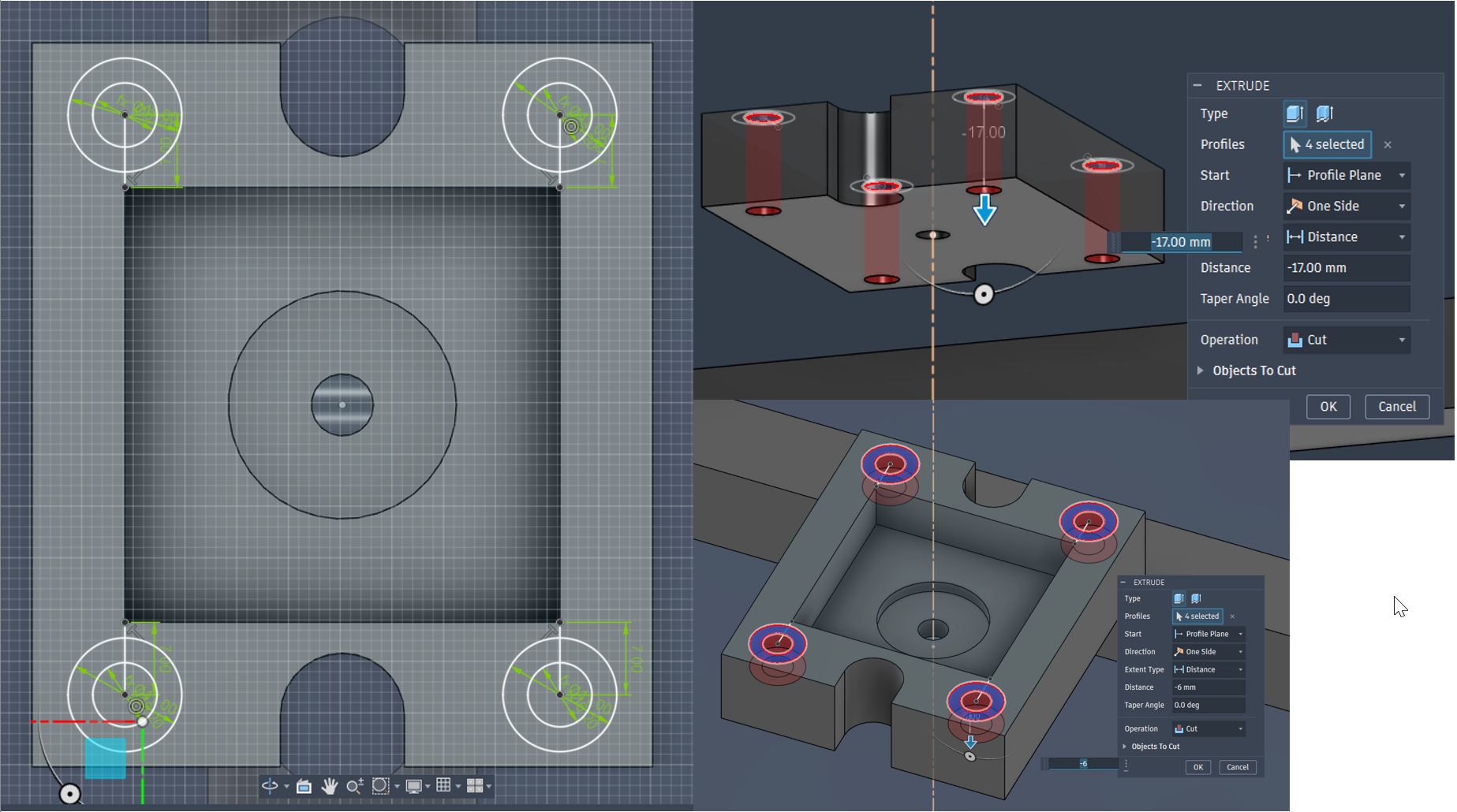
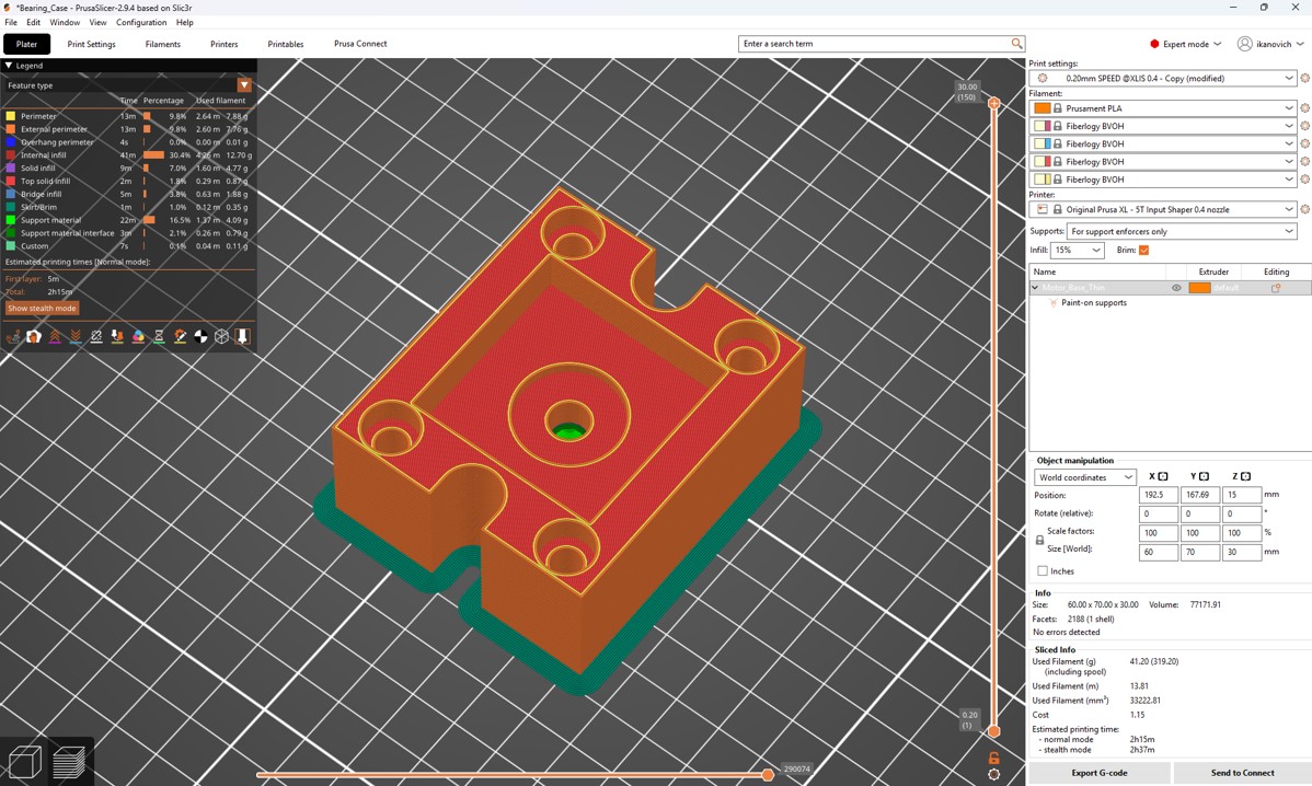
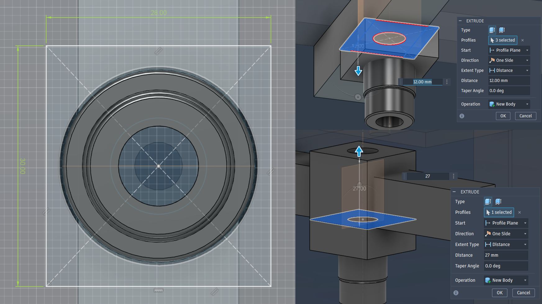
Designing Bearing Case
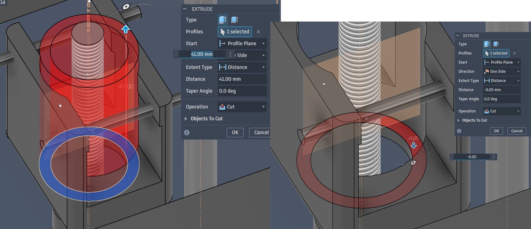
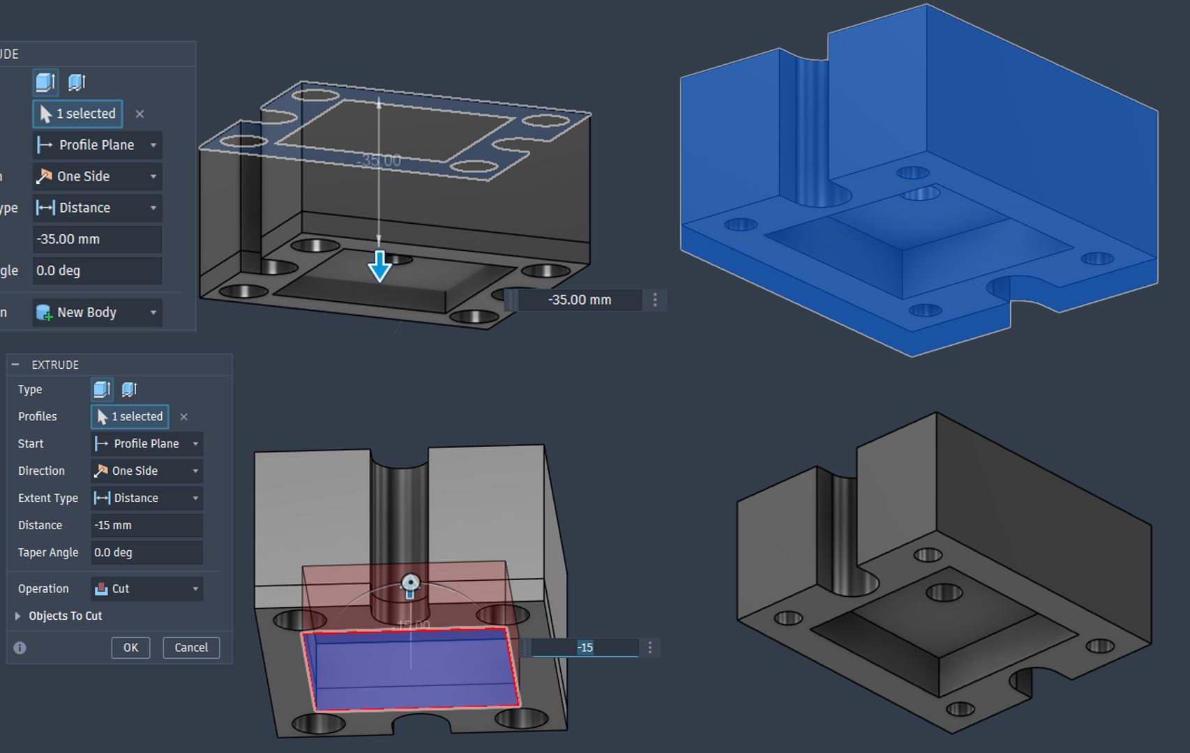
Bearing Case 3DP was designed with manual support with support paint function in Prusa Slicer.
Bearing Support 3DP setting for PrusaXL with PLA
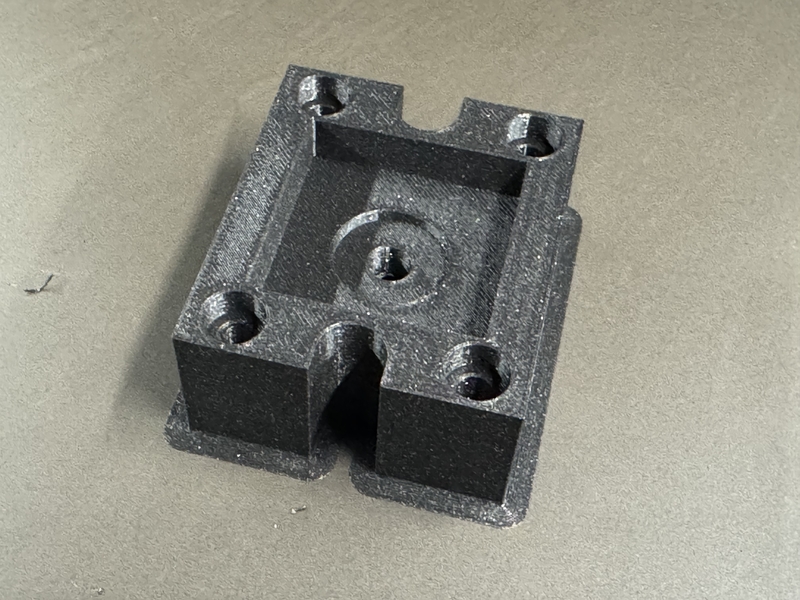
3D Printing Bearing Support part
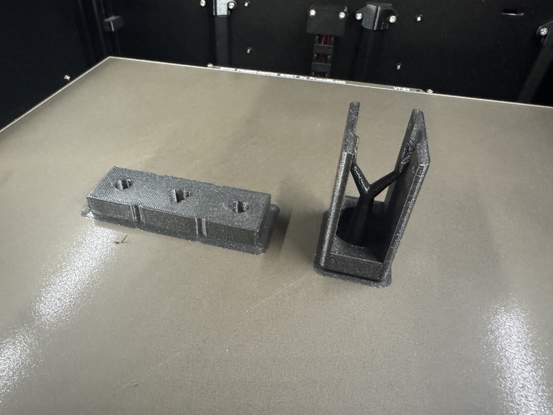
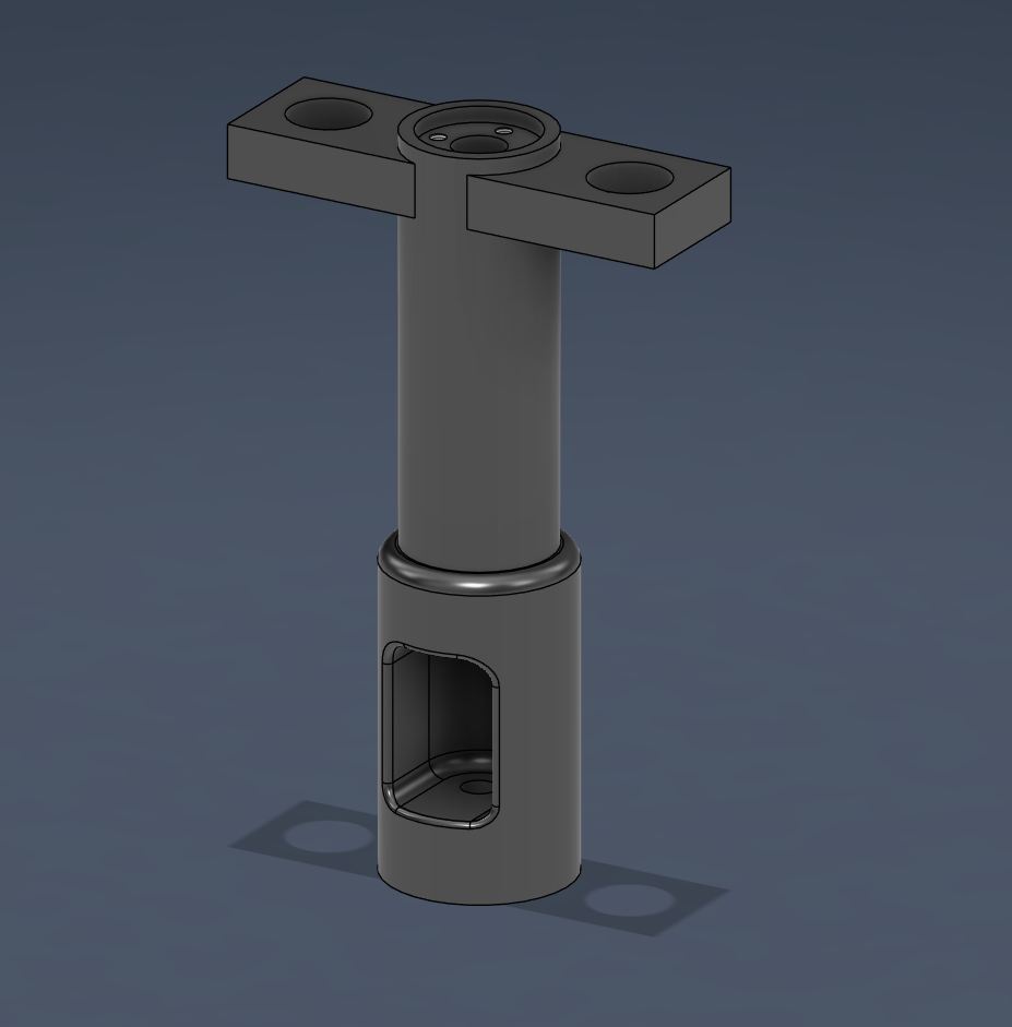
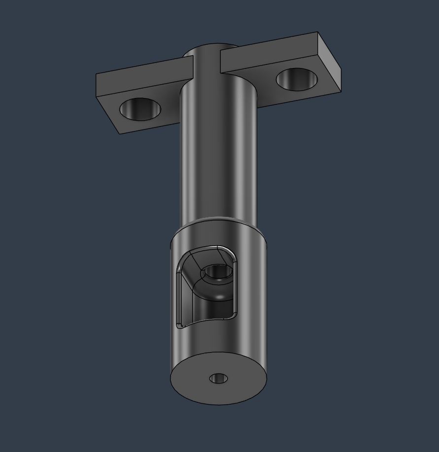
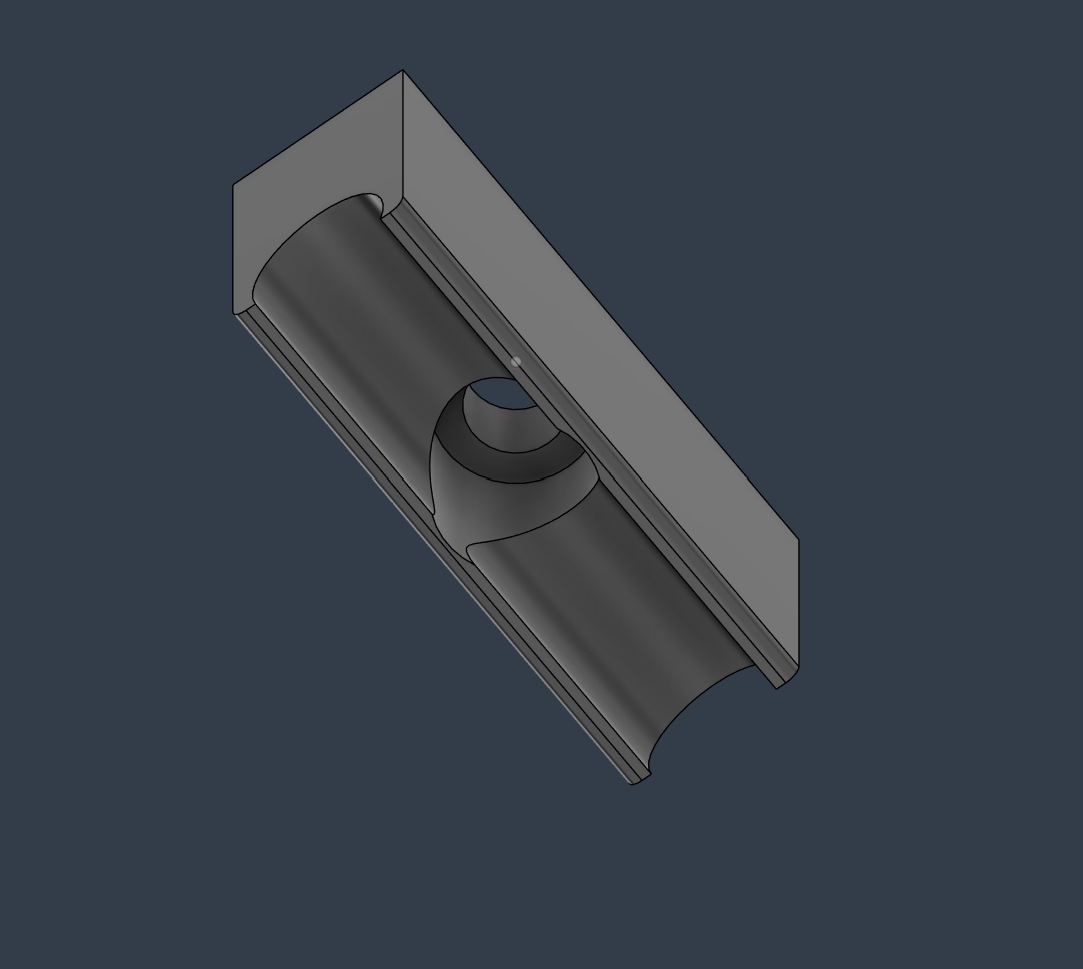
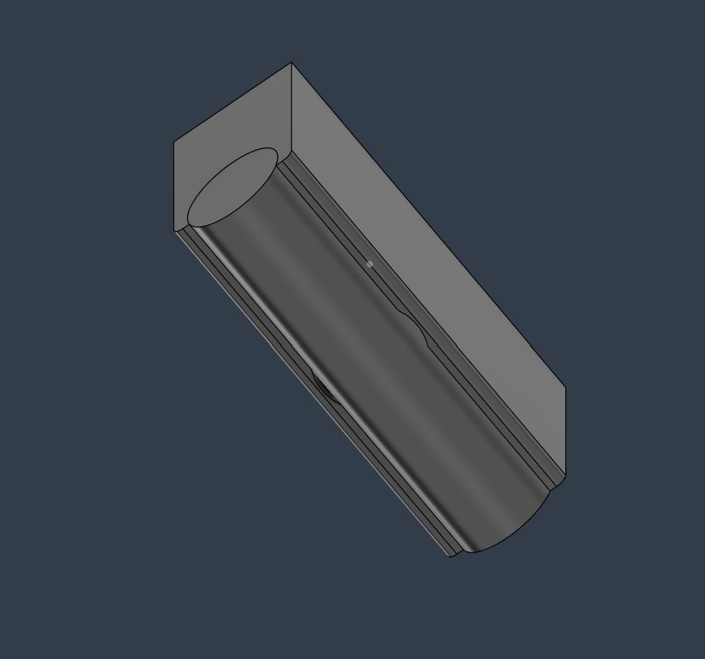
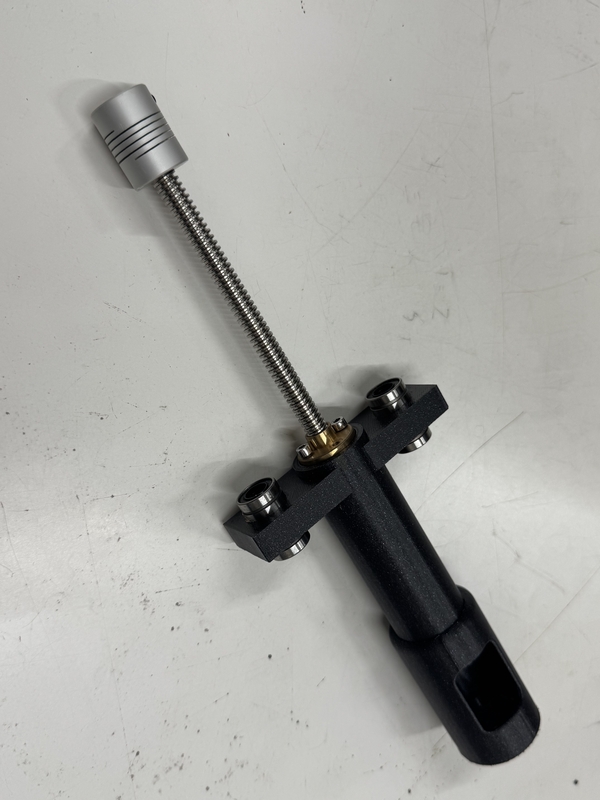
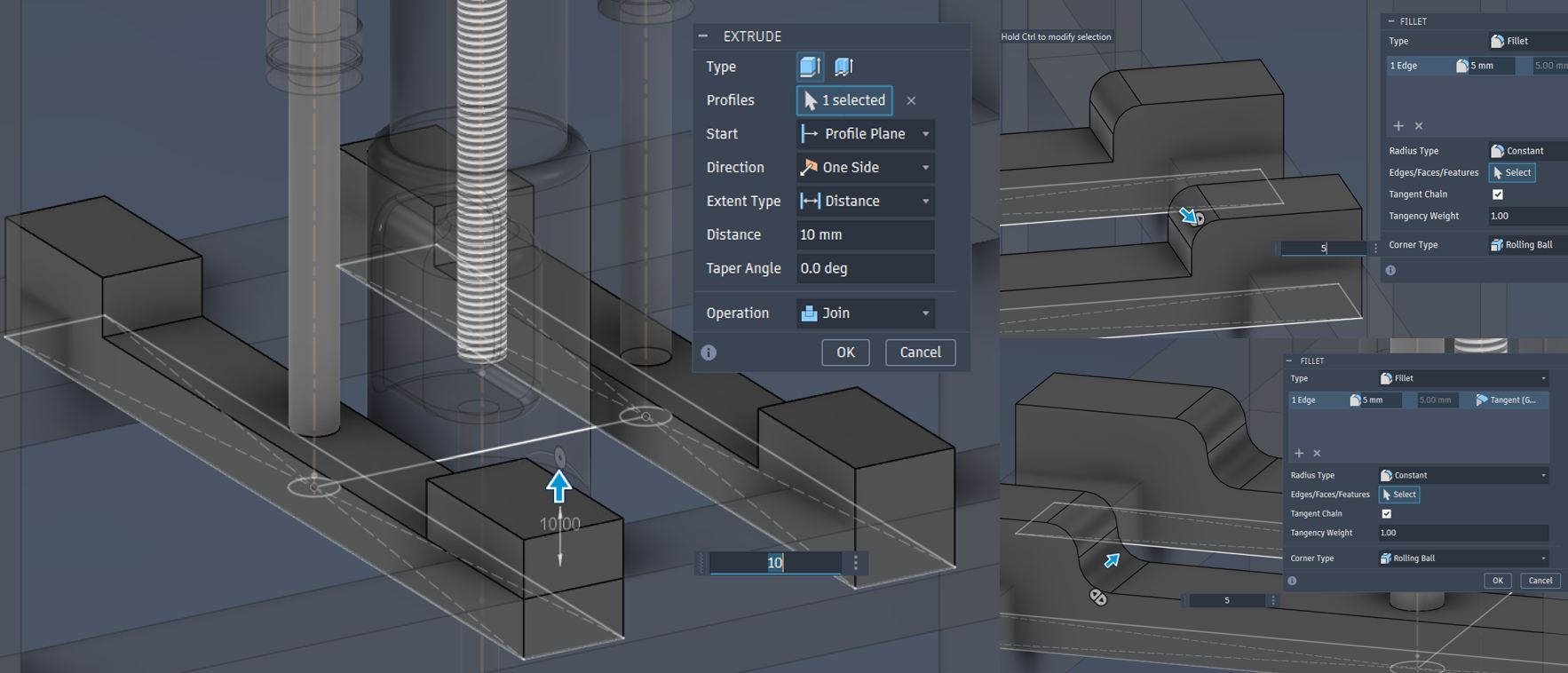
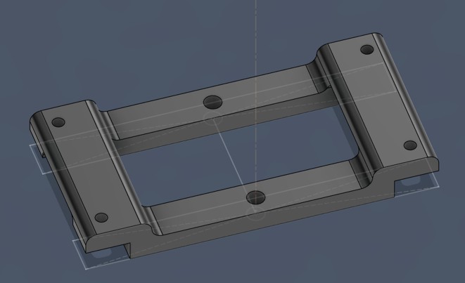
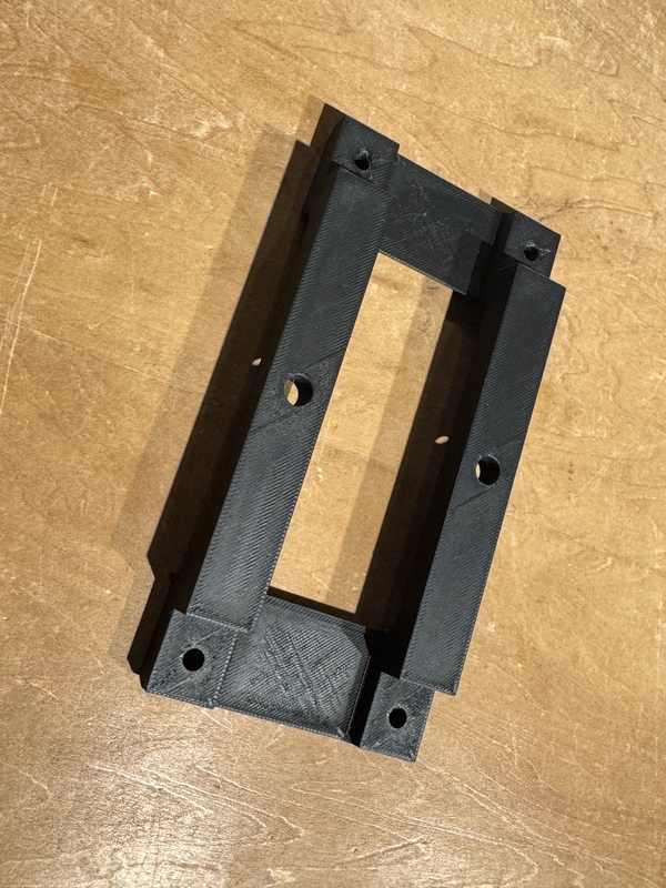
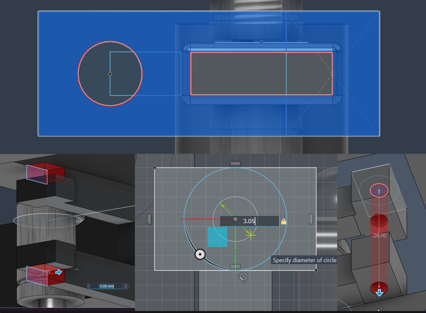
In order to stabilize the screw shaft especially for rotational angle direction, I designed rigid “Angle Stabilizer” for 3D printing.
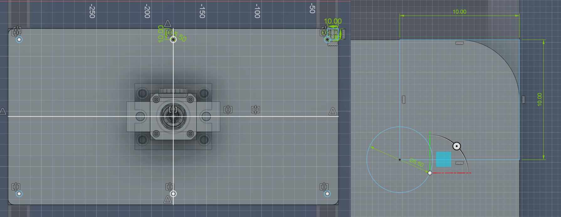
Designing Screw Shaft Angle Stabilizer
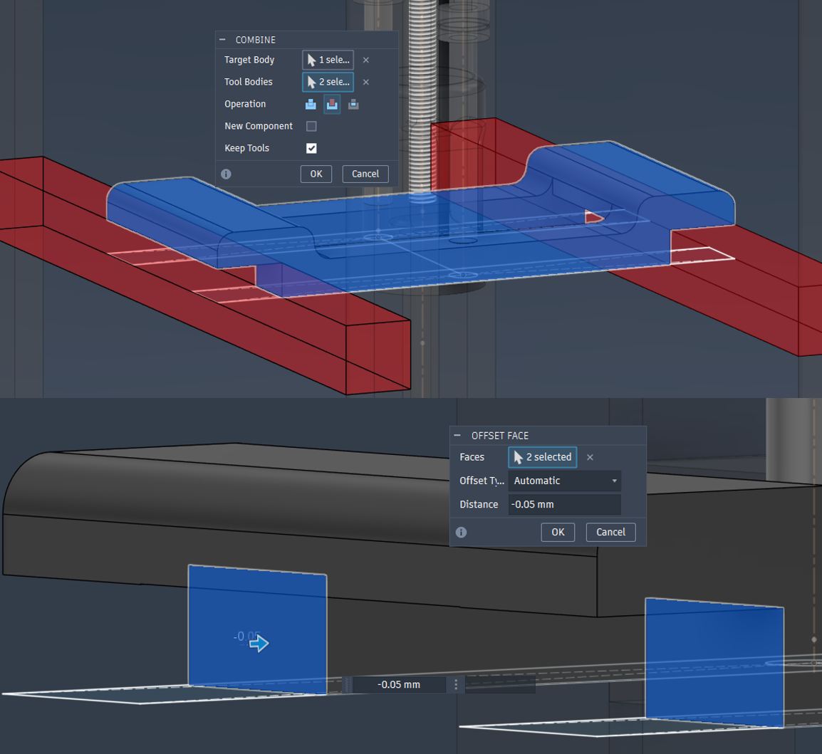
-0.05mm offset from the Main Frame contact point was done for assembly
φ5.5mm holes for M5 fixation
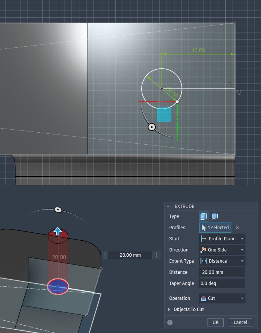
Angle Stabilizer design for 3D printing
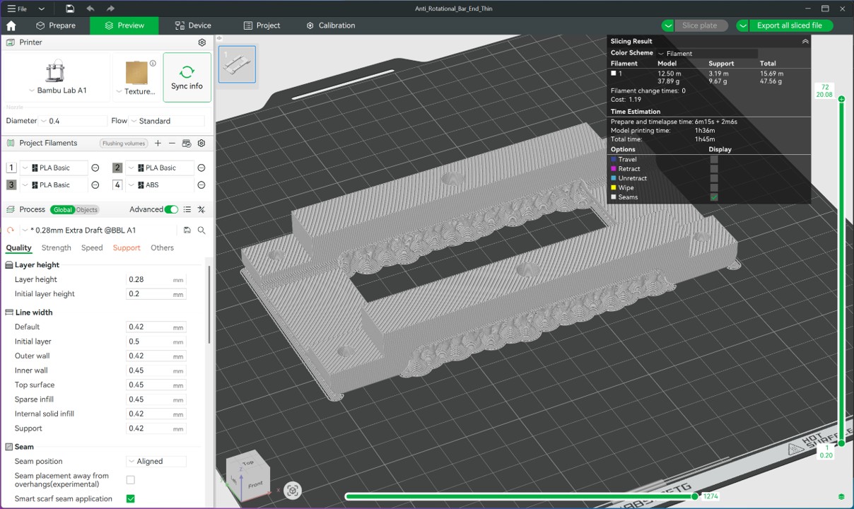
Angle Stabilizer 3DP was designed with manual support with support paint function in Bambu Studio.
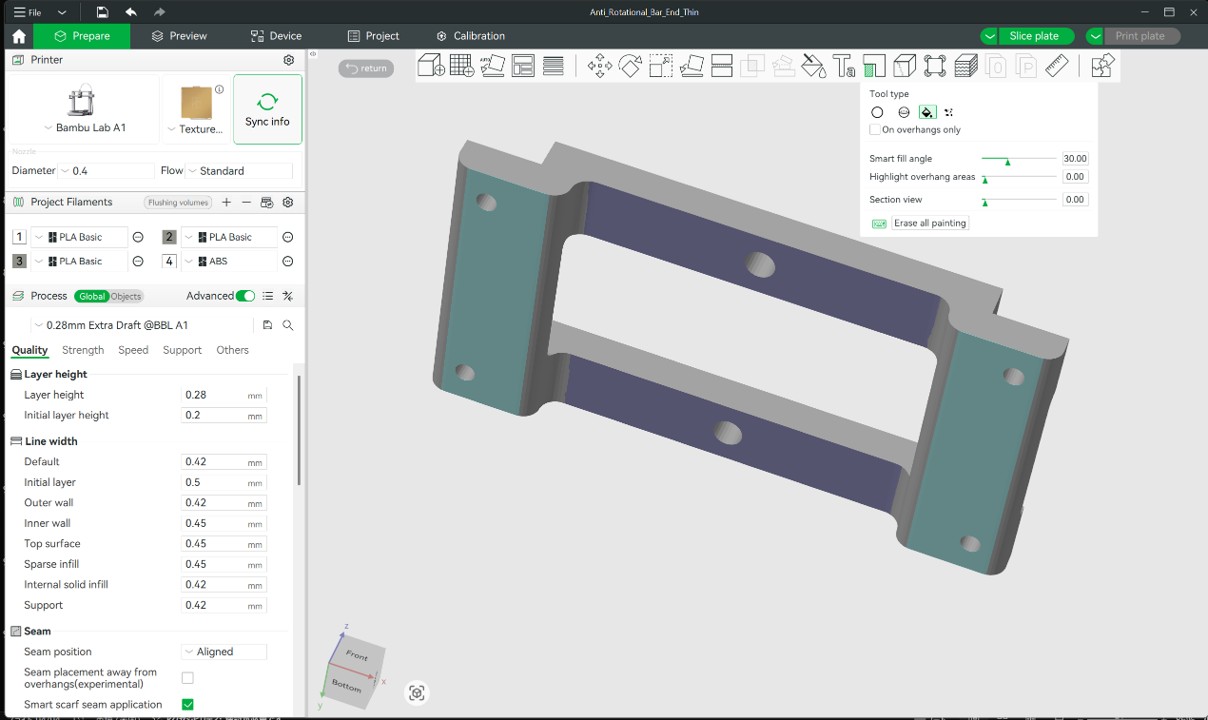
Angle Stabilizer 3DP setting for Bambu Lab A-1 with PLA
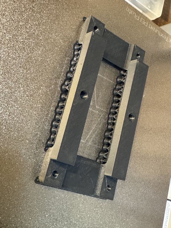
3D printed Push Rod Angle Stabilizer
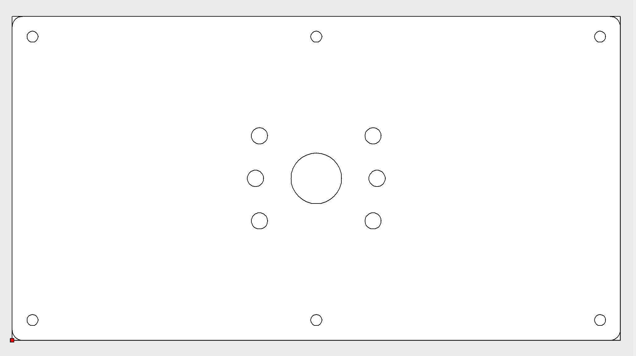
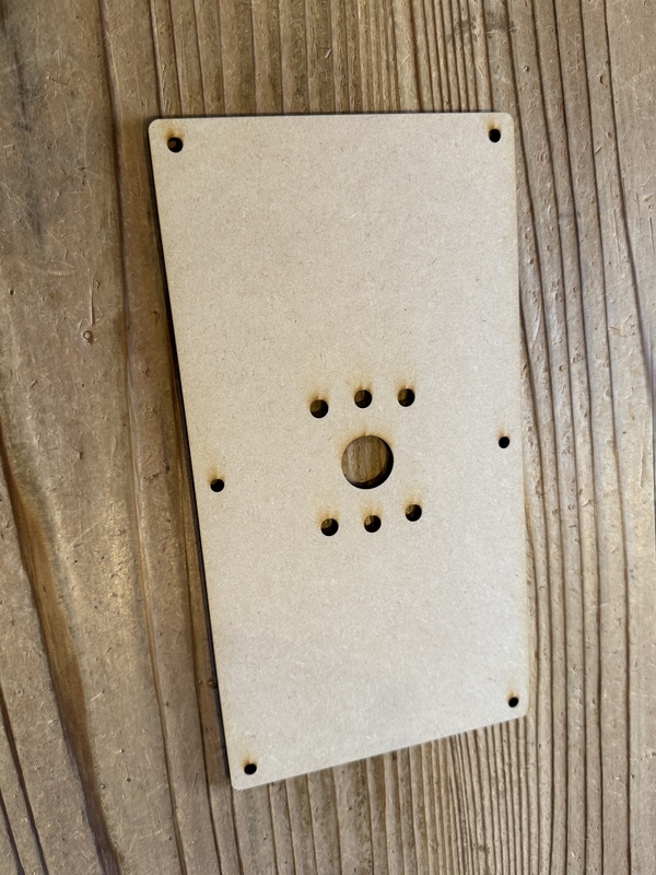
Designing Top Board for MDF Laser cutting
Export Top Board sketch as DXF file for Laser Cutting
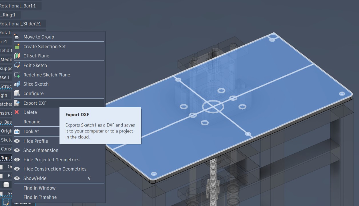
Top Board Design for Laser Cut
Illustrator file for Laser Cutting
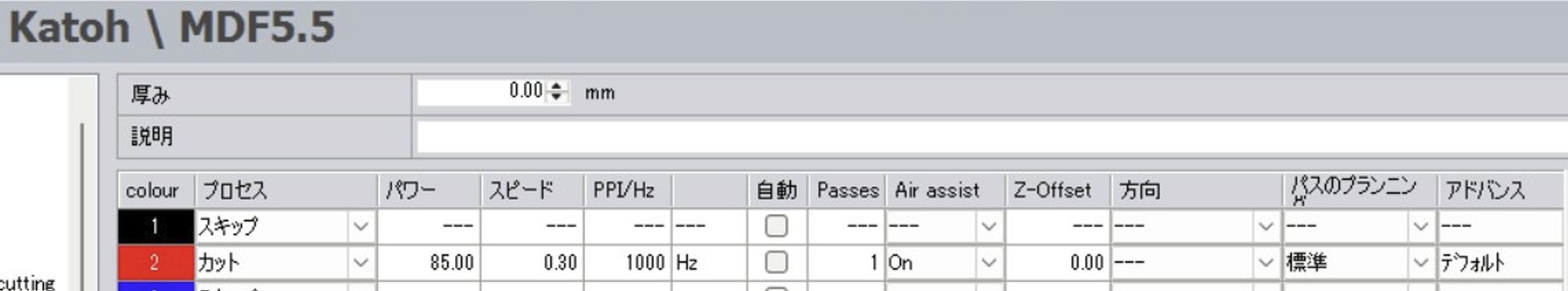
Testing for Laser cutting condition
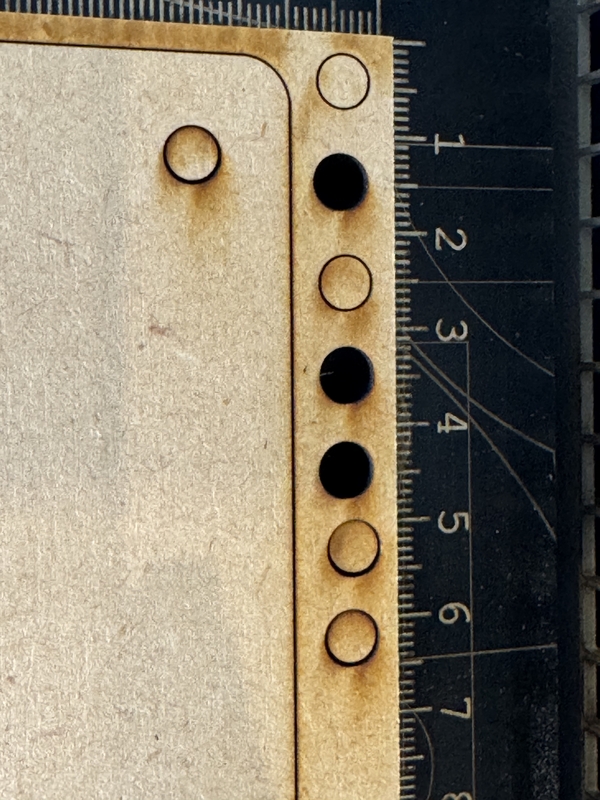
Laser Cut setting for 5.5mm MDF was chosen as following picture by Test Cut
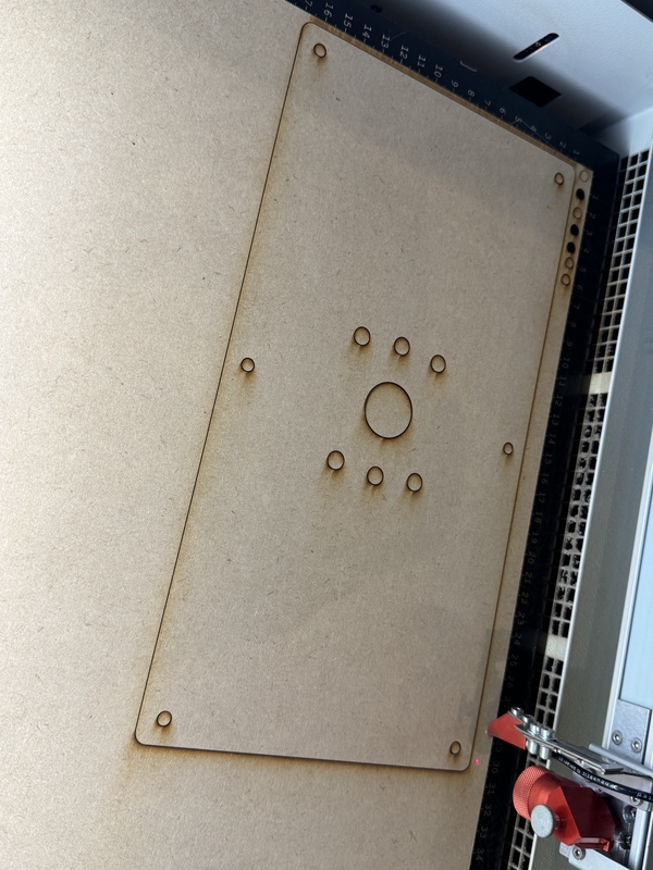
Preparation for the Laser Cutting
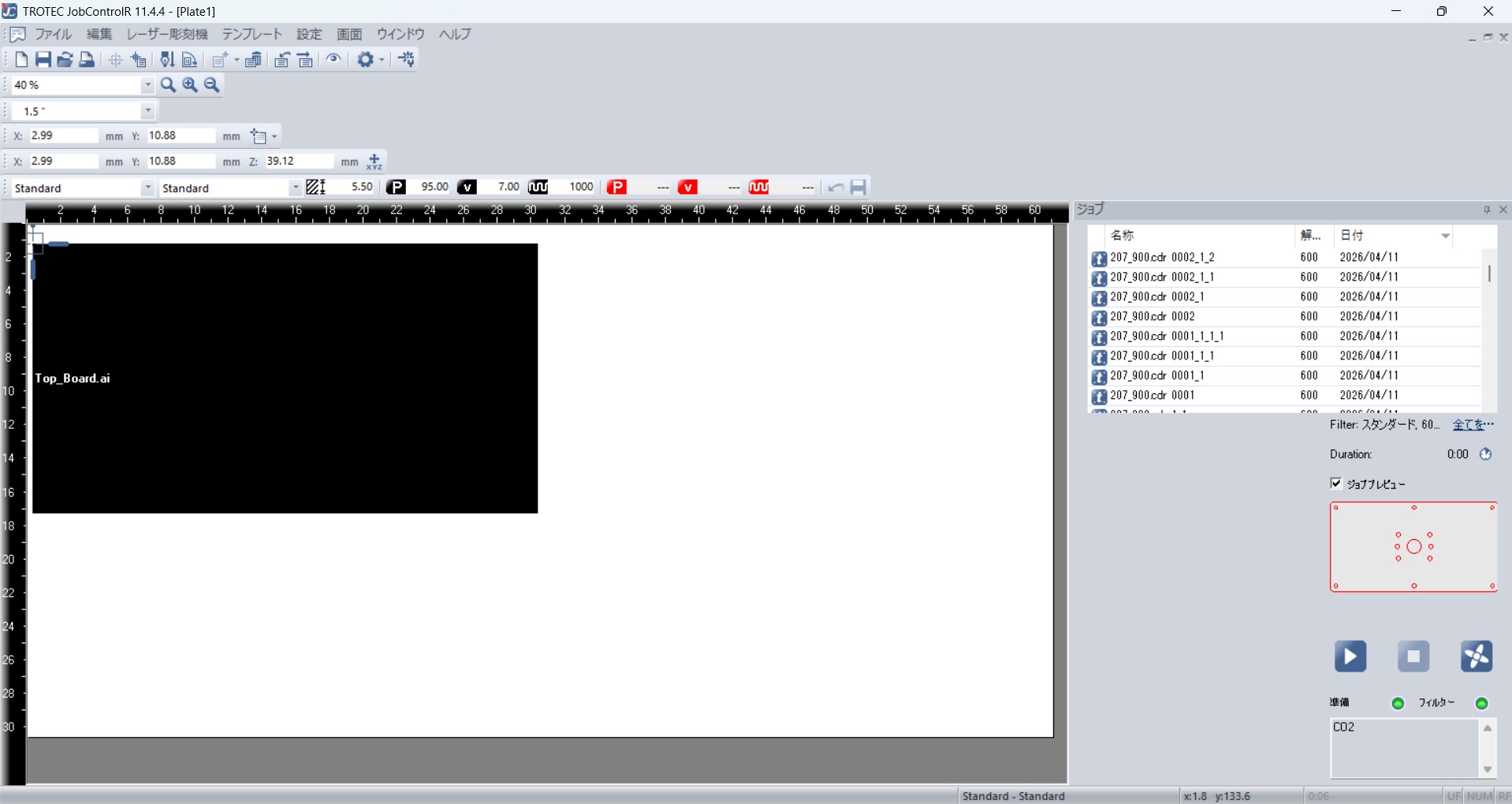
Laser Cut Top Board
2nd Spiral Test
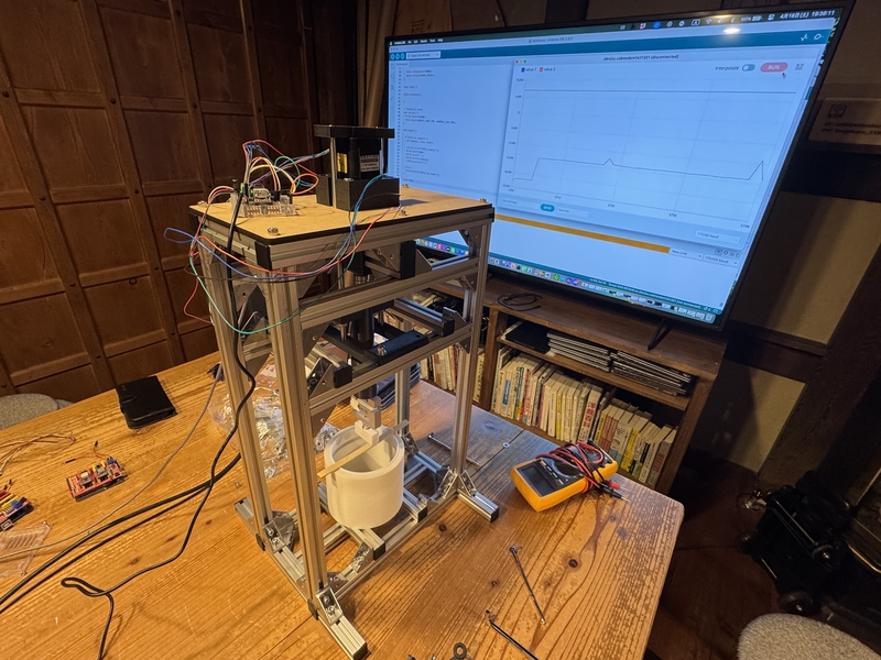
2nd Spiral test worked to some extent as the motor driven loading power with quicker motor rotation than our planning.
Displacement measurement by Potentiometer
Having difficulty to get displacement data from Stepper Motor Rotational Angle, we decided to install Potentiometer for displacement measurement.
I Started to design the Potentiometer Stay and system for the displacement measurement.
Designing potentiometer stay
Potentiometer Stay 3DP setting for Bambu Lab A-1 with PLA
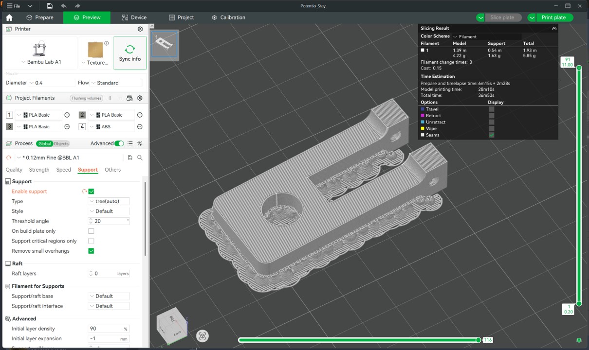
3D Printing Potentiometer Stay
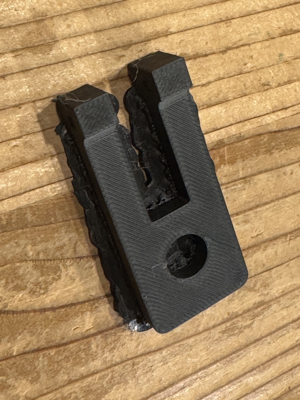
Potentiometer set at the Push Rod
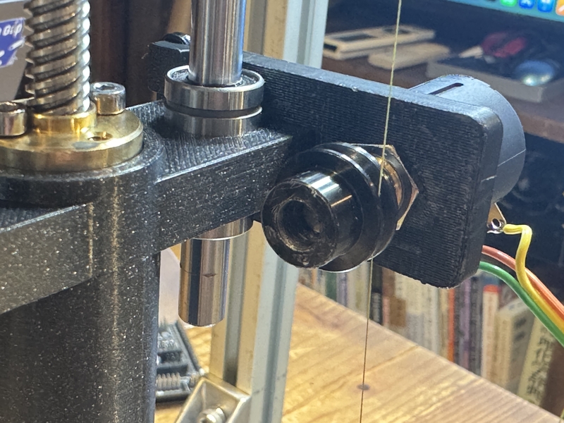
Potentiometer measurement system
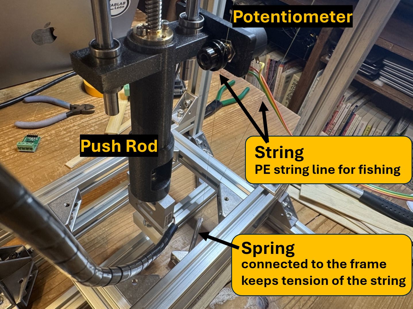
Potentiometer measures the travel distance of the Push Rod by the string which is fixed against the Main Frame via Spring.
The Spring keeps tension of the String so that there is no slip occurs at the spool of Potentiometer while it is rotating due to the travel.
PE Line (Izanas) for fishing is used as the string which has strong stiffness without deformation.
Panel making
Referencing last year’s Onigiri Machine Panel I made first version of Panel as follows;

Then I had instructions from Rico, Saheen, and Miriam that I should remove first two pictures regarding Kenyan bamboo site, since it is not directly explains the function of the machine but just back ground.
In order to make the explanation simple and straight away, place the machine photo in the middle with braking material photo and place the bamboo cross section photo in the right side for the balance.
Here under is the revised version of explanation panel.
Preparing for the presentation
Daisuke Hanamido made the video.
By following the flow of the video, I made following presentation sentences.
Team Kamakura developed
FABLAB.able Young's Modulus Measurement Machine
to measure the strength of Bio Material
such as Bamboo stripped plate.
At first, we utilized Last Year's
Onigiri Machine to confirm our concept.
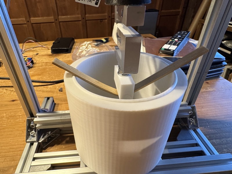
Place a test piece on the base,
Stepper Motor driven,
Tip with a Load Cell,
Displacement by Potentiometer
to measure the stiffness of material.
Found structural concern for accuracy.
We desided to design the frame structure with MISUMI Aluminum Frame.
We confirmed that this structure is feasible and
all the material we used are all easily reachable.
With a Laser Cutter and 3D Printer,
this machine is totally FABLAB.able.
This machine hopefully will support FABLAB Winam in Kenya
to develop next version of FABLAB.able Kinetic Seat
which might be presented in FAB26.
There are 81 bamboo species in Kenya.
It is known that the strength changes dramatically by heating, drying, keeping for a long time.
So, Measurement of Young's Modulus is very important to choose the right material and processing.
Here is the presentation of “Team Kamakura” at FAB Academy 2026 Machine week.
Presentation at FAB Academy 2026 Machine Week
Files
My designed files are in the –> Group Page Files